Advanced Sheet Metal Design Using NX Cad Challenge_7_ Metal bracket-II
Metal Bracket-II Design
Objective:
The main objective of this project is to design a sheet metal BRACKET II in NX cad sheet metal application workbench. Also, to perform the drafting for the bracket part.
Software used: NX 12.0
- To design and model the sheet metal Bracket II in NX by using some basic features.
- To learn to create sketches on defined planes as per requirement.
- To master the user interface and basic features of Sheet metal application in NX like Contour flange, Normal cutout, Break corner, Unbend, Creating holes, Re-bend, Advanced flange, Gusset and Flat pattern.
Introduction:
Sheet metal Design and Fabrication: -
# NX sheet metal design software includes material and process information in sheet metal-specific modelling features: bends, flanges, tabs, cutouts, beads, dimples, louvers, corner and edge treatments, patterns and other formable features. You can also quickly convert solid models to sheet metal components, and create sheet metal parts that enclose other components.
# With NX sheet metal CAD tools, you can apply standard values, such as material thicknesses and bend radii, based on industry or company best practices. With folding and unfolding capabilities, you can work with models at any stage of the fabrication process. NX sheet metal software creates accurate flat patterns for documentation and manufacturing.
Design Methodology:
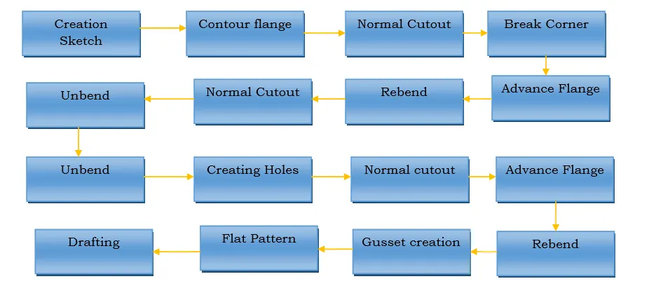
Description:
The sheet metal Bracket II has been done with the above flow chart process. While designing the default thickness, bend radius relief depth and relief width value are set to 1mm at the Menu → Preferences → Sheet Metal here you can change the Sheet Metal thickness whenever necessary.
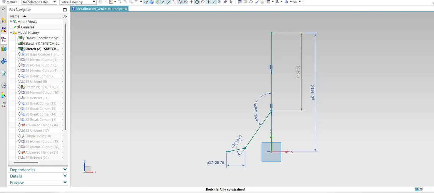
The sketch is drawn in the YZ plane and the Contour flange command is used for creating the base of the part.
Explanation and Procedure:
1.Direct Sketch:
We use its tools to create a base sketch. (For eg: Rectangle, Circle, Line, etc.)
Sketch creation:
Sketch in the YZ Plane.
In order to create a couple of normal cut-outs in the bracket, the sketch is initially created keeping the profile accurately.
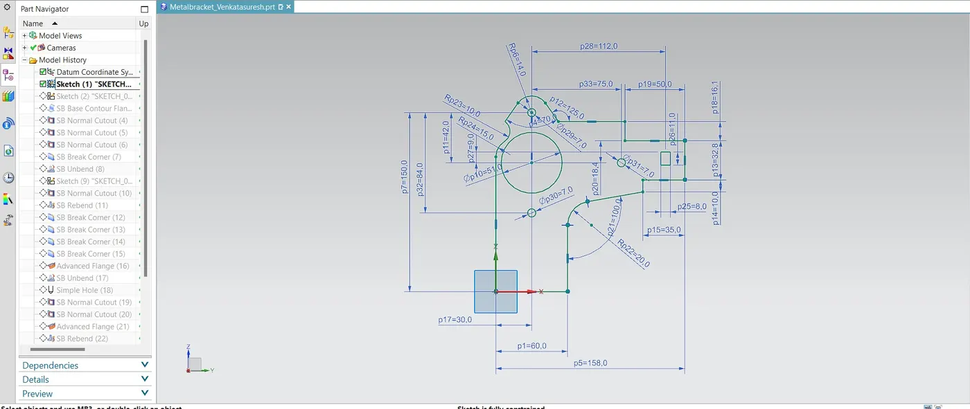
Sketch for contour flange:(XZ Plane)
A contour flange can be created from any open curve. For this bracket, the sketch is created in an XZ plane with the following dimensions.
2.Contour flange:
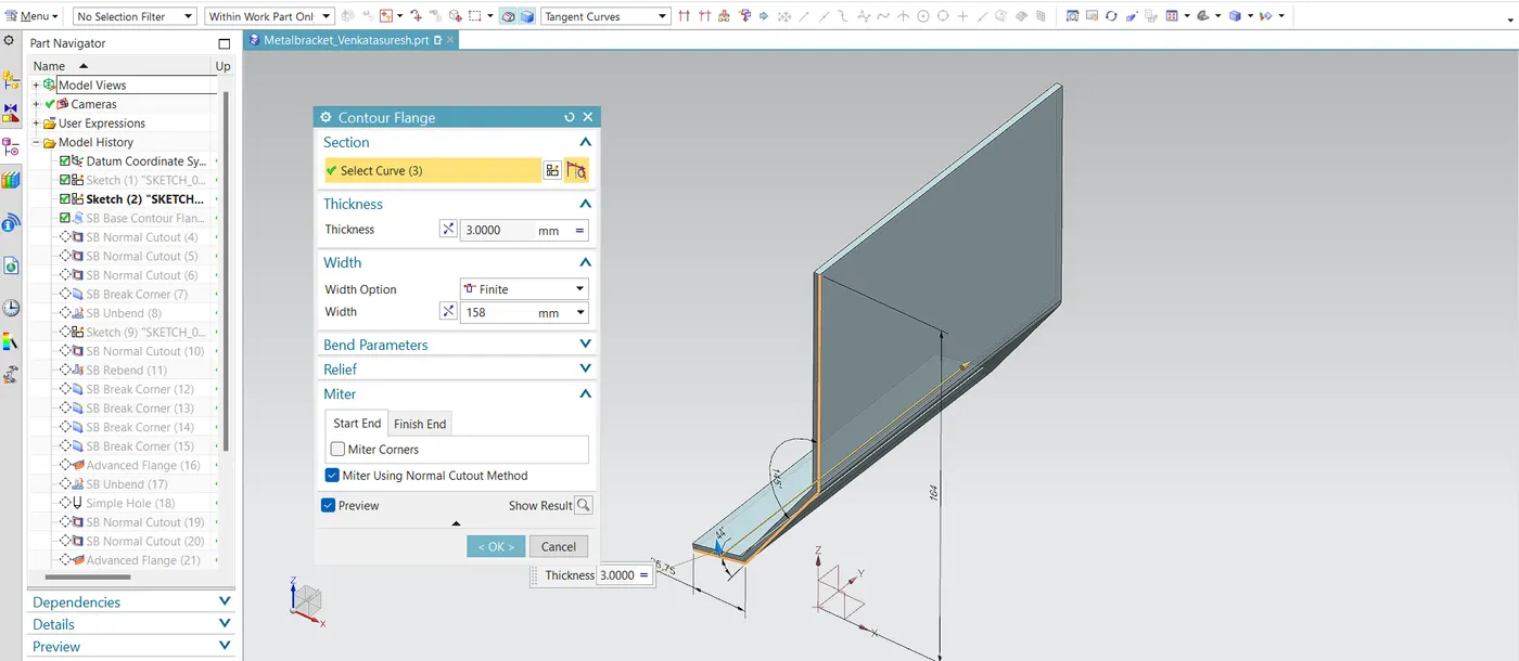
In Siemens NX sheet metal contour flange command use to create a base feature by extruding a sketch along a vector, or adds material by sweeping a sketch along an edge or chain of edge.
From the menu: Insert -> Bend -> contour flange.
Contour flange creation:
The contour flange is a flange created using the open sketch created in a plane. It is different from regular flange because it can be created in any shape and it does not require choosing the edge of any tab or existing flange. It can be at any position or at any angle. For this bracket design, a contour flange is created using the earlier sketch as the curve.
3.Normal cutout:
Using the NORMAL CUTOUT tool, we remove the material from the required location.
Normal cutout creation:
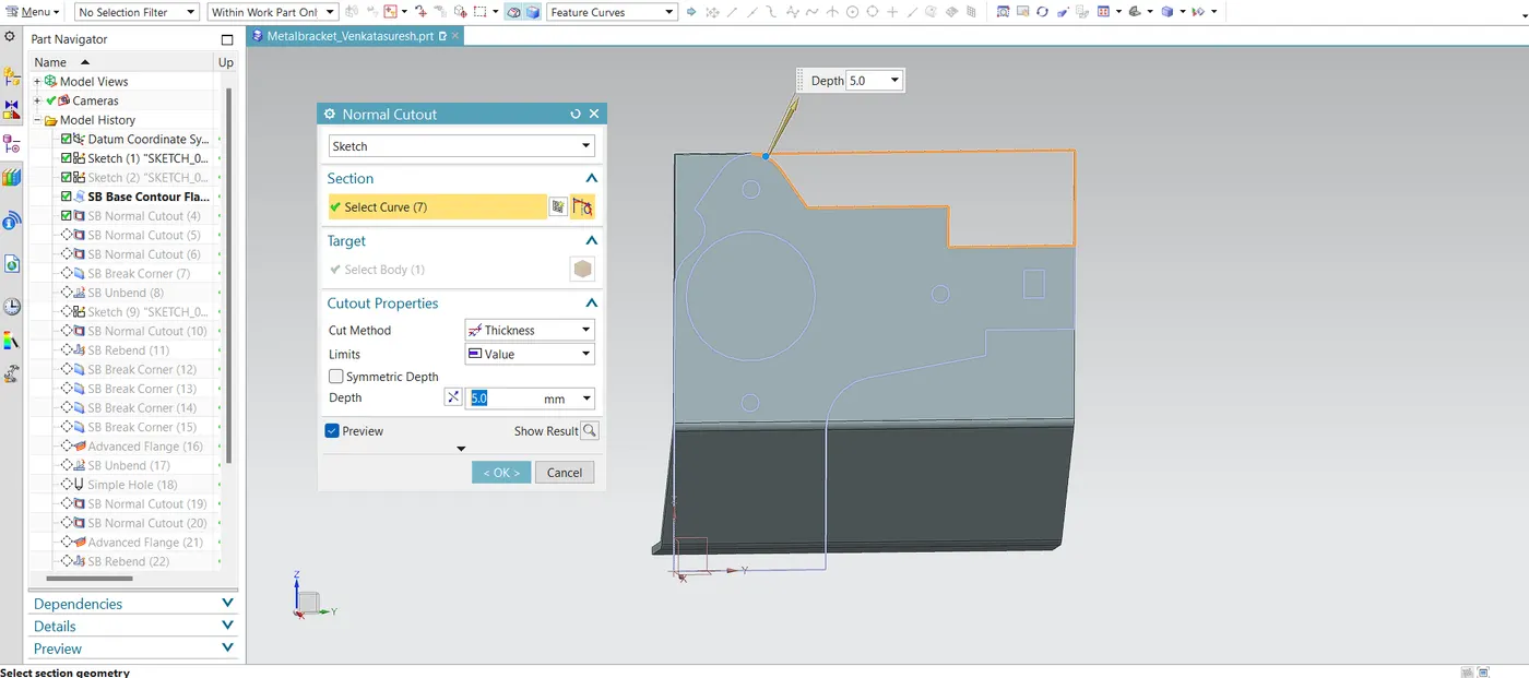
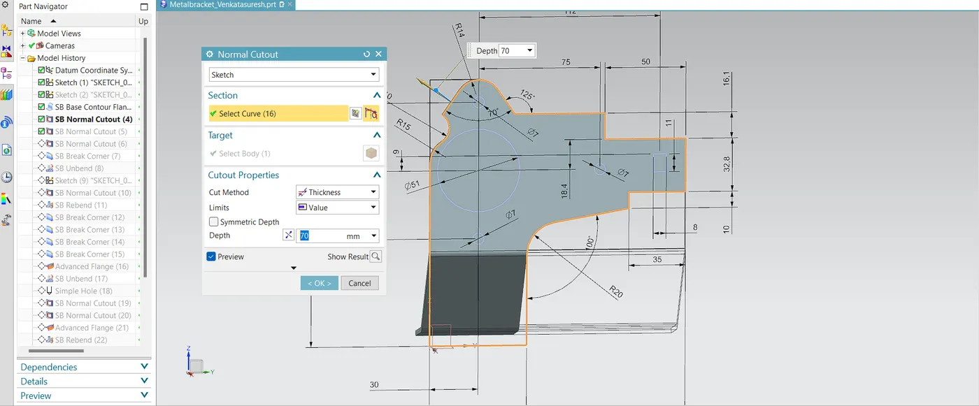
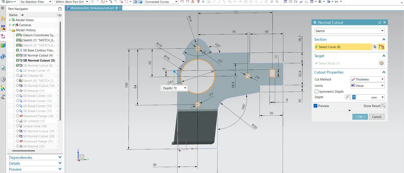
It cuts away the material at the right angle with respect to the sketch plane. A closed sketch is created on the YZ plane to cut away the unnecessary material. Sketch 1 is projected and the required closed contours are sketched wherever cuts required. Then the operation normal cut out is carried out.
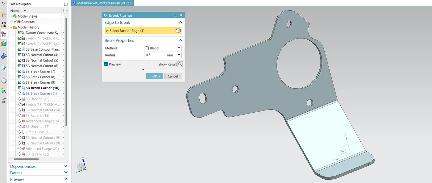
4.Break corner:
Break corner and chamfer tools are used to make some changes over sheet metal body. Both the tools provide a different activity in creation of the parts.
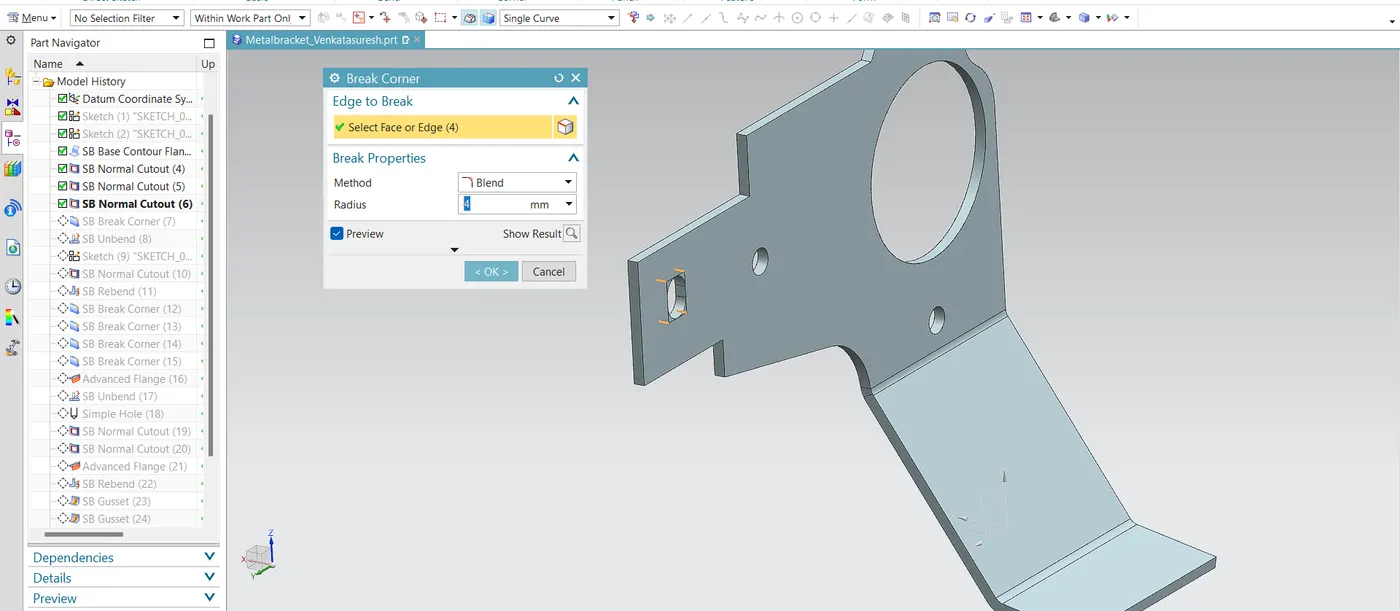
Rounds or chamfers a sharp corner of a tab or flange. Here by using this tool we can do two different operations.
One is Forming Bend to part and secondary is Forming chamfer.
Bend: Completely formed with radius and creates smooth edges.
Chamfer: This tool is applicable by distance and creates sharp edges.
Break corner creation:
Select the edges want to apply the break corner command.
5.Unbend:
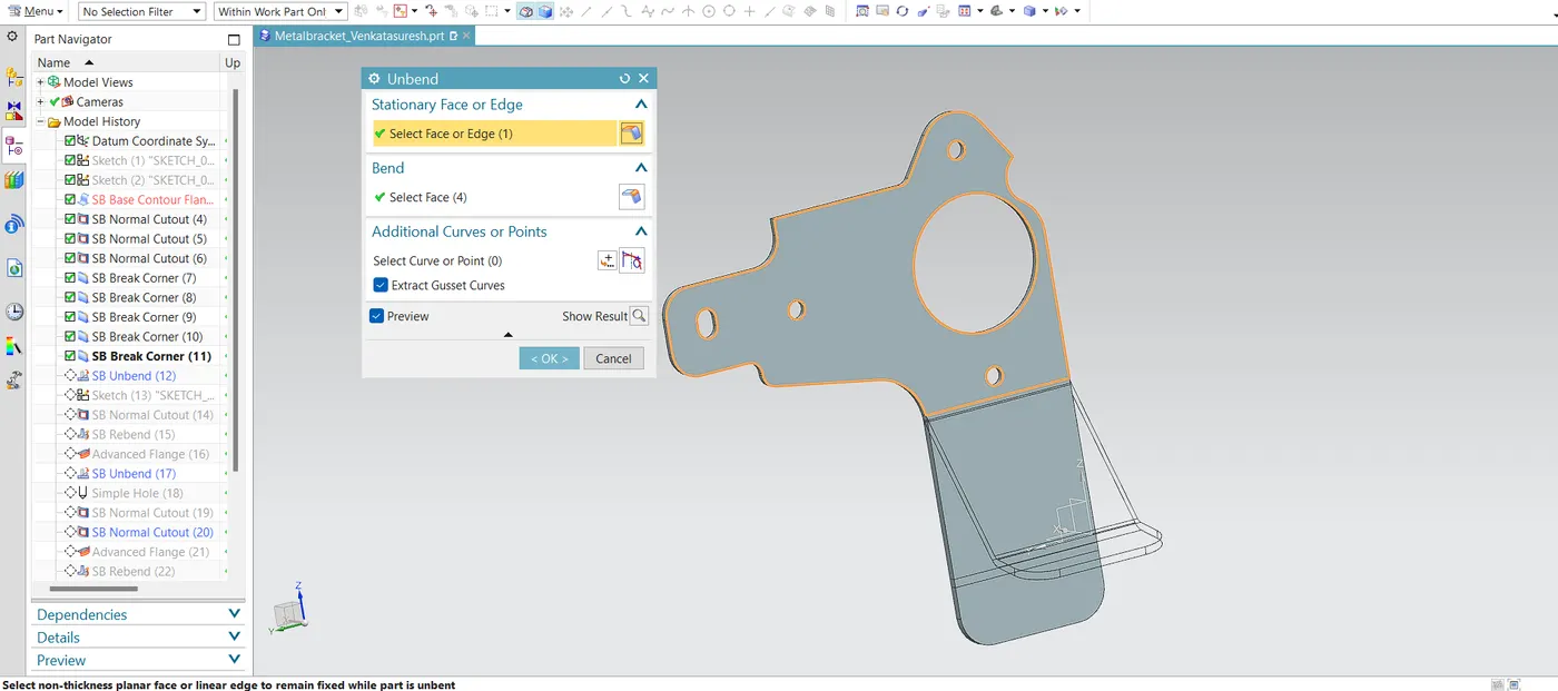
As the tool name indicates the bend tool is used to bend the sheet metal bodies and the unbend is vice versa of the bend tool, it is to unbend the bent regions.
The part is unbend to create additional features such as hole, dimple, beads which otherwise cannot be created if it not unbend. Moreover, it also helps to check whether the part is a sheet metal or not. If the part is unbending then it is a sheet metal otherwise it is still a solid body or dumb body.
Unbend creation:
Select the stationary face and select the bend faces to form the unbend.
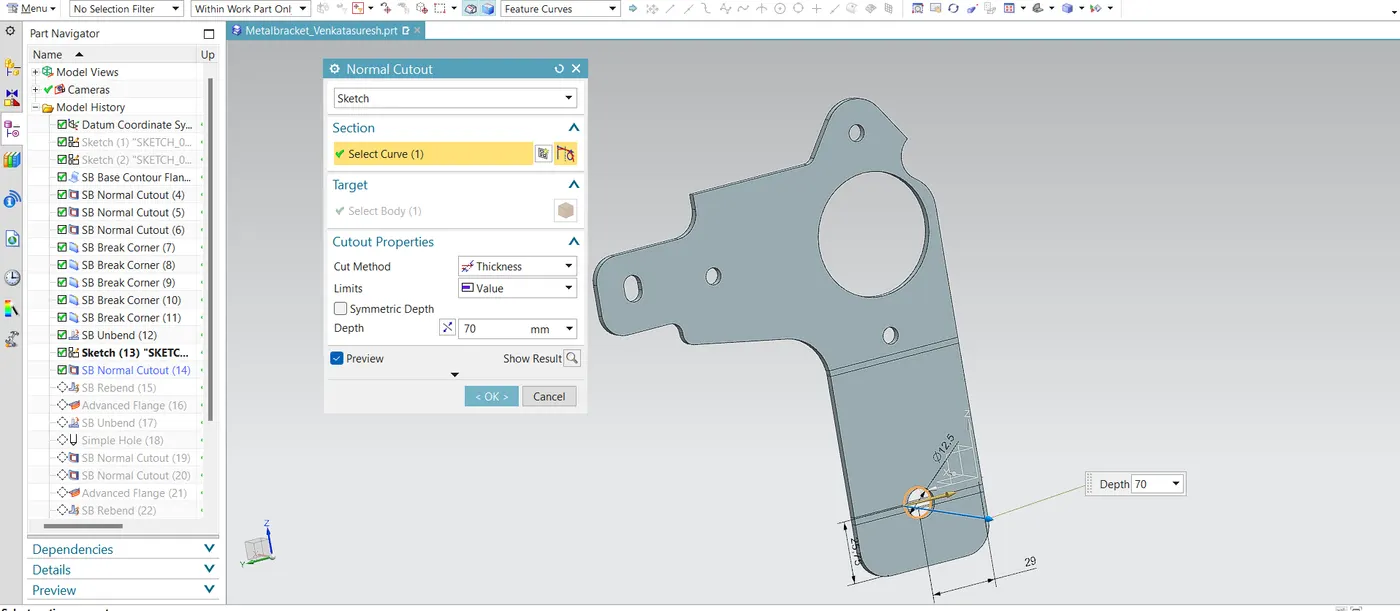
6.Normal Cut Out creation:
A profile for the normal cut out is created. Using the command normal cut out command the material is removed. This operation is done through predefined sketch.
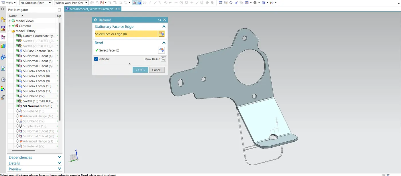
7.Re-bend:
As the tool name indicates the bend tool is used to bend the sheet-metal bodies and the re-bend is vice versa of the bend tool, It is to re-bend the un-bended regions.
Re-bend creation:
Open the re-bend command and drag the cursor over the faces to be re-bend.
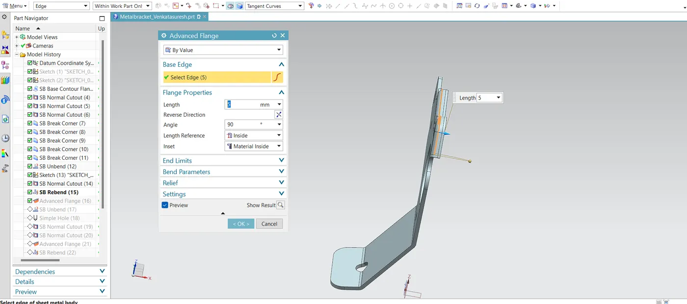
8.Advanced Flange:
Unlike base simple base flange, the advanced flange can create flange from any edge which can be either curved or straight line, open or closed profile. This allows creating a flange with a match face also.
Advanced flange creation:
For this bracket, the advanced flange is created at the upper portion with proper parameters as shown.
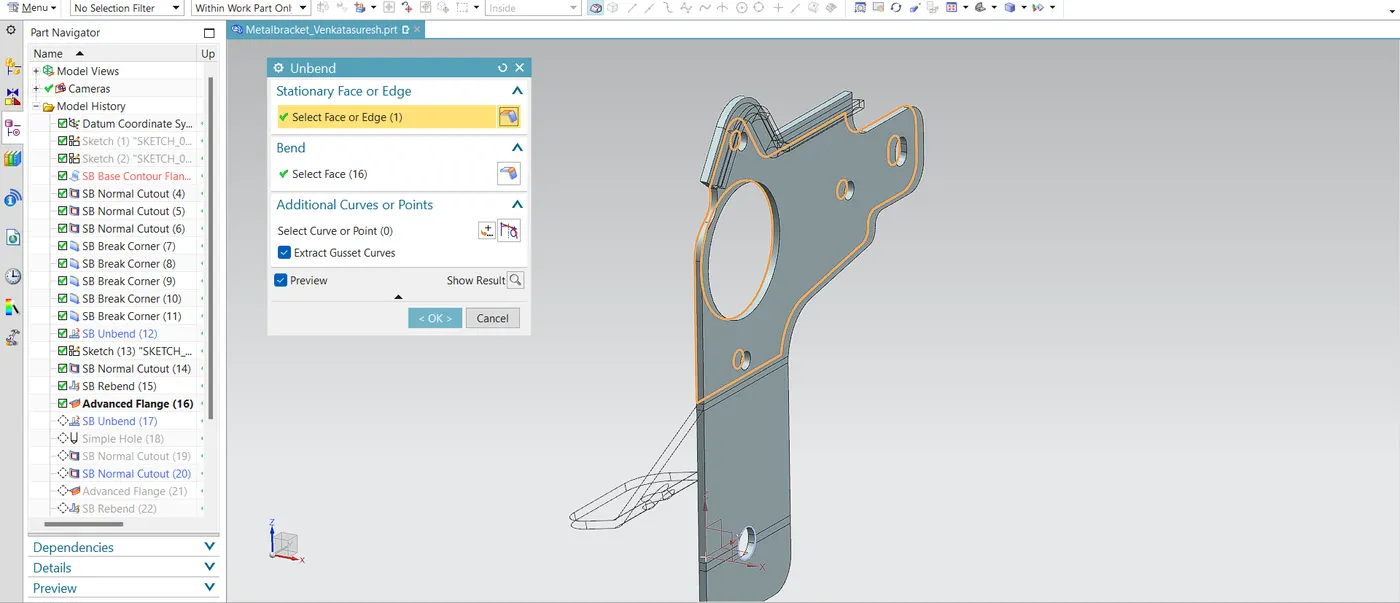
9.Unbend creation:
Again, the unbend feature is applied after which a couple of features are applied.
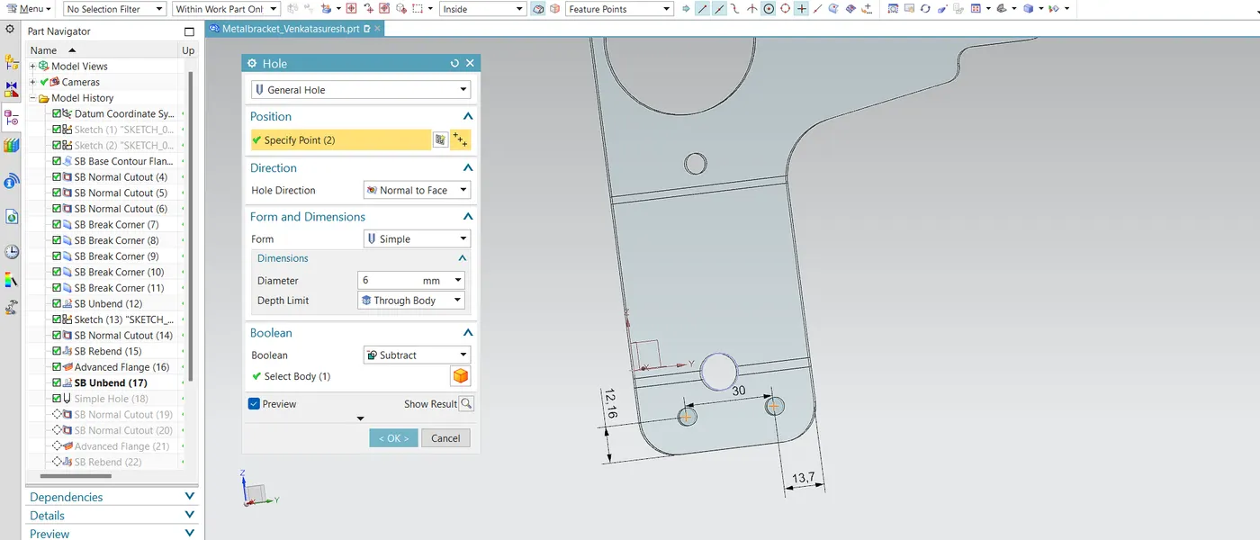
10. Holes creation:
The additional features holes are also created. Hole command is available in the sheet metal workbench of the NX CAD.
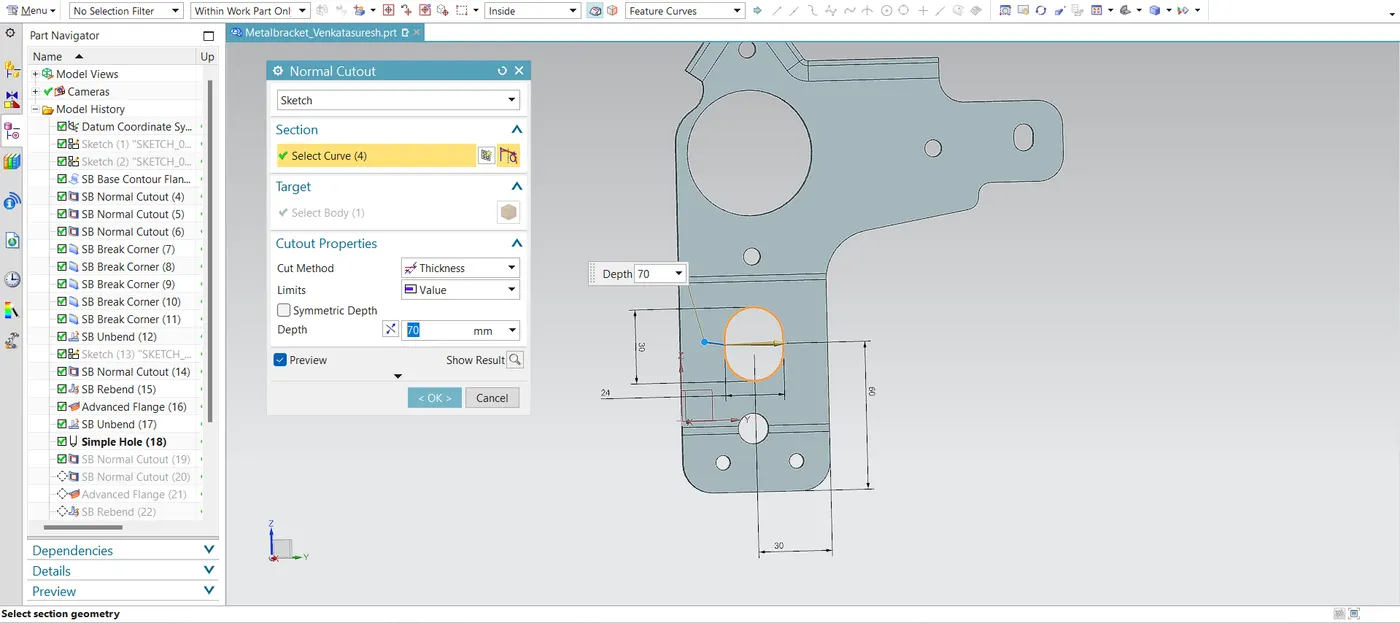
11.Normal Cut-out creation:
Again, a couple of normal cut-outs are carried out in the unbent state as shown below.
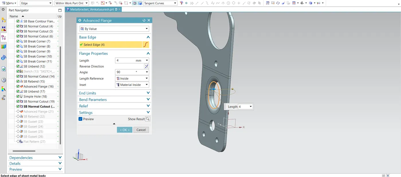
12.Advanced Flange creation:
Again, an advanced flange is applied at the edge of the normal cut-out created in the above step.
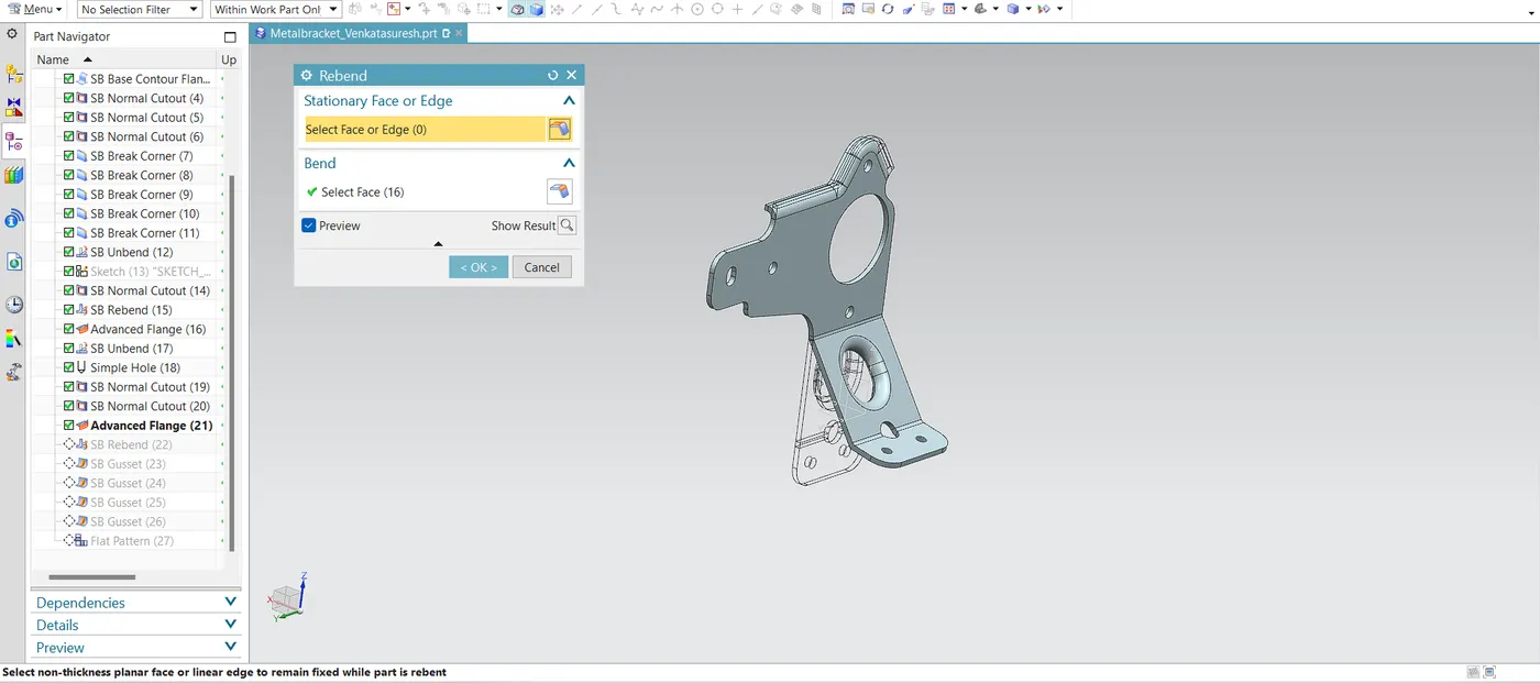
13.Re-bend creation:
All the features added after the unbend feature are added in the unbend state itself. After the addition of sketches and additional features are completed, the sheet metal component has to be re-bent to the required position. This is done using the re-bend feature and selecting all the bends in order or by box selection.
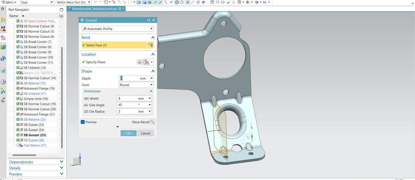
14.Gussets:
Gussets are the strength stiffening features. They add strength and stiffness to the sheet metal parts.
Gusset creation:
The face and the plane are selected for the gussets to be created and the profile is generated. The profile can be automatically generated or the sketch can be created.
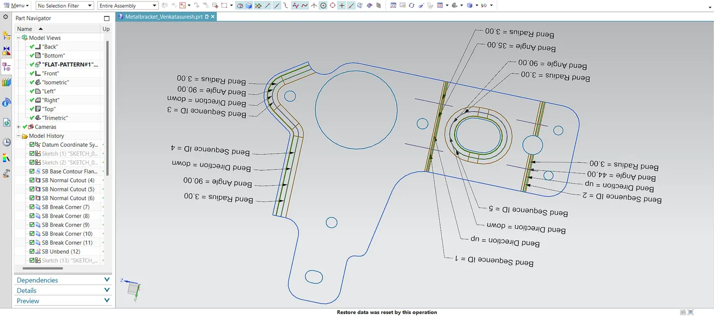
15.Flat Pattern:
Flat pattern is the representation of the entire sheet metal component in the 2D form of the flat sheet metal with all the bends, cut-outs, holes, and additional features in the form of lines or edges. The flat pattern ensures the ability to cut the sheet metal out of the raw sheet metal plate. It removes the possible errors such as interference or collision within the same component.
Flat pattern creation:
Open the flat pattern command and select the flat face as reference and apply…
Views:
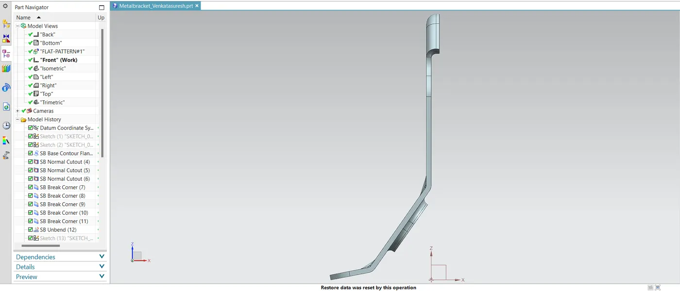
1.Front view:
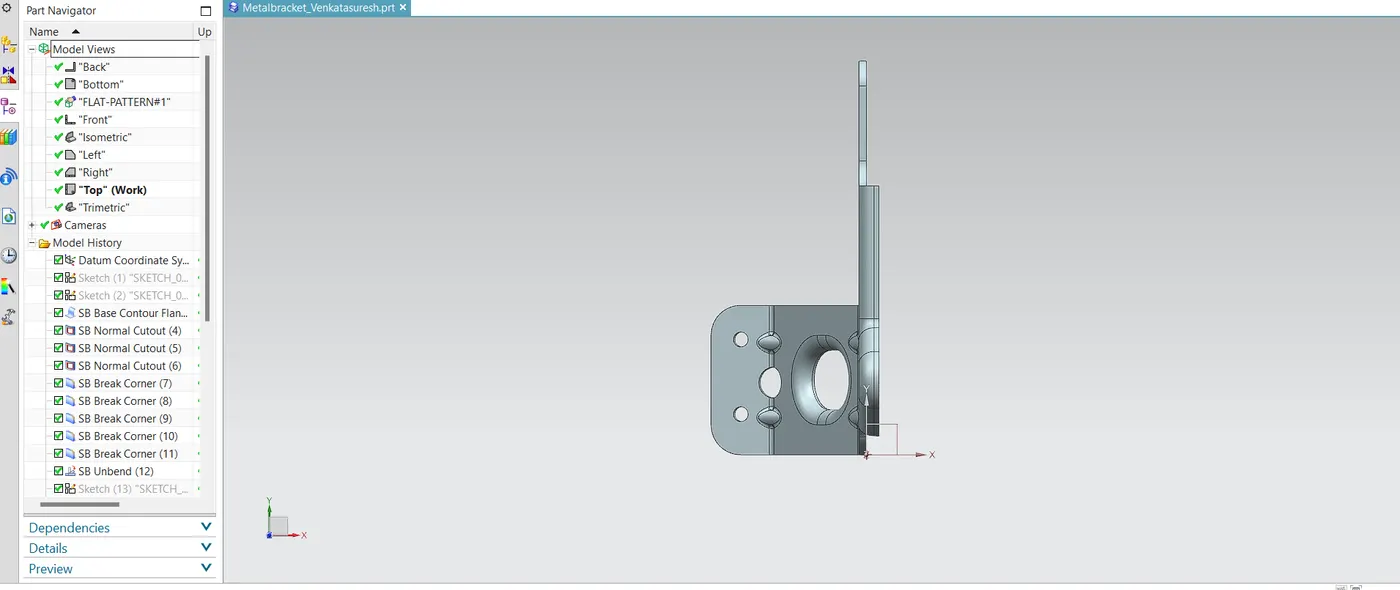
2.Top view:
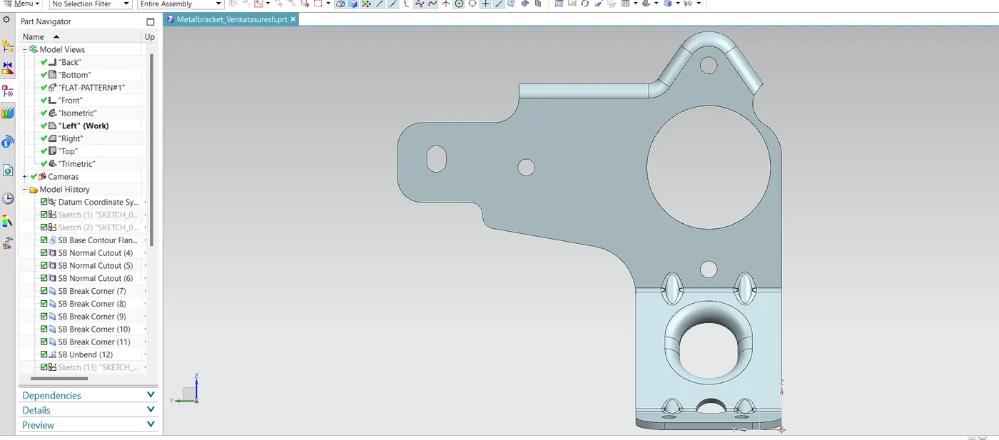
3.Side view:
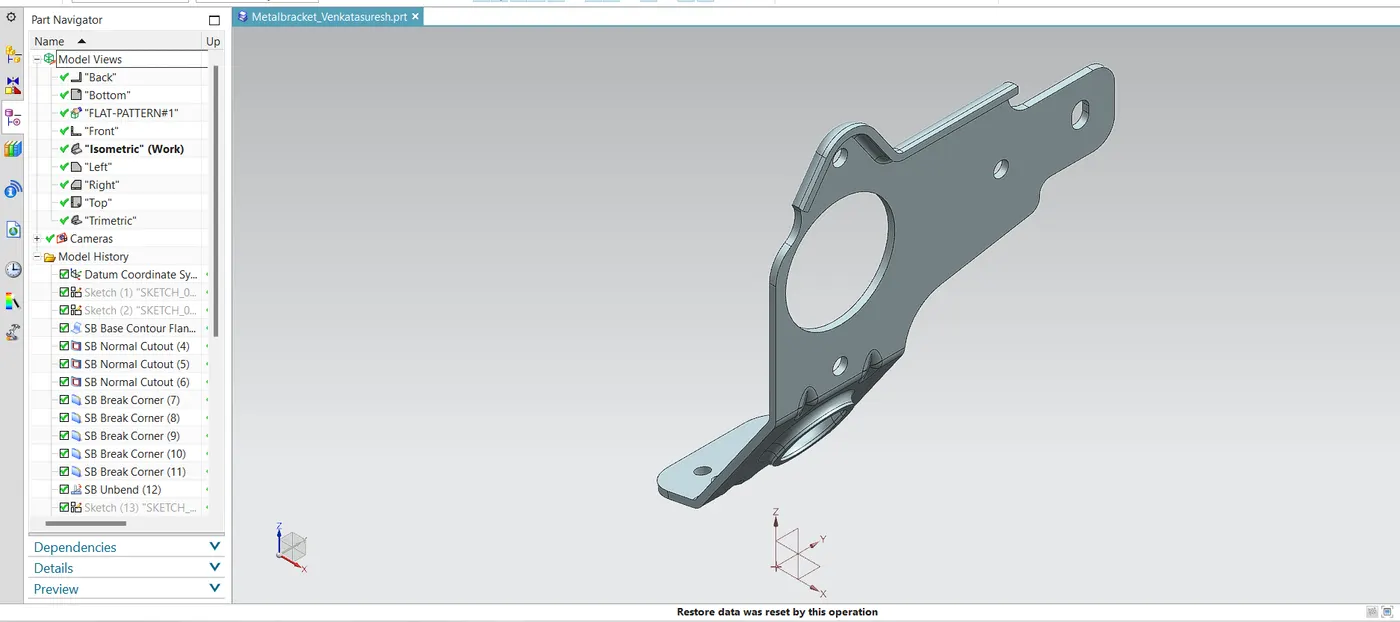
4.Isometric view:
Drafting:
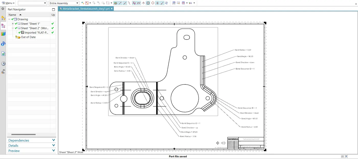
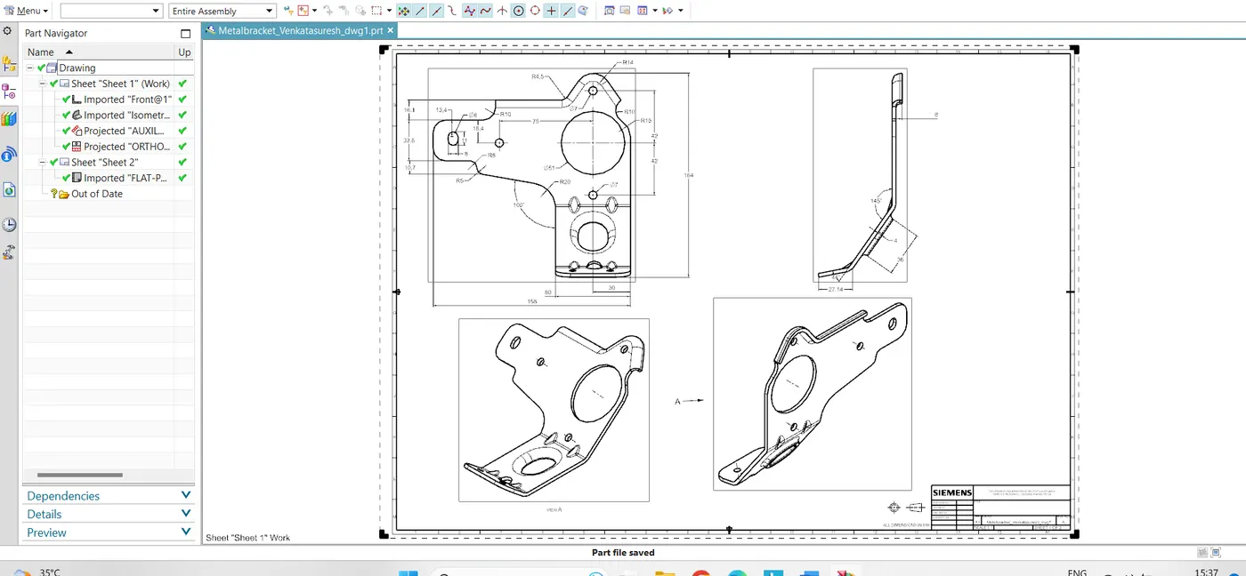
We can create 2D drawing sheets in NX CAD from the sheet metal component designed. For that we have to follow the process below:
Application >> Drafting >> Base View >> In model view to use - FLAT PATTERN created >> Adjust appropriate scale >> Drawing Sheet formed >> Give Proper Dimensions.
Drawing sheet:
Detailed view:
CONCLUSION:
- Finally, the Metal bracket of the sheet metal is designed on the Siemens NX12.0
- The tools and features used for the Metal bracket II is learned.