Wiring harness routing & packaging Rules Week 3 Challenge
Q1. Download following cad data & define it as Electrical support using Electrical Part design Workbench. Define all the necessary properties. P clamp
Note: if you face any issue with point definition, point selection, Right-click on the point definition window and use the reset option.
Answer:
process: After downloading the component go to the mechanical part design workbench.
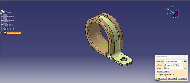
Create two points one as entry and another as exit point. Create planes corresponding two points and another plane for base.
After above steps Switch to Electric part design. Click on support definition ->select part -> select entry point -> select entry plane, exit and base plane.
Again, click on support definition -> select part -> select exit point -> select exit plane and base plane as secondary plane is automatically taken.
Creating references
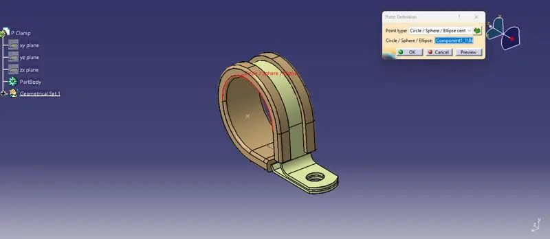
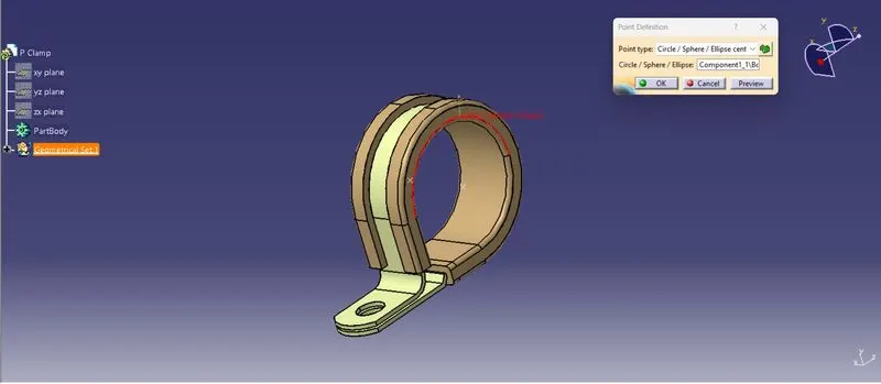
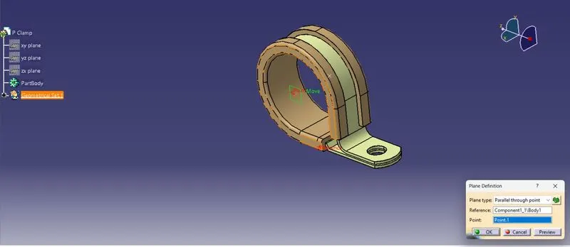
Define as electrical part using electrical part bench & after giving entry and exit point the following changes will occur in tree
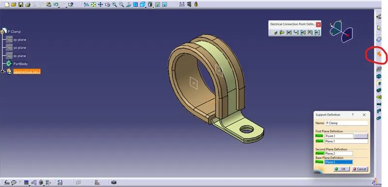
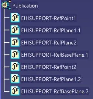
After above steps added the part to support catalogue
Q2. Download following Back shell cad data & define it as Electrical back shell using Electrical Part design Workbench. Define all the necessary properties.
Tyco 1738312-1 https://www.te.com/usa-en/product-1738312-1.html
Answer:
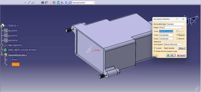
In this question after downloading the back shell from the provided URL.
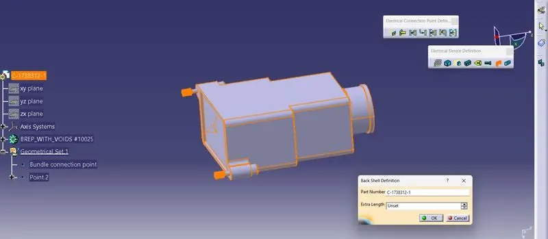
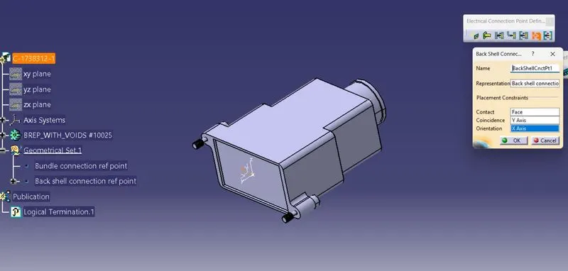
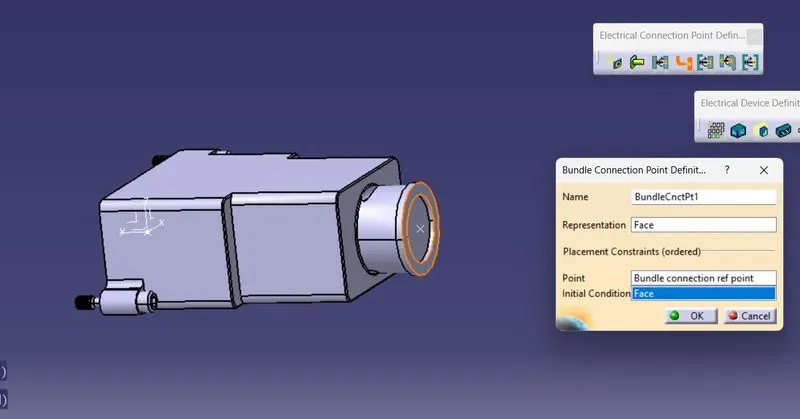
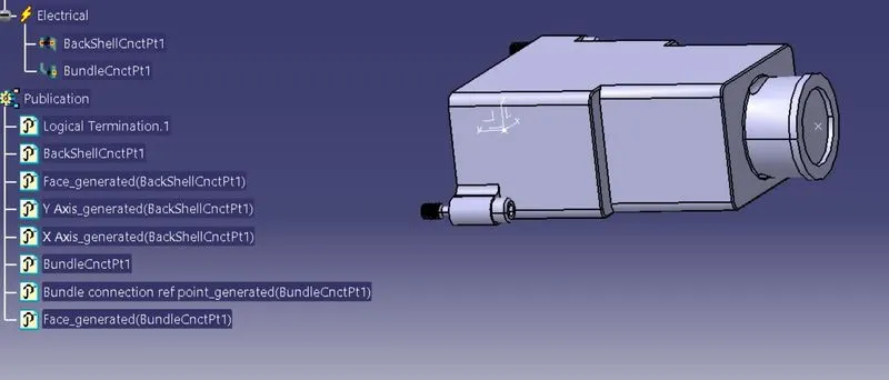
2ndstep is providing Geometry parameters. In 3rd step we define as back shell using electrical device definition tool bar at Electrical part design workbench. In 4Th step we define back shell connection point & Bundle connection point by using Electrical connection point definition tool bar.
1st step has to create the back shell entry point, Axis system & Bundle connection point
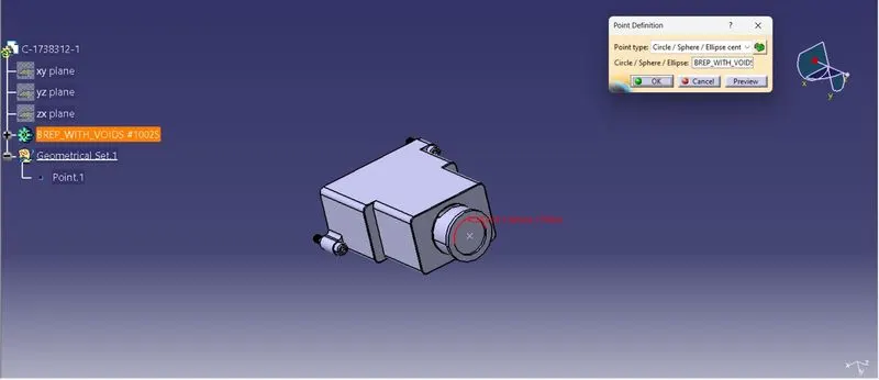
2nd Step has to define as back shell & define back shell connection point, Bundle connection point at Electrical part design
Q3. Create Following Corrugated tubes & add them in Catalogue under “Slit COT” family.
|
Name |
ID (mm) |
OD (mm) |
Thickness (mm) |
|
15mm COT |
12 |
15 |
1.5 |
|
20mm COT |
17 |
20 |
1.5 |
|
35mm COT |
32 |
35 |
1.5 |
|
10mm COT |
7 |
10 |
1.5 |
|
5mm COT |
3 |
5 |
1 |
Answer: Take new part file and save file name
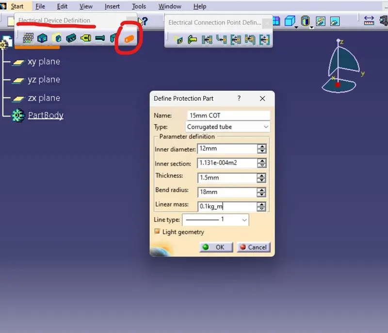
- Switch to Electrical part design
- Select Define protection Part
- Click on part (on file name in specification tree)
Provide given parameters and bend radius as 1.5 x Outer Día
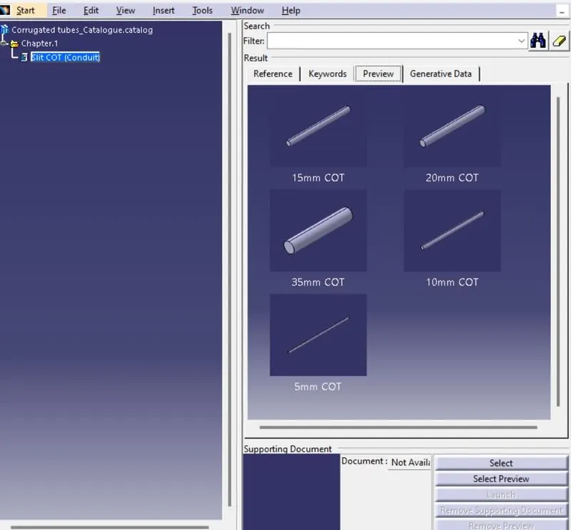
First, we need create the catalogue file than we need to create components. In catalogue using Add Family Creating Catalogue library file with family name Slit COT
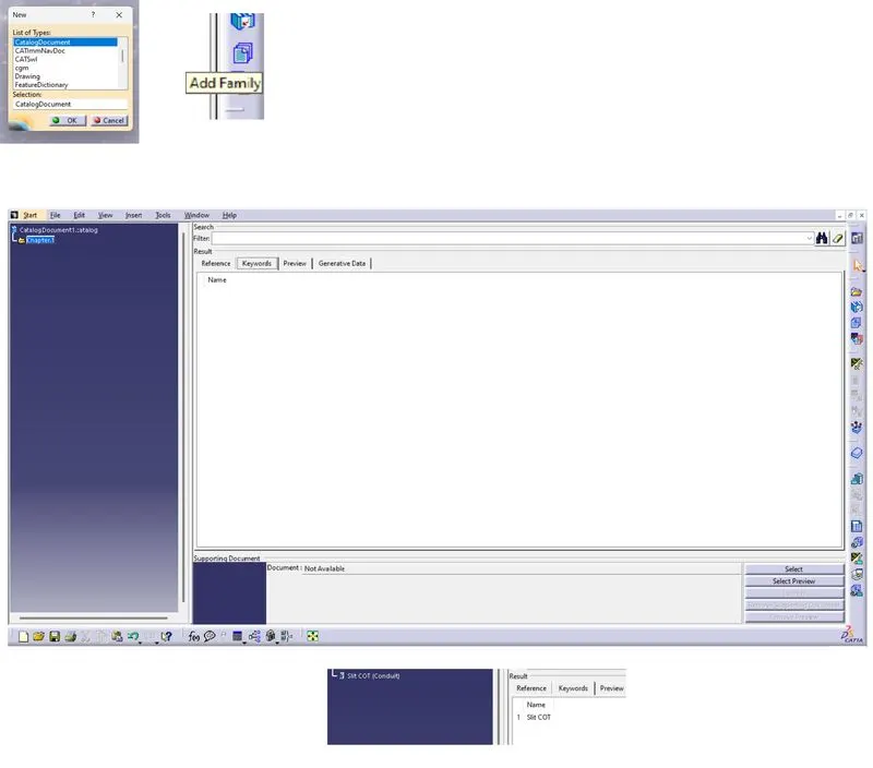
Creating part with given data
Adding created part to library
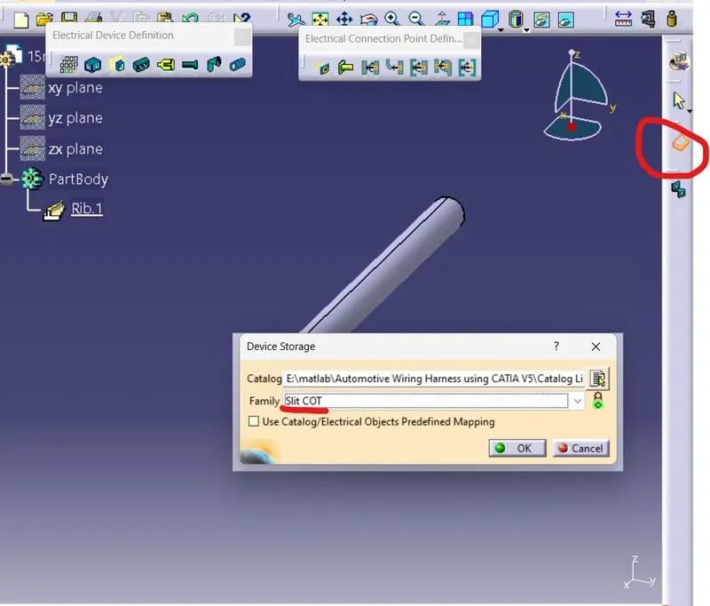
After adding all parts to catalogue.