Wiring harness design in CATIA V5 - 3D modeling Week 2 Challenge
Downloaded from the links that provided in question. Converted from IGS files to CATIA and
Save to the directory as CATIA part.
To make it as electrical component first we create or provide required geometrical parameters like point, Co-ordinate system(axis) at Mechanical part design workbench using reference toolbar. After the creation of references the workbench has to be shifted to Electrical part design where we can give electrical part definition to component. Like defining as connector, mounting equipment etc using Electrical Device definition toolbar. After that we provide electrical connection point definitions like cavity point, bundle connection point, connector connection point etc.
Deutsch DT06 – 08SA:
Creating midpoint on the contact face which will be normal to wire bundle insertion.
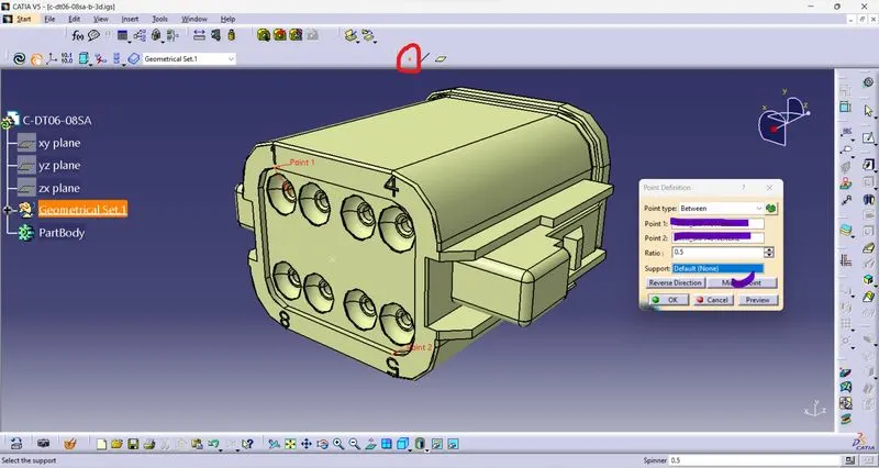
Creating a point at mating connecter connection side
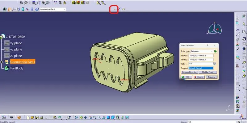
Creating an axis system at mating connecter connection side is not specific but it should be maintained same for all the components of mating.
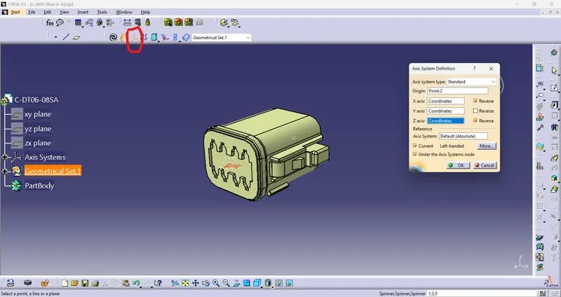
Switching to Electrical part design
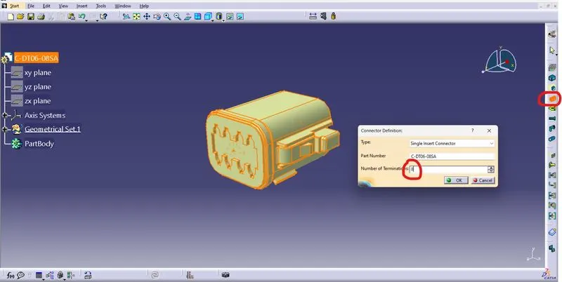
Defining as connector by Using “Electrical Device definition” toolbar and providing the number of terminations
Defining bundle connection point
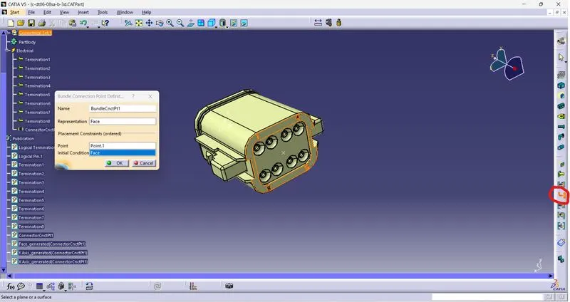
The changes occurred in tree after defining bundle connection point
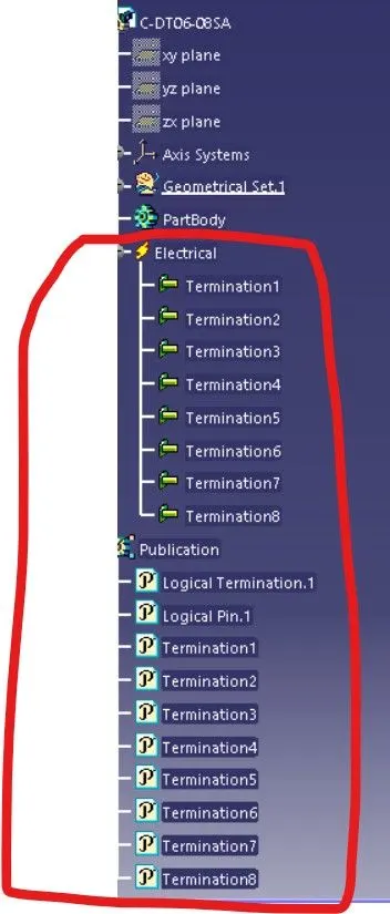
Defining mating connector connection point
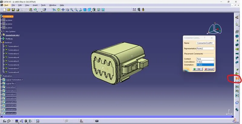
The changes occurred in tree after defining mating connector connection point
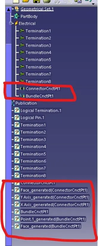
these are the properties of electrical definitions.
This connector does not have cavity, so we wouldn’t provide the cavity connection definitions.
Tyco 174357-2:
This connector has cavity so we have provided cavity definition for this part and slides as follows
Creating bundle connection point & connector connection point at part design workbench.
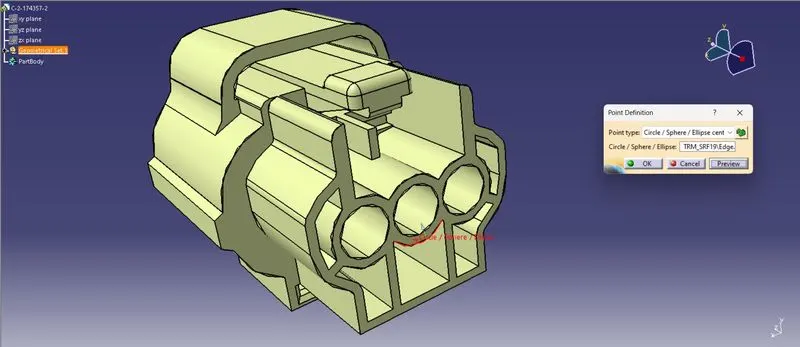
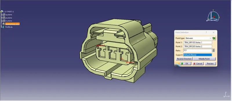
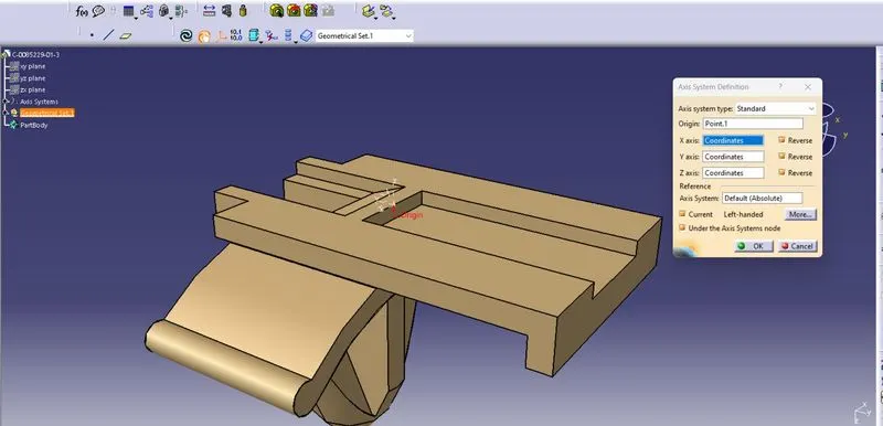
Creating an axis system at mating connecter connection side.
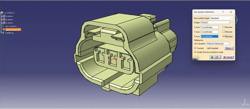
Creating a point & an axis system at cavity connection side
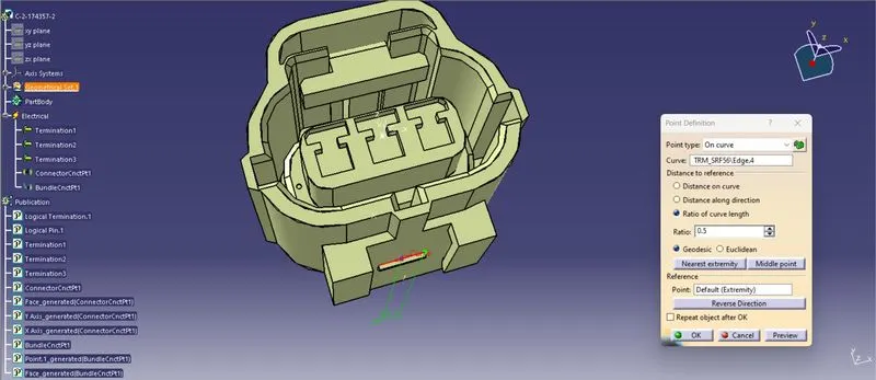
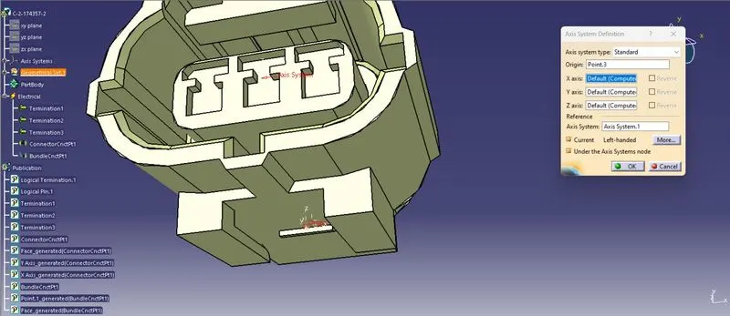
After creation of above references shift the workbench to Electrical part design workbench to provide electrical definitions.
Defining as connector, providing number of terminations.
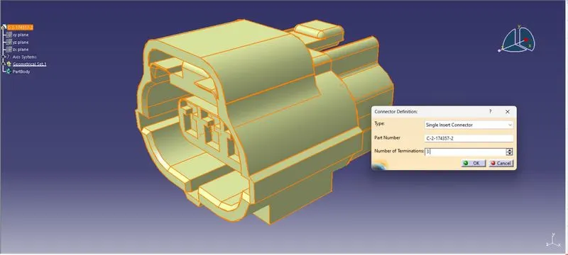
Defining bundle, connector connection point & cavity connection point.
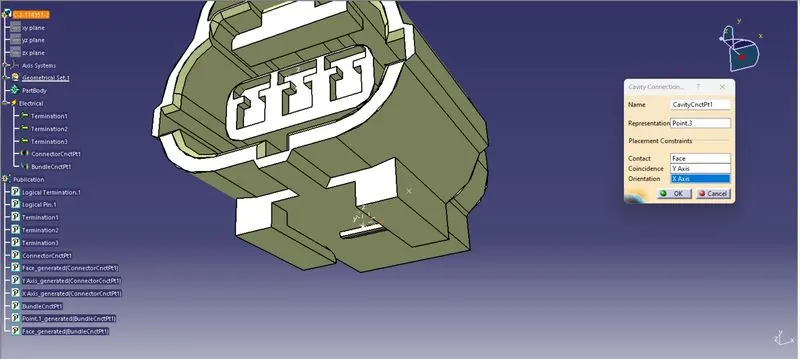
Tyco 85229-1:
Creating reference geometrical parameters & definitions are provided as follows:
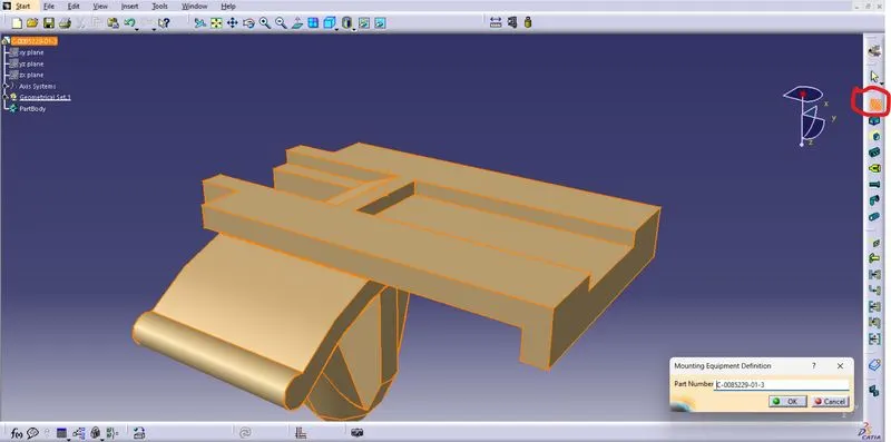
This is a mounting type electrical device and contains cavity.
Defining as mounting equipment:
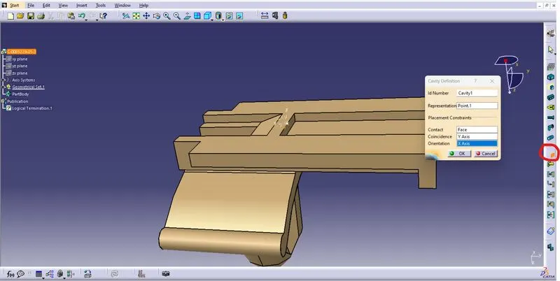
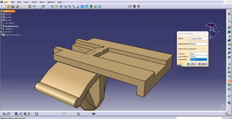
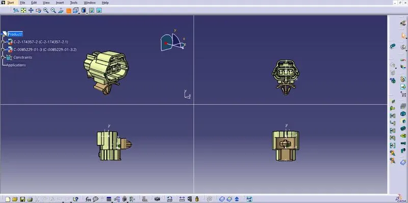
After completing the creating references and defining electrical equipment saved to catalogue library. The details are provided as cad files. Then imported to the product file and made electrical connections in Electrical assembly design.
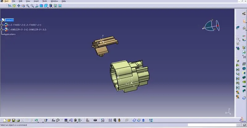
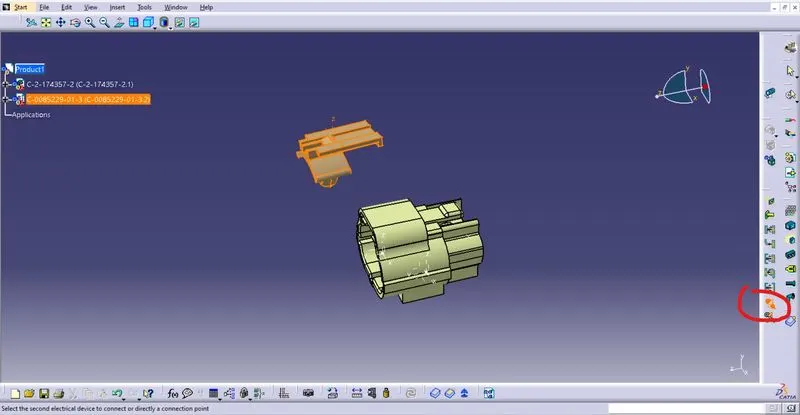
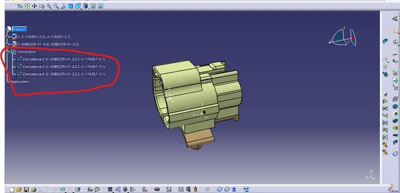
After providing electrical connections the following constrains added in tree. The cavity connection symbol also created at cavity point.