Roof Design
Automobile Roof Design
Introduction
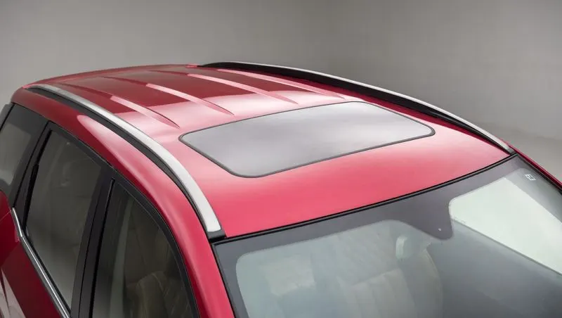
The roof of an automobile serves as a protective structure that shields the passengers and the interior of the vehicle from external elements such as rain, wind, sun, and snow. It also provides structural strength to the overall automobile design. Automobile roofs are typically constructed using lightweight materials such as steel, aluminium, or composite materials like carbon fiber. The roof is designed to be aerodynamic to reduce wind resistance and improve fuel efficiency.
The roof's structure is reinforced with a combination of pillars, cross members, and other supports to ensure that it can withstand overhead forces like snow or wind loads. The pillars are the vertical structures that support the roof and are typically located at the front, middle, and rear of the vehicle. The cross members are the horizontal structures that connect the pillars and provide additional support to the roof.
Roofs can also have additional features like sunroofs or moon roofs, which allow passengers to enjoy natural light and fresh air while driving. Some cars also come with retractable or convertible roofs, which can be folded down or removed completely to give passengers an open-air driving experience. Overall, the roof is an essential component of an automobile, providing protection and structural integrity to the vehicle and its passengers.
Curvature Study:
The curvature study on roofs involves analyzing the shape and structure of a roof to ensure that it can withstand various external forces such as wind, snow, and rain. One of the methods used to predict the shape of a roof is the Bow roof prediction calculation. This method involves calculating the curvature of the roof based on the span, rise, and the amount of bow required.
The curvature study is important, as it helps ensure that roofs are structurally sound and can withstand the forces they will be exposed to. It also plays an important role in the design process, as it affects the overall aesthetic appeal of the building.
Manufacturing Techniques:
Some of the common manufacturing techniques are:
-
Stamping: This involves the use of a large press to stamp the roof panel into the desired shape. The process involves using a die, which is a specially designed mold that the sheet metal is formed into. This method is commonly used in mass production.
-
Roll forming: This involves the use of a series of rollers to gradually shape the metal into the desired shape. The process is slower than stamping but allows for more complex shapes to be produced.
-
Injection molding: This method involves injecting molten plastic into a mold to produce the desired shape of the roof. This technique is commonly used in the production of plastic roofs.
-
Carbon fiber reinforced plastic (CFRP): This technique involves the use of lightweight materials such as carbon fiber to produce a strong and lightweight roof. CFRP roofs are commonly used in high-end sports cars and luxury vehicles.
Different types of reinforcements for roof of a car :
-
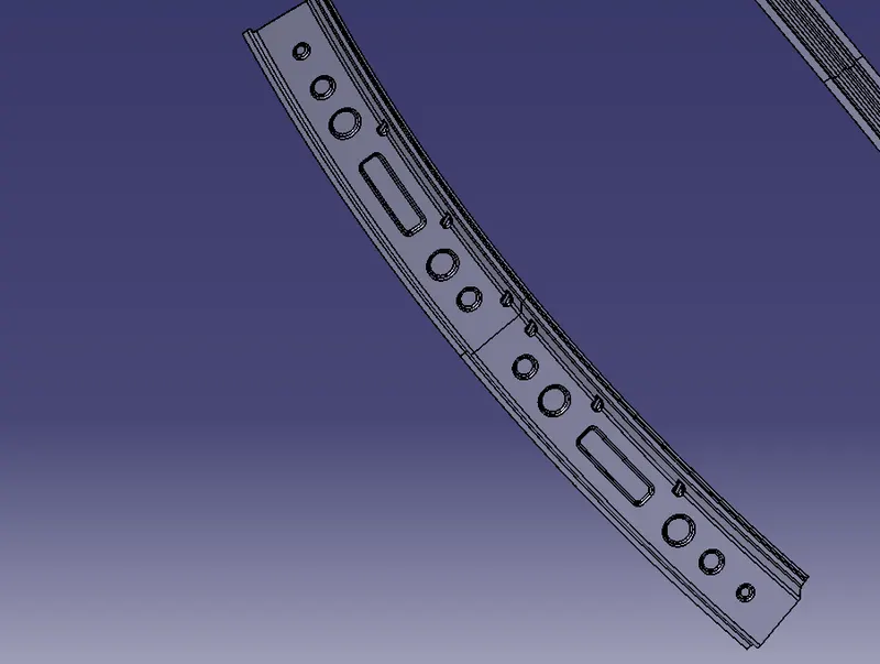
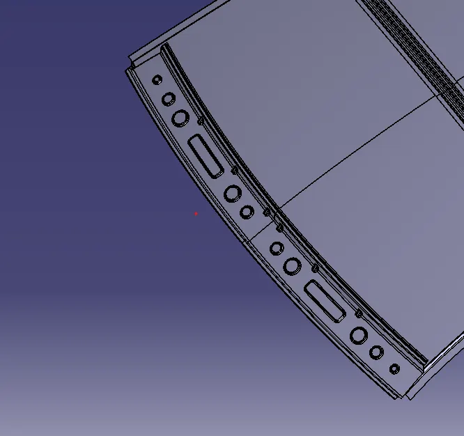
Front roof rail: The front roof rail is a structural component of the roof located at the front of the vehicle. It typically runs from the A-pillar to the B-pillar and provides support for the front of the roof.
-
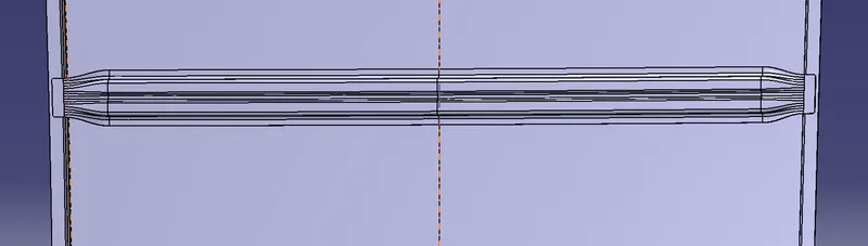
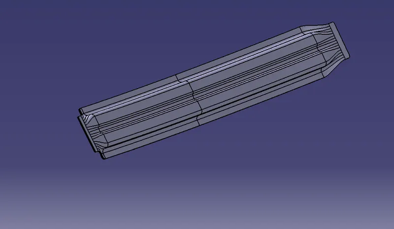
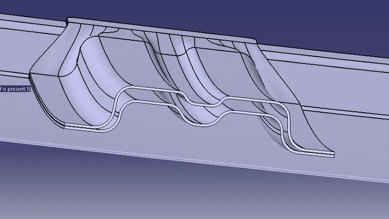
Central roof rail: The central roof rail is another structural component of the roof that runs along the centerline of the vehicle. It provides additional support and rigidity to the roof structure.
-
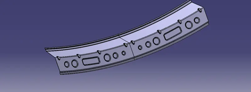
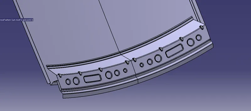
Rear roof rail: The rear roof rail is located at the rear of the vehicle's roof and provides support for the rear section of the roof. It typically runs from the B-pillar to the C-pillar.
-
Bow roofs: Bow roofs are a type of roof design that features a gentle curve or arch in the roofline. The curve is created by a series of bow-shaped supports that run from one side of the roof to the other. Bow roofs were commonly used in classic cars and are still used in some modern vehicles.
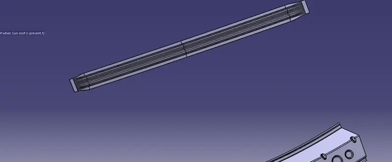
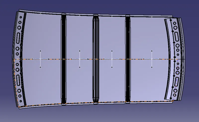
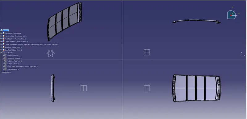
Draft analysis:
Outer Roof -
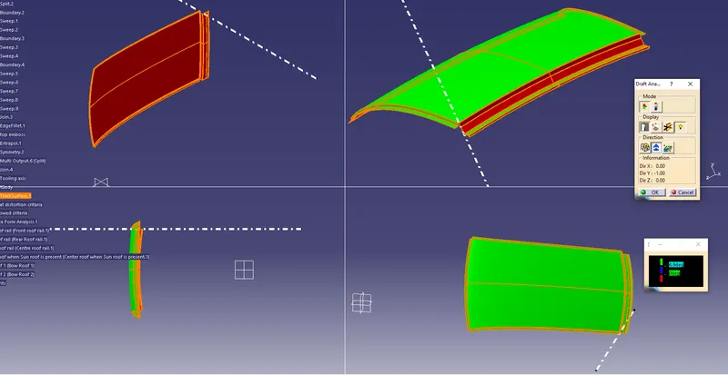
Front Roof Rail -
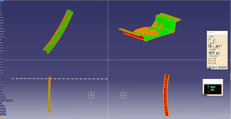
Rear Roof Rail -
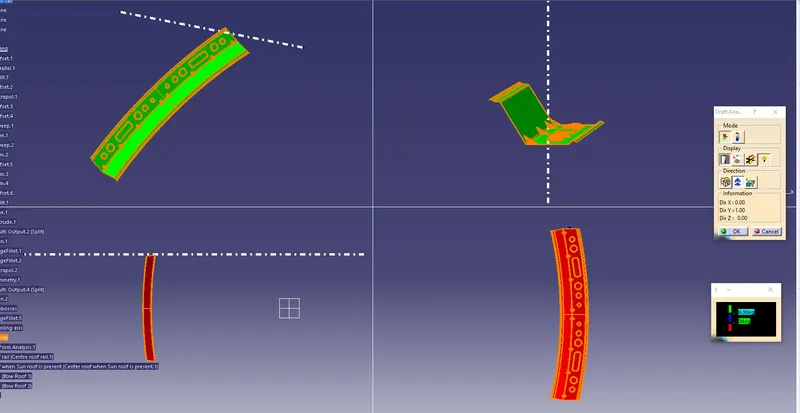
Center Roof Rail -
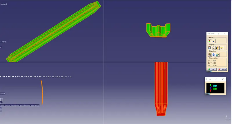
Center Roof Rail when sunroof is present -
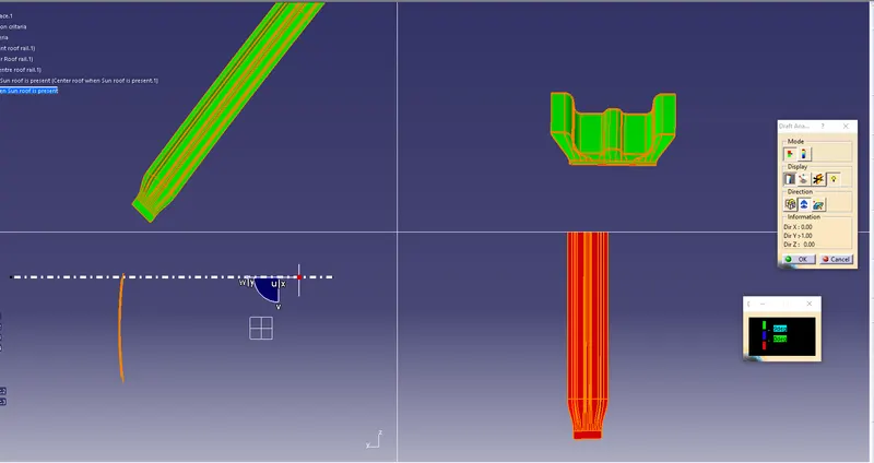
Bow Roof Rails -
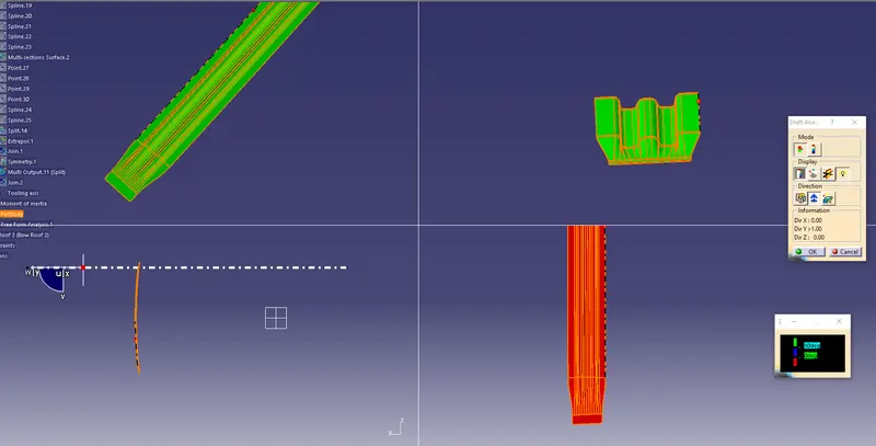
Heat distribution criteria:
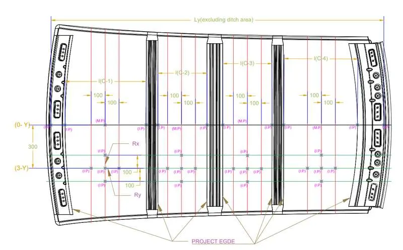
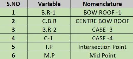
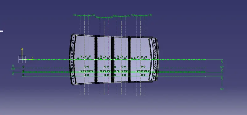
Prediction Formula :
W = [1.73 x 10^(-3) x L] + [1.85 x 10^(-8) x (R^2)/t] + [ 1.10x10^(-3) x l] - 2.68
Where,
L = Roof Length in X-Direction[mm](Roof dimension in 0-Y)
R = Roof curvature
R = 2(Rx*Ry)/(Rx+Ry)
Rx = X curvature
Ry = Y curvature
t = Roof plate thickness [mm]
l = Bow Roof Span [mm]
Judgment Condition:
OK< 2.7
From measuring the part we get,
L = 1925 mm
t = 0.75 mm
CASE - 1
Rx = 5707.009 mm
Ry = 2909.075 mm
l = 486.836 mm
R = 2(5707.009*2909.075)/(5707.009+2909.075)= 3853.750 mm
Therefore,
W1 = [1.73 x 10^(-3) x 1925] + [1.85 x 10^(-8) x (3853.750^2)/0.75] + [1.10x10^(-3) x 486.836] - 2.68
W1 = 1.552 mm
CASE - 2
Rx = 4864.083 mm
Ry = 6632.11 mm
l = 327.843 mm
R = 2(4864.083*6632.11)/(4864.083+6632.11)= 5612.141 mm
Therefore,
W2 = [1.73 x 10^(-3) x 1925] + [1.85 x 10^(-8) x (5612.141^2)/0.75] + [1.10x10^(-3) x 327.843] - 2.68
W2 = 1.787
CASE - 3
Rx = 4072.957 mm
Ry = 10100.832 mm
l = 326.386 mm
R = 2(4072.957*10100.832)/(4072.957+10100.832)= 5805.117 mm
Therefore,
W3 = [1.73 x 10^(-3) x 1925] + [1.85 x 10^(-8) x (5805.117^2)/0.75] + [1.10x10^(-3) x 326.386] - 2.68
W3 = 1.840
CASE - 4
Rx = 3348.906 mm
Ry = 14140.258 mm
l = 476.562 mm
R = 2(3348.906*14140.258)/(3348.906+14140.258)= 5415.283 mm
Therefore,
W4 = [1.73 x 10^(-3) x 1925] + [1.85 x 10^(-8) x (5415.283^2)/0.75] + [ 1.10x10^(-3) x 476.562] - 2.68
W4 = 1.897
So, we have: W1 = 1.552< 2.7, W2 = 1.787< 2.7, W3 = 1.840<2.7, W4 = 1.897<2.7
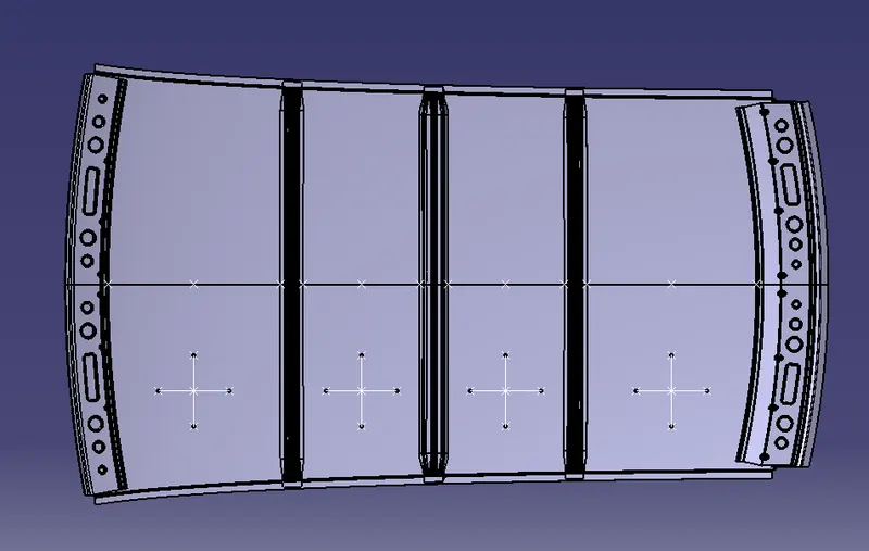
| Sl No. | Bow's | Rx | Ry | R | I | L | t | W | OK/NG |
| 1 | FR & 1st | 5707.009 | 2909.075 | 3853.75 | 486.836 | 1925 | 0.75 | 1.552 | OK |
| 2 | 1st & CTR | 4864.083 | 6632.11 | 5612.141 | 327.843 | 1925 | 0.75 | 1.787 | OK |
| 3 | CTR & 2nd | 4072.957 | 10100.83 | 5805.117 | 326.386 | 1925 | 0.75 | 1.84 | OK |
| 4 | 2nd & RR | 3348.906 | 14140.26 | 5415.283 | 476.562 | 1925 | 0.75 | 1.897 | OK |
Snow Load Criteria:
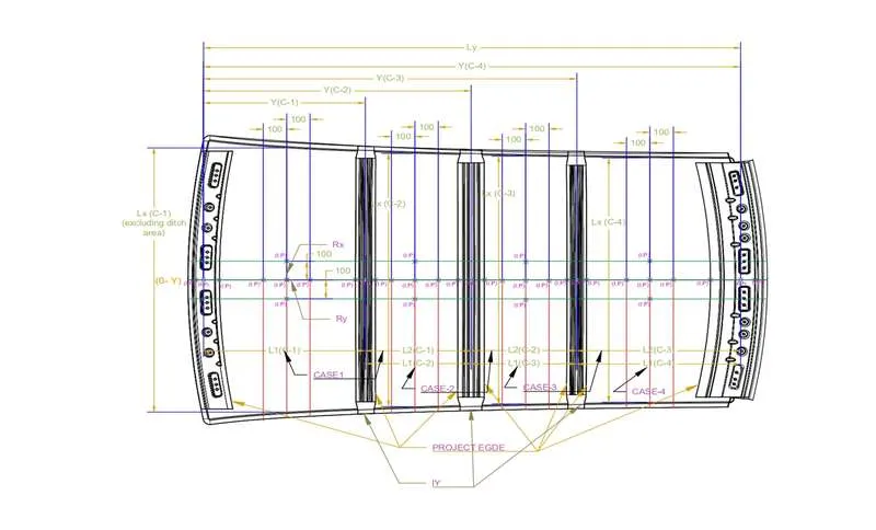
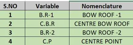
Prediction Formula:
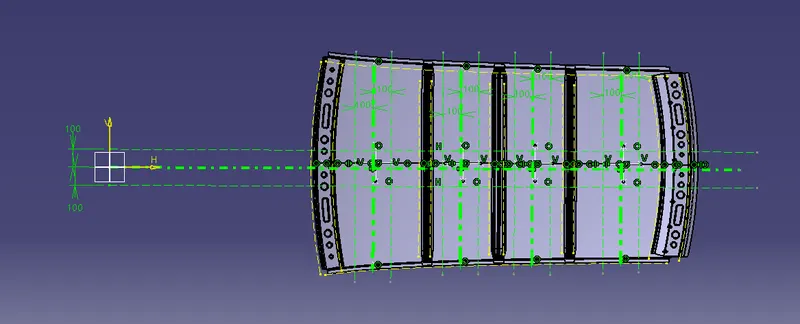
Qr = [Iy x t2] / [α x s x [(Rx + Ry)/2]2 x 10-8]
Where,
α = My x Lx2 x 10-12 , My = Y(Ly-Y)
t = Roof plate thickness [mm]
Ly = Distance between the front and rear roof Rails on the Vehicle along with 0Y[mm]
Length of Roof panel with the center point between Roof rail Front /Rear as the front and rear reference point.
Lx = Distance between the Left and Right end of the roof on the Roof BOW [mm]
The width of the roof panel is exposed on the surface.
Y = Distance from Front Roof Rail to Roof BOW[mm]
s = Distance for which Roof BOW bears divided load [mm]
s = L1/2 + L2/2
Iy = Geometrical moment of inertia of Roof BOW (Y cross-section )[mm4]
Rx = Lateral direction curvature radius of roof panel Y cross-section on Roof BOW [mm]
Roof panel curvature Radius of the Length Lx in Front view
Ry = Longitudinal Direction curvature radius of the Roof panel X cross-section on Roof BOW [mm]
Roof panel X curvature radius of length s in Side view
Judgment condition
Qr ≥ 3.1
250 ≤ s ≤ 380
From measuring the part we get,
Ly =1965.348 mm
t = 0.75 mm
CASE - 1
Lx =1134.349 mm
Y = 580.493 mm
L1 = 580.493 mm
L2 = 400.251 mm
Rx = 2633.133 mm
Ry = 2842.099 mm
Therefore,
s1 = 580.493/2 + 400.251/2 = 490.372 mm
My = 580.493(1965.348-580.493) = 803898.633 mm
α1 = 803898.633*1134.349^2*10^-12 = 1.034 mm
CASE - 2
Lx =1085.26 mm
Y = 400.251 mm
L1 = 400.251 mm
L2 = 398.849 mm
Rx = 3792.913 mm
Ry = 3316.011 mm
Therefore,
s2 = 400.251/2 + 398.849/2 = 399.55 mm
My = 400.251(1965.348-400.251) = 626431.6393 mm
α2 = 626431.6393*1085.26^2*10^-12 = 0.737 mm
CASE - 3
Lx =1063.123 mm
Y = 398.849 mm
L1 = 398.849 mm
L2 = 592.843 mm
Rx = 4222.648 mm
Ry = 4074.07 mm
Therefore,
s3 = 398.849/2 + 592.843/2 = 495.846 mm
My = 398.849(1965.348-398.849) = 624796.5597 mm
α3 = 624796.5597*1063.123^2*10^-12 = 0.706 mm
CASE - 4
Lx = 1046.913 mm
Y = 592.843 mm
L1 = 592.843 mm
L2 = 0 mm
Rx = 3792.913 mm
Ry = 3316.011 mm
Therefore,
s4 = 592.843/2 + 0 = 296.421 mm
My = 592.843(1965.348-592.843) = 813679.981 mm
α4 = 813679.981*1046.913^2*10^-12 = 0.891 mm
C.B.R
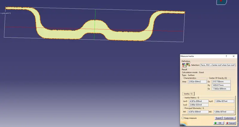
(Max Moment) M1 = 4.387e-009 m^4 = 4.387*10^3 mm^4
(Min Moment) M2 = 1.009e-007 m^4 = 1.009*10^3 mm^4
we only need is M1 as Iy,
B.R 1
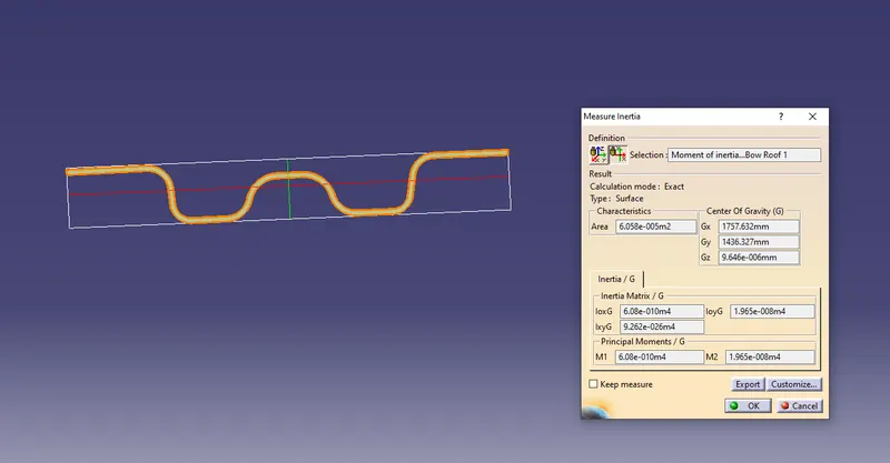
(Max Moment) M1 = 6.08e-010 m^4 = 6.08*10^3 mm^4
(Min Moment) M2 = 1.965e-008 m^4 = 1.965*10^3 mm^4
we only need is M1 as Iy,
B.R 2
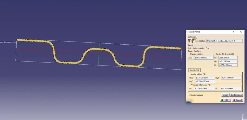
(Max Moment) M1 = 6.135e-010 m^4 = 6.135*10^3 mm^4
(Min Moment) M2 = 1.971e-008 m^4 = 1.971*10^3 mm^4
we only need is M1 as Iy,
| Sl No. | Bow's | Iy | a | Lx | Ly | Y | s | Rx | Ry | t | Qr | OK/NG |
| 1 | FR & 1st | 4387 | 1.034 | 1134.349 | 1965.348 | 580.493 | 490.372 | 2633.133 | 2842.099 | 0.75 | 64.938 | OK |
| 2 | 1st & CTR | 6080 | 0.737 | 1085.26 | 1965.348 | 400.251 | 399.55 | 3792.913 | 3316.011 | 0.75 | 91.92629 | OK |
| 3 | CTR & 2nd | 1971 | 0.706 | 1063.123 | 1965.348 | 398.849 | 495.846 | 4222.648 | 4074.07 | 0.75 | 18.40369 | OK |
| 4 | 2nd & RR | NA | 0.891 | 1046.913 | 1965.348 | 592.843 | 296.421 | 3792.913 | 3316.011 | 0.75 | #VALUE! | NA |
Conclusion:
While the design and manufacturing process of the roof, front roof rail, bow roof rails, central roof rail, and rear roof rail may vary depending on the specific vehicle model and manufacturer, it is true that the design typically involves considerations of master sections, moment of inertia, and draft analysis.
Master sections are a set of standard shapes that are used in the design of vehicle components, including roof rails. The use of master sections helps ensure that the components are designed to meet industry standards for strength, durability, and safety.
Moment of inertia is a measurement of the resistance of an object to rotational motion. It is an important factor in the design of roof rails, as it helps determine the strength and rigidity of the component.
Draft analysis involves the roof rails and simulate the manufacturing process. This helps identify any potential issues with the design or manufacturing process and ensures that the final product meets the desired specifications.
Overall, the design and manufacturing of roof rails and other components of the roof structure are crucial for ensuring the safety and performance of the vehicle. By following established design principles and using advanced manufacturing techniques, vehicle manufacturers can produce roofs that are strong, durable, and safe for passengers.