Week 9 - Attachment Feature Creation - Challenge 2
Attachment Feature Creation - Dog House
Aim: Design Dog House for the Door Trim by following the design rules, then perform draft analysis for Class-A surface. Create the final closed body component and perform draft analysis.
Description:
In order to create a final close body component for a door trim, the following steps should be taken:
- Create the tooling axis to ensure proper part release during the molding process.
- Design the Class-B and Class-C surfaces and join them to create a unified surface.
- Use the Close Surface feature to convert the surface into a solid body.
- Design the required dog house for the door trim, considering the design rules and performing draft analysis.
- Perform draft analysis for the final component to ensure easy part release and avoid molding defects.
- Class A surface
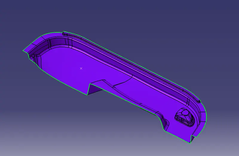
- Tooling axis creation: The Tooling Direction refers to the direction in which the mold extracts the part. Typically, the mold is constructed in two separate pieces: the Cavity and Core sides. The Core moves away from the Cavity, creating the Dye line, which also serves as the Tooling Direction.
Steps to create top tooling axis:
- Extract the flat element of class A surface and untrimmed it.
- Create a center point at 0 mm on the base surface.
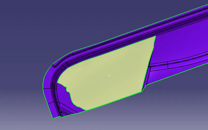
- Create a line perpendicular to the surface; which will be our top tooling axis.
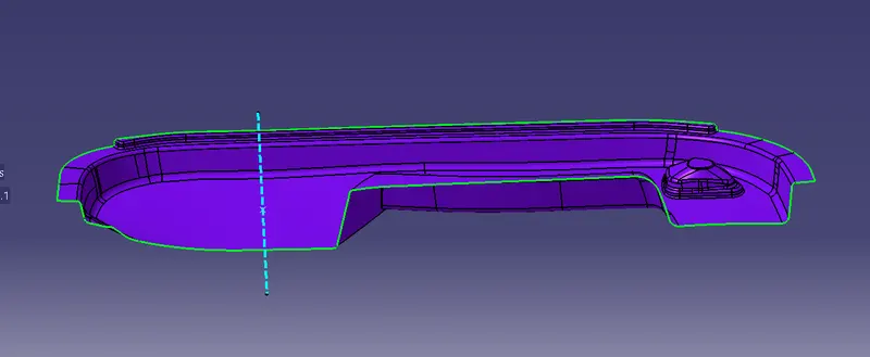
- Draft analysis: Draft analysis is used to determine whether a part can be easily extracted. This analysis involves identifying color ranges on the analyzed element, representing areas where the deviation from the draft direction at any point corresponds to specific values. This enables you to detect whether the drafted part can be removed without difficulty.
Steps for draft analysis:
- Go to the "Insert" tab.
- Hover on the analysis, and click on "Feature Draft Analysis".
- Click on the compass icon.
- Align the compass with the tooling axis.
- Click on the surface to obtain the result.
- Result will be shown in different colors.
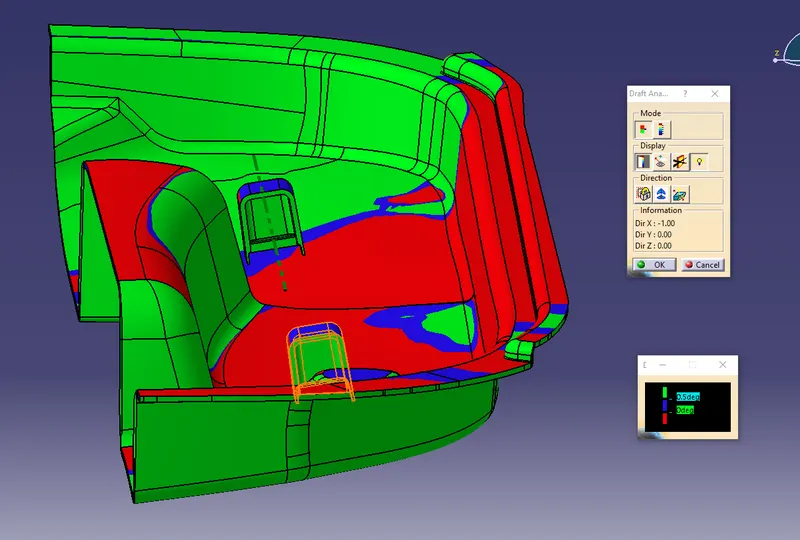
- In my case, Green is the tooling faces that have more than 0.5 degrees draft angles and Blue is the faces with a draft angle of at range of 0-0.5 degrees.
Class A surface:
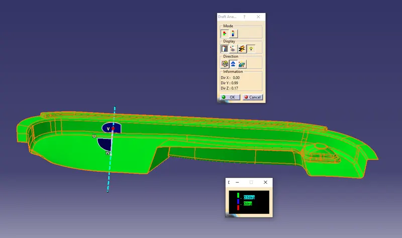
Note: In the draft analysis, the Class A surface had few elements with a draft angle of less the 0.5 degrees. I tried with different tooling axes and took help from dought clearing sections, but the answer was Class A surface has an error.
Full part without the dog house:
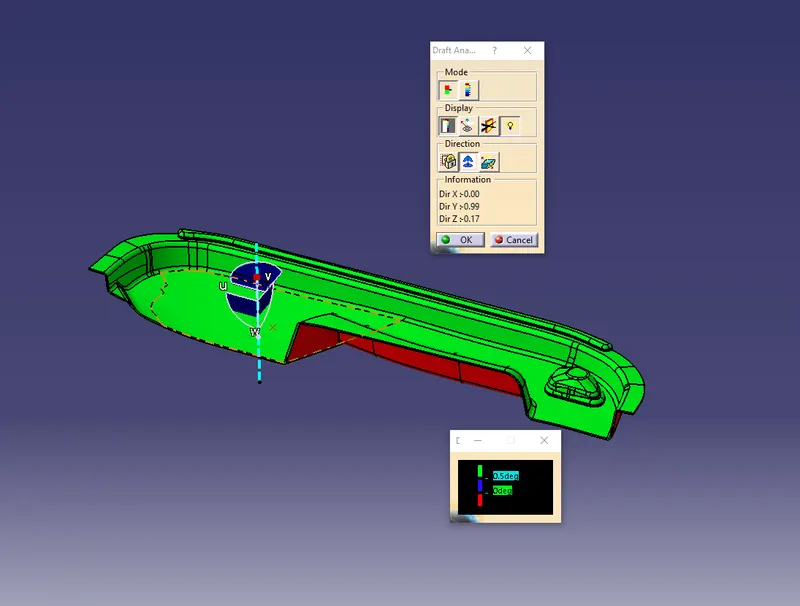
- Dog house creation: The dog house is a design feature utilized in plastic trim engineering that serves as a supporting element. In some cases, additional engineering features such as snaps and locators are mounted on them to enhance their durability. These features, including the dog house, are created on the B-surface.
Design rules for Dog house creation -
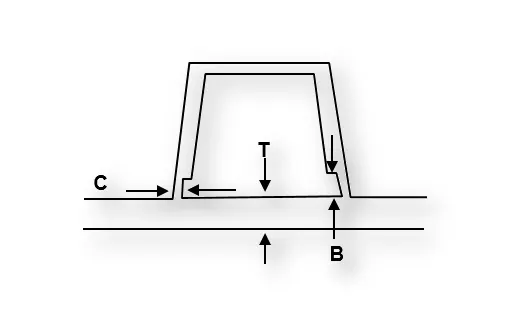
"C" is where the doghouse contacts the backside of the surface
-
Doghouse wall thickness at the intersection of the part wall ( C ) should be 40% or less than the main wall stock ( T ).
-
The height of ( B ) should be between 3.0 – 6.0 mm
To design a dog house while considering the design rules:
- First extract the surface on which the dog house will be created. Then, create a sketch on a plane tangent to the surface.
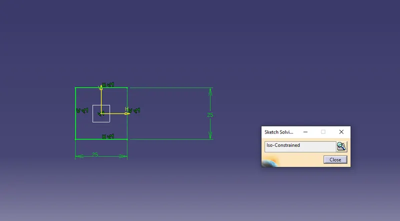
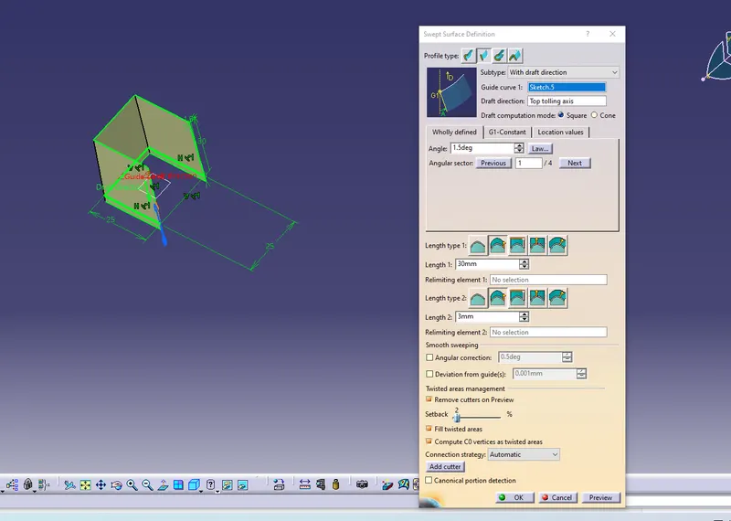
- Using sweep feature, the sketch was swept with draft direction at a 1.5-degree angle inward with a hight of 30 mm.
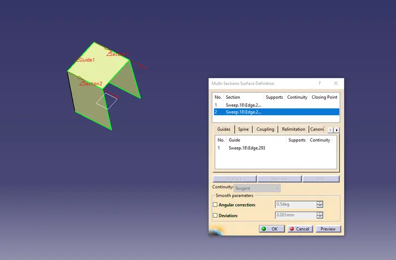
- Now we have closed the upper surface of the dog house by using multisection and join it together.
- A thickness of 2.5 mm has given to the surface by using a thick surface feature in Part design.
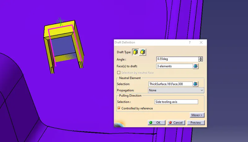
- A draft of 0.55 degrees is provided to the inner surface of the dog housekeeping one face as neutral and pulling direction is the Side tooling axis.
- Now I created a copy of the dog house body and trimmed it with an offset surface of extrude of the class b surface.
- Then using Boolien operation to remover it from the dog house and filleted all the surface according to the rules.
- Hence, dog house was created.
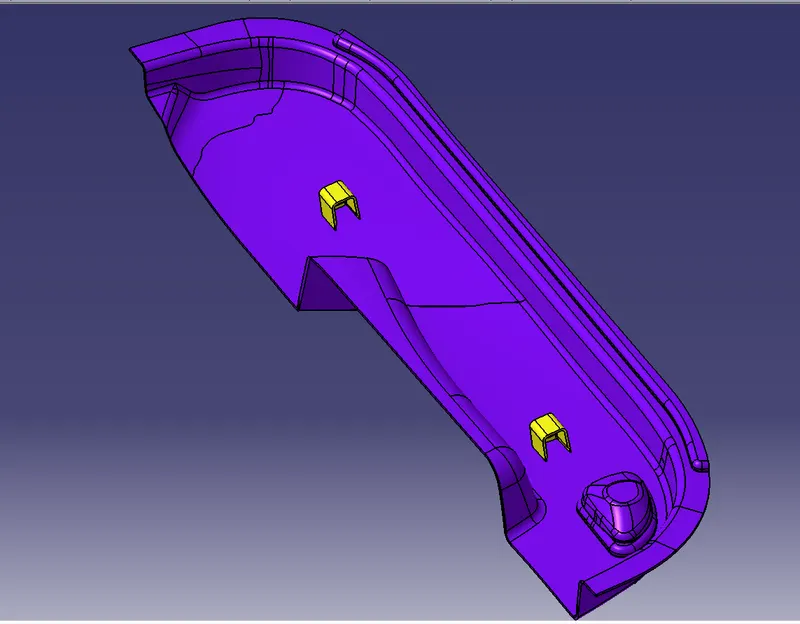
- After this, I created a copy of the completed dog house and rename it 2nd dog house and translated it to the next point created.
- Side tooling axis:
Steps to created side tooling axis-
- Create a pint on the surface of the neutral face of the dog house.
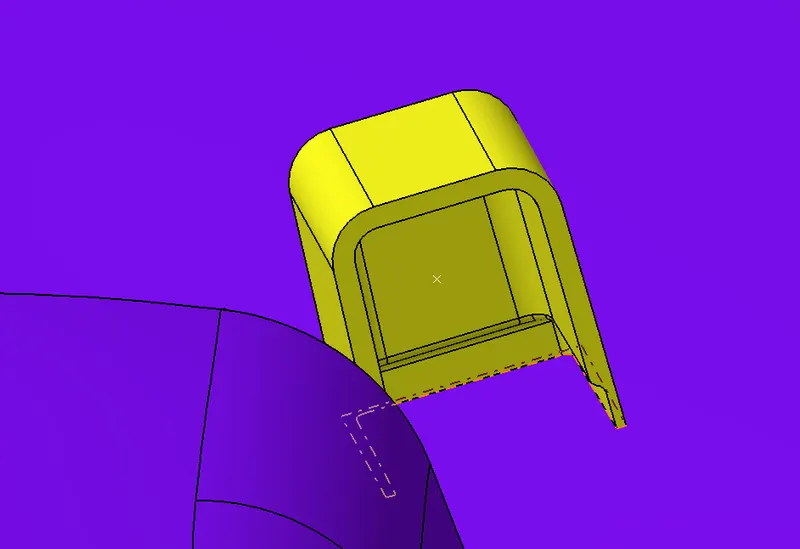
- Created a line perpendicular to the surface.
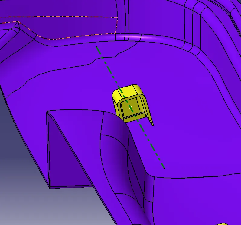
- Draft analysis with the dog house:
Isometric, Front, Side, and Top View: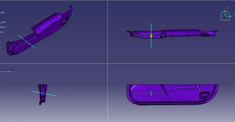
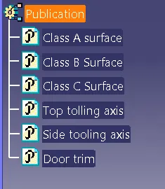
Publications: