Week 8 - Challenge 6 - Core & Cavity Design
Core & Cavity Design
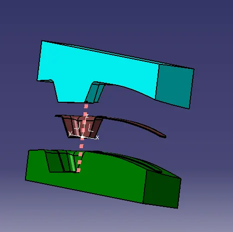
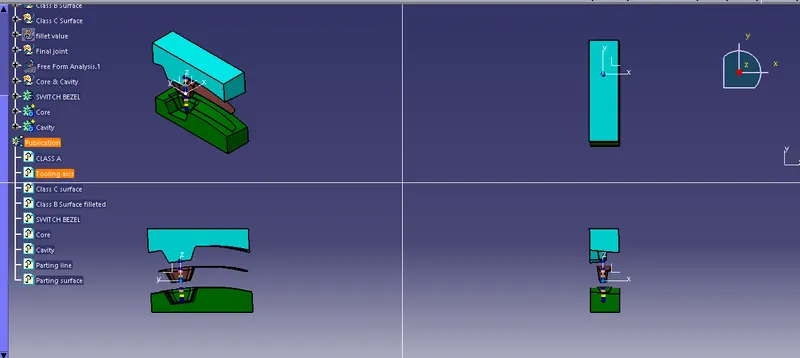
Objective: To generate the Core and Cavity blocks for the switch bezel component.
Description:
- Tooling Axis : The Tooling Direction refers to the direction in which the mold extracts the part. Typically, the mold is constructed in two separate pieces: the Cavity and Core sides. The Core moves away from the Cavity, resulting in the creation of the Dye line, which also serves as the Tooling Direction.
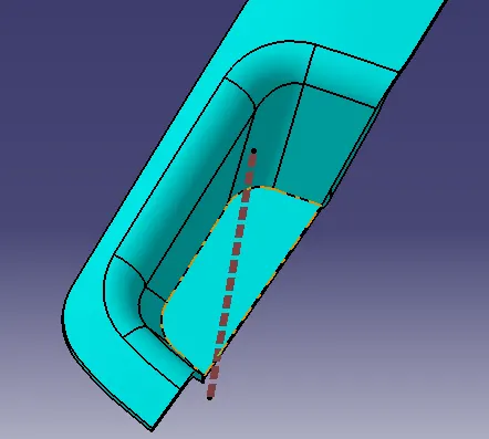
Steps to create tooling axis:
- Extract the class A surface.
- Create a center point at 0 mm on the base surface.
- Generate an axis system at that point.
- Switch the model view to the X direction.
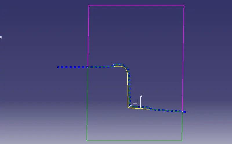
- Use the “intersect” in the ZY plane to obtain the boundary lines.
- Create lines along the slant surfaces in the sketch.
- Using the "bisecting line" feature, select the two lines to obtain the temporary tooling axis for the X-direction view.
- Switch to the Y direction view and intersect the switch Bezel part in the ZX direction to obtain intersecting lines.
- Draw a line in sketch mode using the axis center point and constrain it at a 3-degree angle.
- Finally, bisect both lines to obtain the final tooling axis.
- The resulting line represents the tooling axis for the surface.
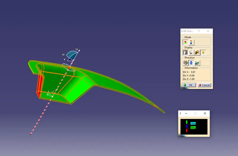
- Draft analysis: Draft analysis is used to determine whether a part can be easily extracted. This analysis involves identifying color ranges on the element being analyzed, which represent areas where the deviation from the draft direction at any point corresponds to specific values. This enables you to detect whether the drafted part can be removed without difficulty.
Steps for draft analysis of the part:
- Go to the "Insert" tab.
- Hover on the analysis, and click on "Feature Draft Analysis".
- Click on the compass icon.
- Align the compass with the tooling axis.
- Click on the surface to obtain the result.
- Result will be shown in different colors.
- In my case, Green is the tooling faces that have more than 2 degrees draft angles and Red is the faces with a draft angle of less than 0 degrees.
- Parting Surface & line:
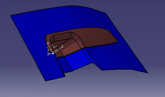
Parting surface: Injection molds typically consist of two major components: the movable halves and the fixed halves. During the injection molding process, these halves are pressed tightly together to form a sealed hollow, preventing any melt flow leakage and maintaining a specific holding pressure. The surface where the halves are pressed together is known as the parting surface, which is usually the largest projected outline surface of the part. The design of the parting surface directly impacts the quality of the product, as well as the ease of constructing and operating the injection mold.
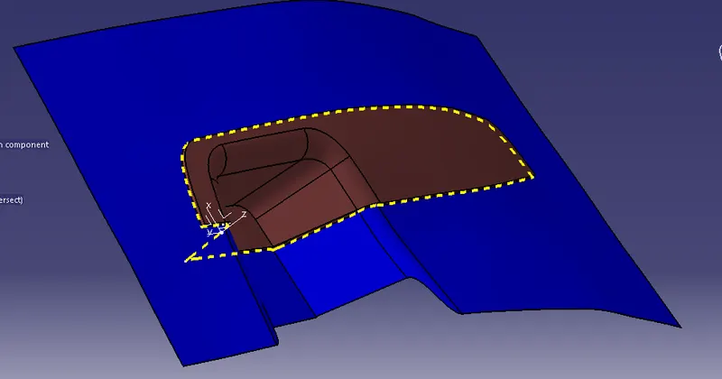
Parting line: The parting line is the location where the two halves of the mold meet, creating a visible and noticeable physical line on the part. However, these lines can be hidden or minimized by placing them along the edges of the part. In the picture below, the dotted Yellow line represents the parting line.
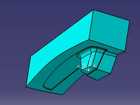
- Core design: Steps included for core design:
- Extrapolate class A surface
- Trim the extrapolated class A surface with class C to get inside part of the core.
- To create the parting surface, I used the trimmed surface of extrapolated surface & Class C surface and trimmed them.
-
Next, using the sketch function a rectangular box is drawn and extruded over the parting surface.
- Fill function is used to close the open area and from part design, closed surface is used to make the core solid.
- Cavity Design: Steps included for cavity design:
- Using the sketch for the rectangle earlier, we extrude another box that is in opposition to the core part and trim it with the parting surface.
- Fill function is used to close the open area and from part design, closed surface is used to make the cavity solid.
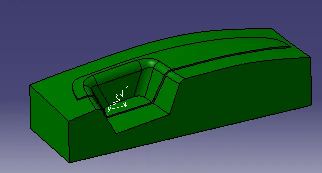
- Core, Cavity and Part