Development of a Door Trim panel
Report on Final Project
Aim: To create a CAD model considering following inputs as like in OEM and tier1 companies
a) Class A surface
b) Nominal thickness : Refer master sections
c) Attachment strategy : Find a attachment strategy for the door panel complete work. Use Push pin with Dog house for Lower substrate - Door panel attachment. Use heat stakes for part to part attachment
Discription:
Door trims are an integral part of the interior design of a vehicle, and they typically contain most of the controls and decorative components that are essential for the convenience and comfort of the driver and passengers. The door trim consists of several components such as the armrest, map pocket, switch bezel, speaker, and various electronic regulators, and aesthetic trims that are designed to improve the overall user experience.
The plastic trim is attached to the sheet metal component, which is the door inner, with the help of various engineering features. These engineering features include push clips, which snap into pre-drilled holes in the sheet metal, and heat stakes, which are melted into the sheet metal to secure the plastic trim. These features ensure that the plastic trim is securely fastened to the door inner, providing a durable and long-lasting solution for the door trim component.
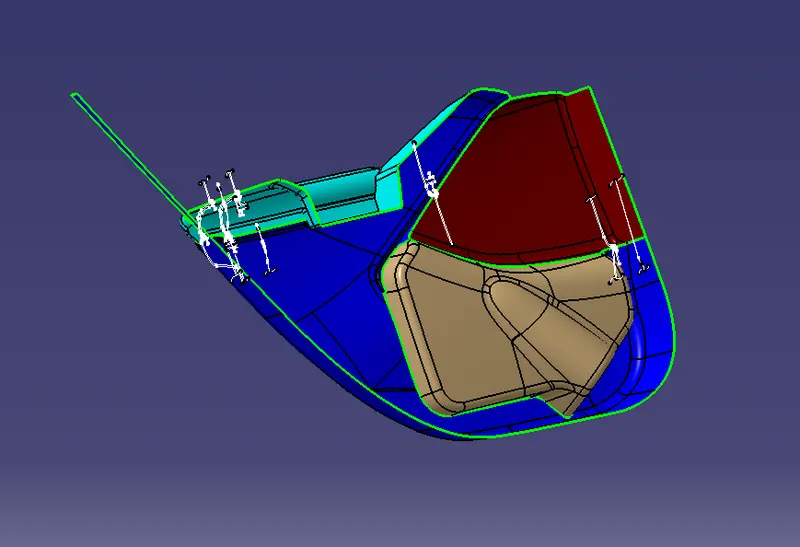
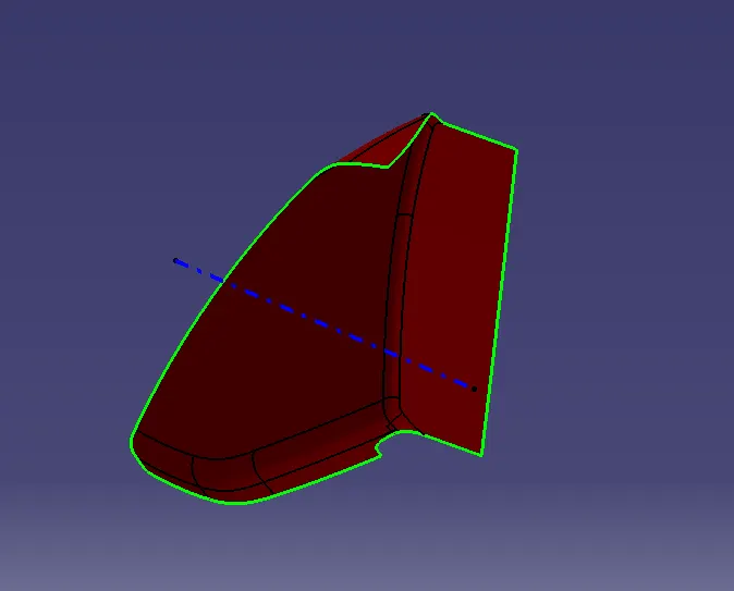
Tooling Axis Creation: The Tooling Direction refers to the direction in which the mold extracts the part. Typically, the mold is constructed in two separate pieces: the Cavity and Core sides. The Core moves away from the Cavity, creating the Dye line, which also serves as the Tooling Direction.
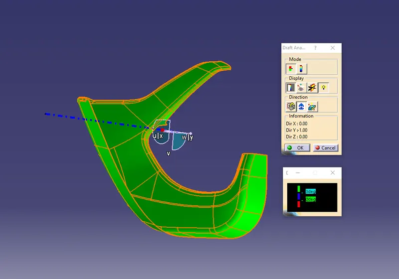
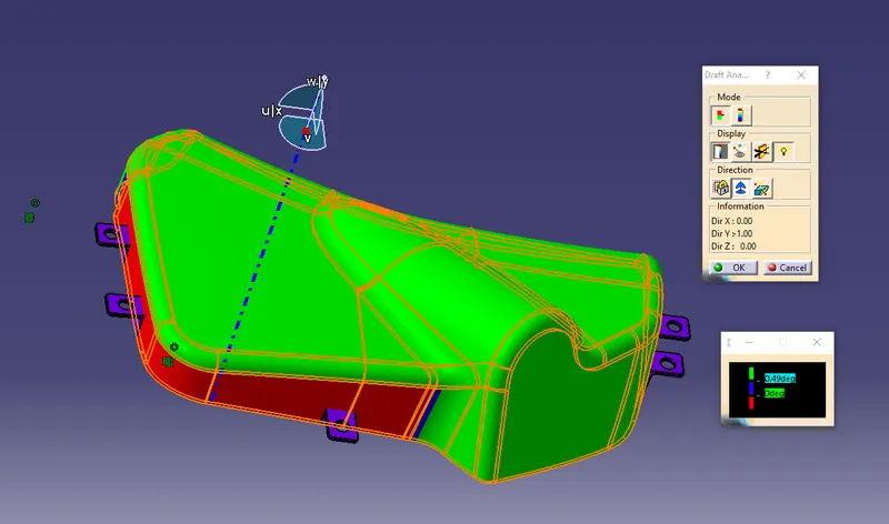
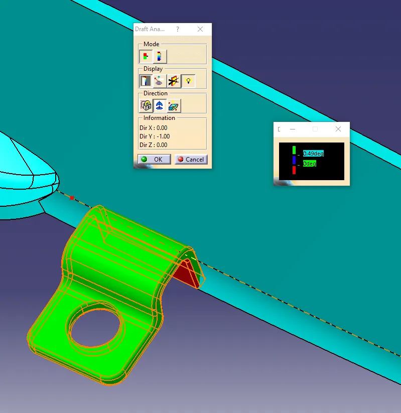
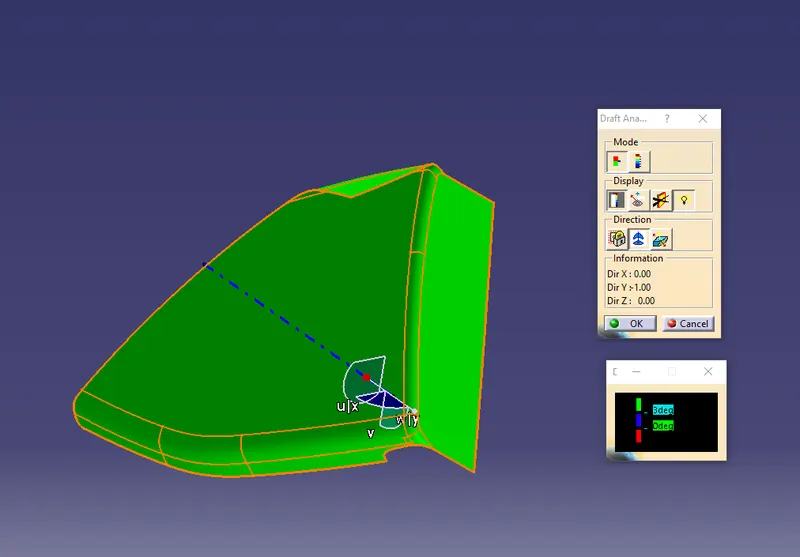
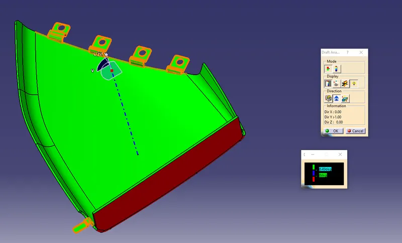
Draft Analysis: Draft analysis is used to determine whether a part can be easily extracted. This analysis involves identifying color ranges on the analyzed element, representing areas where the deviation from the draft direction at any point corresponds to specific values. This enables you to detect whether the drafted part can be removed without difficulty.
In product design and manufacturing, Class A Surface, Class B Surface, and Class C Surface are commonly used terms to describe different types of surfaces used in the creation of CAD models.
Class A Surface refers to the exterior surface of a product, which is visible to the customer and has an important role in defining the aesthetics of the product. Class A surfaces need to be free of any visible defects, such as scratches, bumps, or waviness.
Class B Surface is the surface that is created by offsetting the Class A surface by a specific distance or thickness. This surface is used to define the interior or underside of the product and is generally less critical than the Class A Surface in terms of aesthetics.
Class C Surface is the surface that connects the Class A and Class B surfaces. It is typically used to define the thickness of the product and to provide structural support.
Together, Class A, B, and C Surfaces make up the shell of a product and are essential for creating a CAD model that accurately represents the design intent of the product. The design and engineering of these surfaces require a high level of skill and attention to detail to ensure that the final product is both aesthetically pleasing and functionally sound.
Locators: They are small protrusions or depressions on the surface of the component that are used to ensure accurate positioning of other components during assembly. They can be used to ensure that a part is aligned in the correct position and held securely in place. Locators are often designed with a specific shape and size to match the corresponding part.
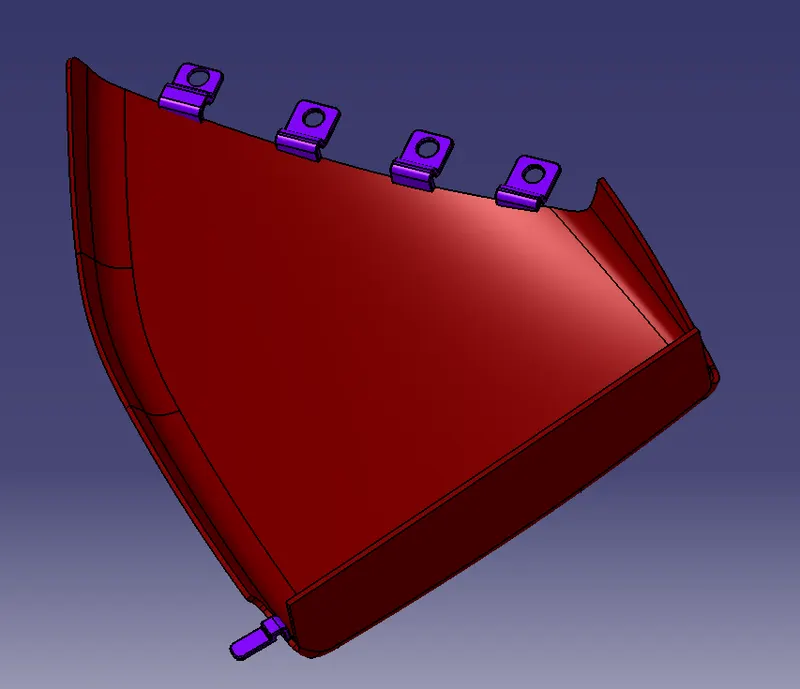
Heat Stakes: They are small protrusions on a plastic component that are melted or deformed during the assembly process to create a mechanical bond with another component. They are often used as an alternative to fasteners or adhesives, and are commonly found in automotive and electronic applications where high volume production is required. Heat stakes can be designed in various shapes and sizes to suit different assembly requirements, and are typically made of the same material as the plastic component. The process of creating heat stakes involves using a heated tool to melt or deform the plastic at specific locations on the component, which then solidifies and creates a secure bond with another component.
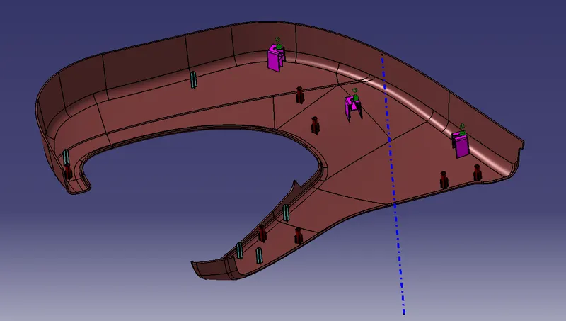
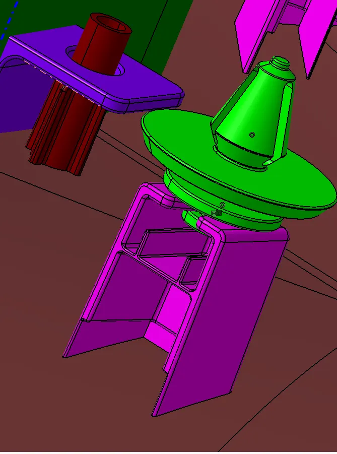
Dog House: It is an engineering feature used in plastic trim design to provide support and improve the strength of the component. It is usually built on the B-surface of the component and can serve multiple functions such as lifting bosses for height, creating outside bosses from the B-surface, and eliminating sink marks. The design of a dog house involves careful consideration of design rules such as draft angles, fillets, and other features to ensure the component meets required strength and aesthetic standards.
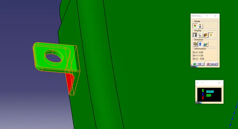
Flanges: They are raised areas on the surface of a component that are used to provide additional strength and stiffness. They are often used in conjunction with screws, bolts, heat stakes,locators or other fasteners to securely attach the component to another surface. Flanges can be designed in a variety of shapes and sizes to suit the specific requirements of the application.
Push pins/Clips: They are a common type of fastener used in automotive design to attach plastic trim components to metal substrates. They are typically made of plastic and feature a ribbed shaft with a flared end that allows for easy installation and secure retention. Push clips are commonly used to attach interior trim pieces such as door panels, dashboard components, and headliners to the metal frame of the vehicle. They provide a secure attachment while also allowing for easy removal for service or repair. Push clips are often preferred over traditional mechanical fasteners such as screws or bolts as they are faster and easier to install, reducing manufacturing time and cost.
Designing:
- Lower substrate:
Tooing axis Creation:
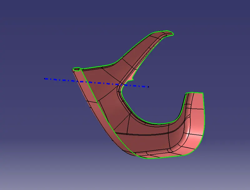
Final Part
Draft analysis:
Class A Surface:
Final Part:
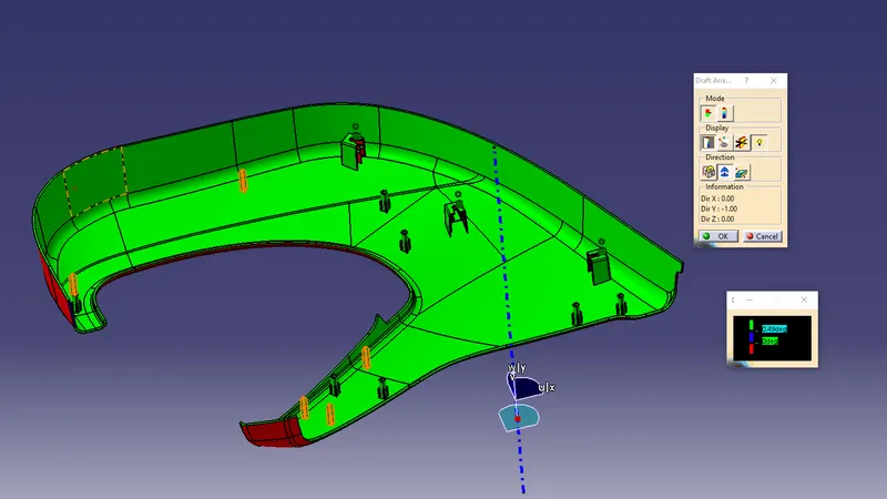
Dog house using side core axis:
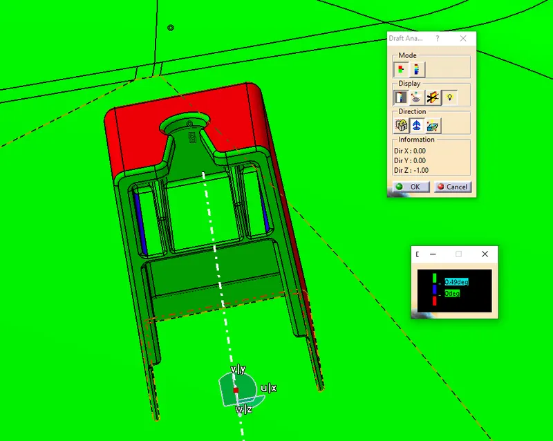
Heat Stakes:
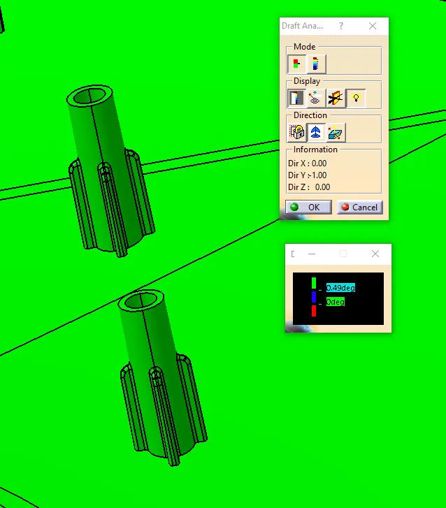
Locators:
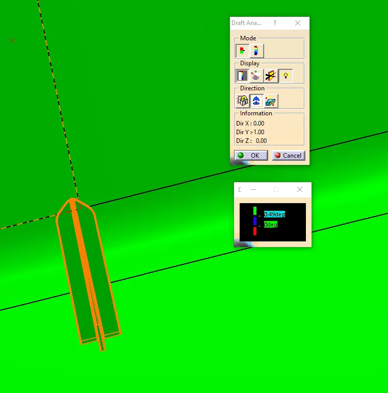
- Bottle Holder
Tooling axis:
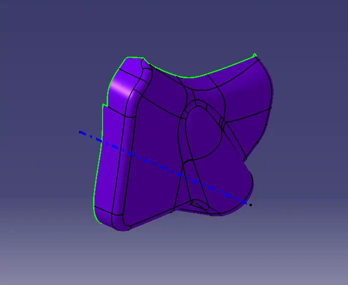
Final Part:
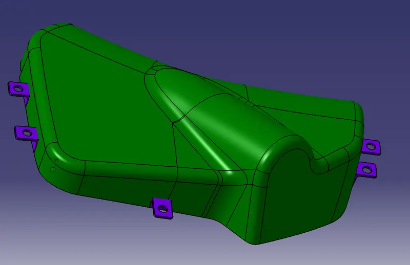
Draft analysis:
Class A Surface:
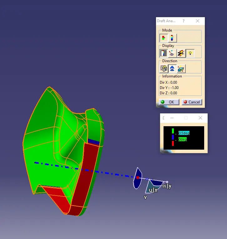
Note: This class A surface is not proper, which have a few 0 degree drafts.
Final Part:
Flanges:
- Arm rest:
Tooling axis:
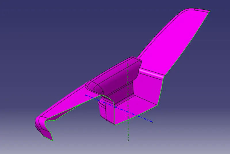
Main tooling axis, Side tooling axis
Draft analysis of Class A Surface using Side tooling axis:
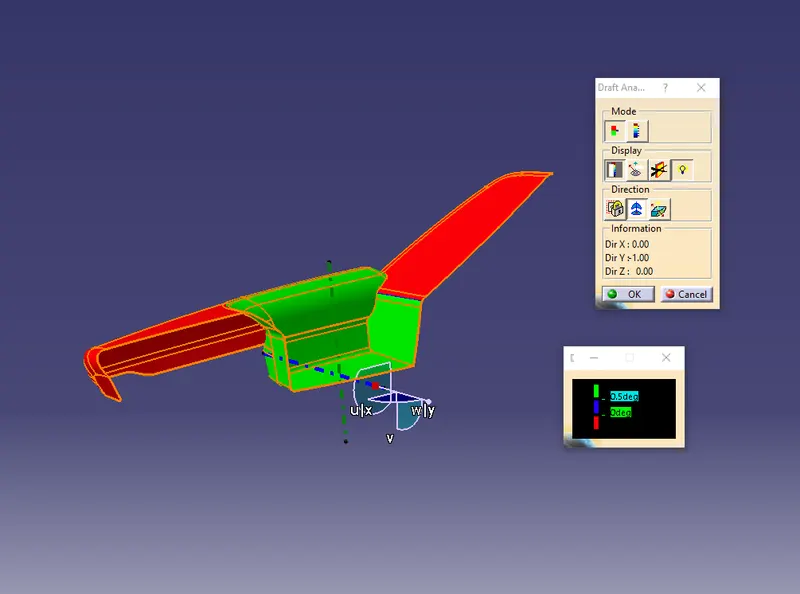
Draft analysis of Class A Surface using Main tooling axis:
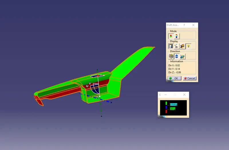
Note: This class A surface has many surface which are less the 0 degree so it cannot be machined using one tooling axis. therefore, i have use two tooling axis.
Final Part:
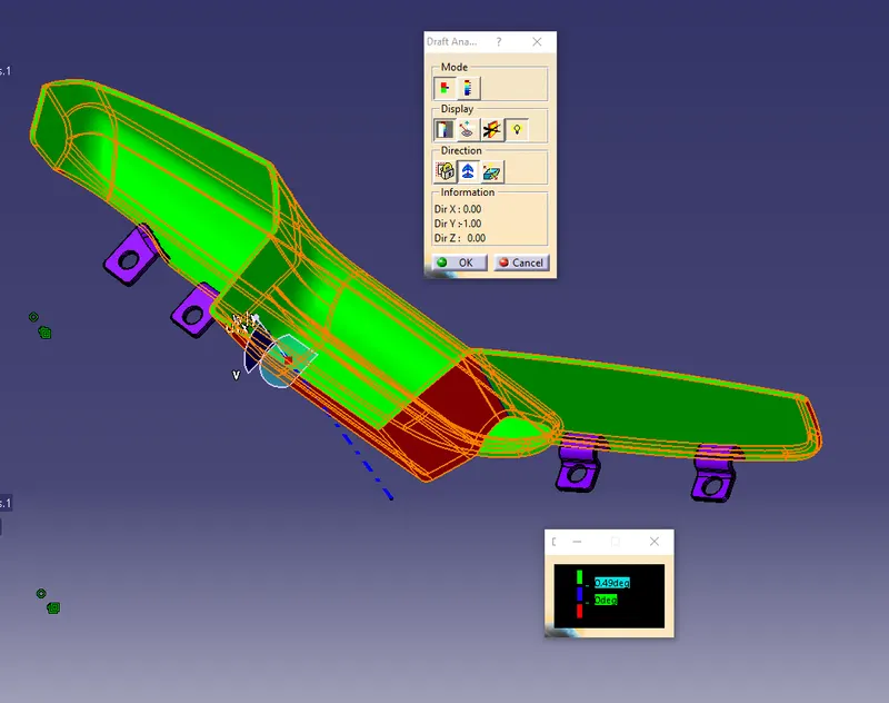
Note: I have applied assamble boolion operation to the flanges in the Arm rest but it is still not incuded in the draft analysis, i have tryied changing it to Add boolion operation but its the same.
Flanges:
- Map Pocket
Tooling axis:
Final Part
Draft analysis:
Class A Surface:
Final Part:
- Push pin/clip:
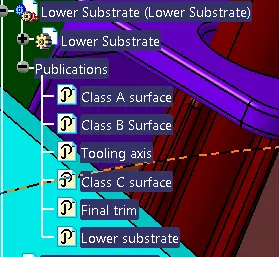
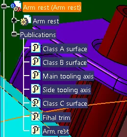
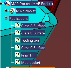
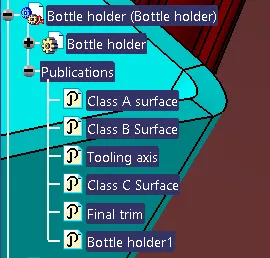
Publications:
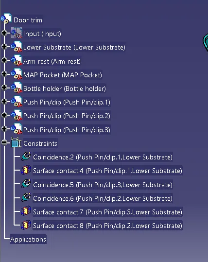
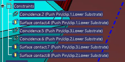
Constraints:
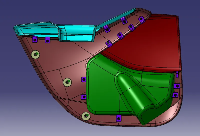
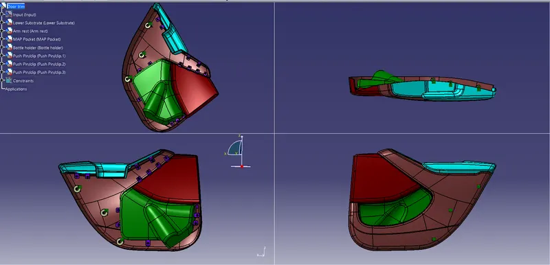
Final Assambly: