Week 9 - Project_1 - Door Trim Lower with Engineering Features
Project: Door Trim Lower with Engineering Features
Aim: To create Door Trim Lower Plastic component through the given Class-A surface. To begin with, the tooling axis for the given Class-A Surface should be created meeting the requirements of the draft angle and at the end perform the Draft analysis on the model.
Also to create Heat Stakes and the locators considering the design rules mentioned in the video for the door applique.
Description:
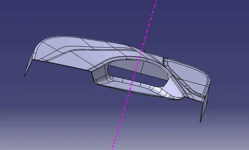
Tooling Axis Creation: The Tooling Direction refers to the direction in which the mold extracts the part. Typically, the mold is constructed in two separate pieces: the Cavity and Core sides. The Core moves away from the Cavity, creating the Dye line, which also serves as the Tooling Direction.
Steps to create top tooling axis:
- Select an axis from which most of the surface is vsible then extract an element of class A surface.
- Create a center point at 0 mm on the base surface.
- Create a line perpendicular to the surface; which will be our tooling axis.
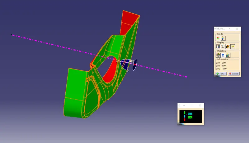
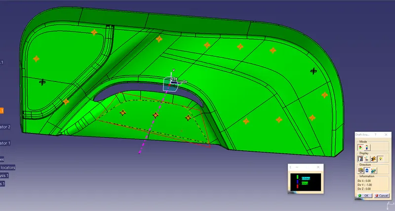
Draft Analysis: Draft analysis is used to determine whether a part can be easily extracted. This analysis involves identifying color ranges on the analyzed element, representing areas where the deviation from the draft direction at any point corresponds to specific values. This enables you to detect whether the drafted part can be removed without difficulty.
Steps for draft analysis:
- Go to the "Insert" tab.
- Hover on the analysis, and click on "Feature Draft Analysis".
- Click on the compass icon.
- Align the compass with the tooling axis.
- Click on the surface to obtain the result.
- Result will be shown in different colors.
- In my case, Green is the tooling faces that have more than 3 degrees draft angles.
Class A surface: This surface is considered an aesthetic surface as it is visible to customers, specifically the top surface.
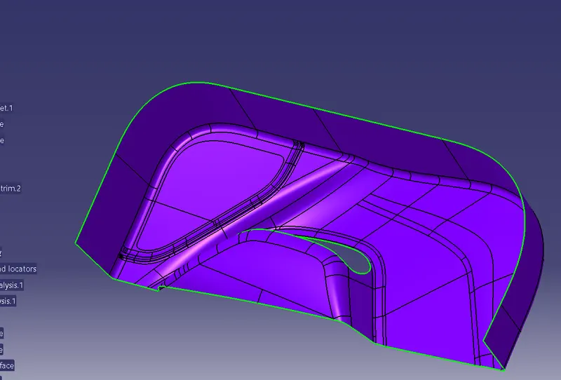
- Tooling Axis:
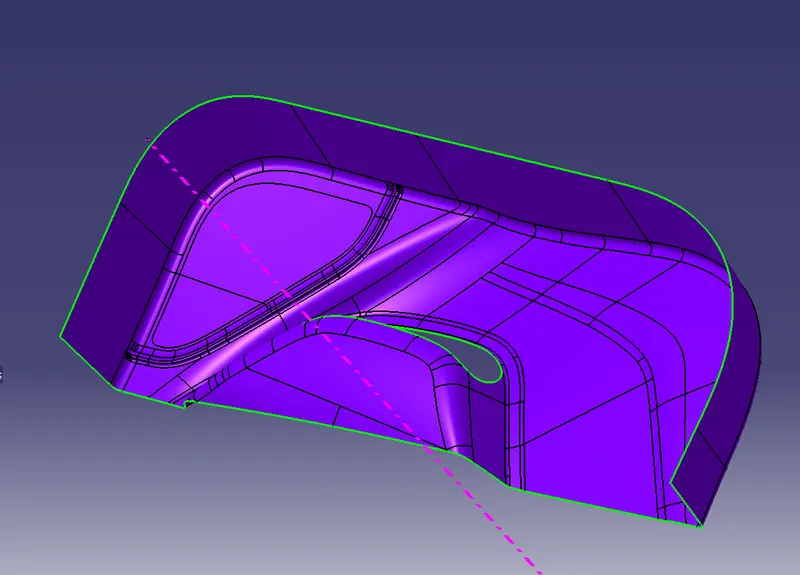
- Draft Analysis of Class A Surface:
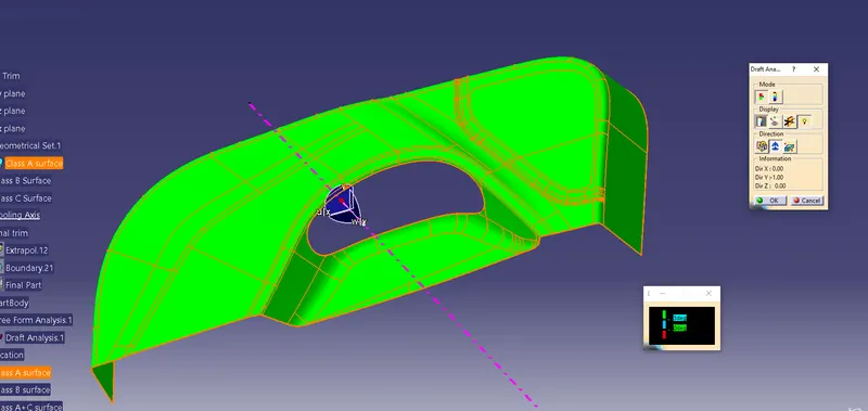
Final Part: This part is the combination of three surface- Class A, Class B & Class C surface.
- Draft Analysis of the part without Heat Stakes and the locators:
Part with Heat Stakes and the locators:
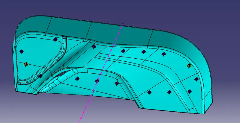
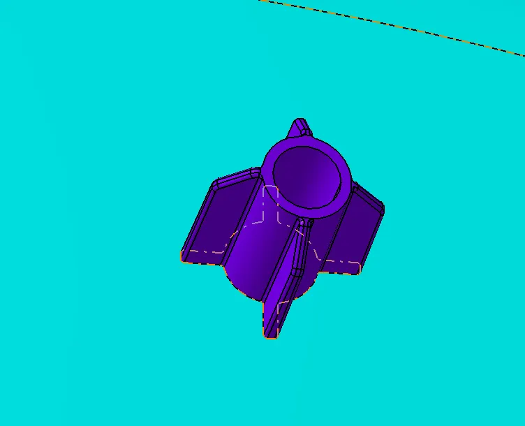
Locators: I created a geometric set and drew a sketch with reference to a plane and projection point. Then, I used the PAD command to create a solid object based on the sketch, with a specified thickness of 1.25 and a neutral element. To ensure proper release of the part from the mold, I added a draft of 0.55 degrees and applied a fillet on the locators side.
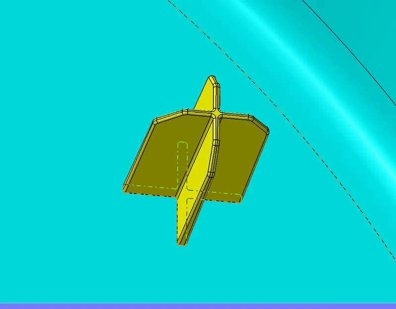
Heat Stakes: I created a geometric set and drew a sketch by referencing a plane and projection point. Then, I used the PAD feature to create a solid body within the specified dimension limits and with a neutral element. To ensure ease of removal during the molding process, I added a draft angle of 0.55 and added a fillet on the locator side.
Draft Analysis of the final part:
Here, Green is the tooling faces that have more than 0.5 degrees draft angles.
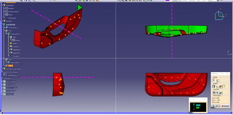
Isometric, Front, Side, and Top View:
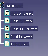
Publications: