Week 9 - Attachment Feature Creation (Ribs & Screw Boss) - Challenge 1
Attachment Feature Creation (Ribs & Screw Boss)
Aim: Using the given Class-A surface, generate the component while ensuring that the tooling axis meets the required draft angle. After creating the component, conduct a Draft analysis to ensure that the draft angle is appropriate. Design the rib and screw boss in accordance with the relevant design rules.
Description:
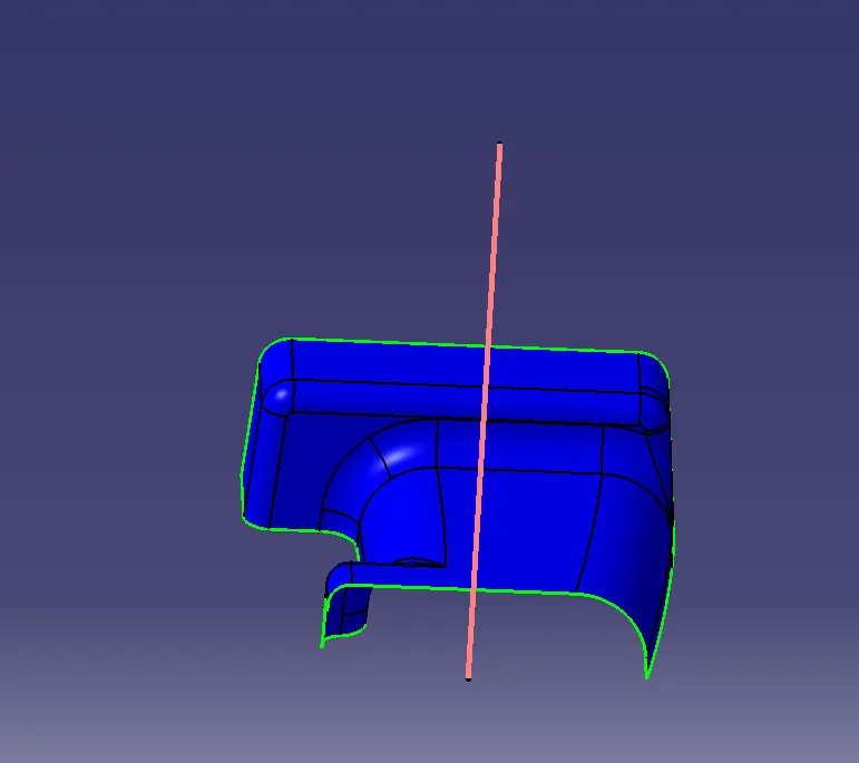
- Tooling axis Creation: The Tooling Direction refers to the direction in which the mold extracts the part. Typically, the mold is constructed in two separate pieces: the Cavity and Core sides. The Core moves away from the Cavity, creating the Dye line, which also serves as the Tooling Direction.
Steps to create tooling axis:
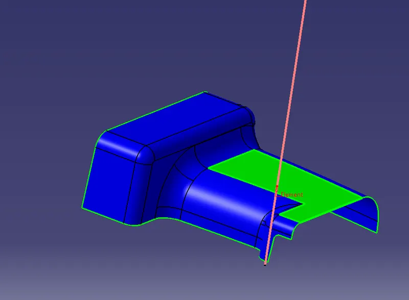
- Extract the flat element of class A surface and untrimmed it.
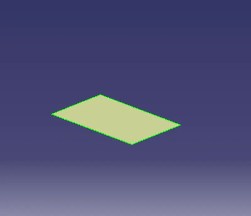
- Create a center point at 0 mm on the base surface.
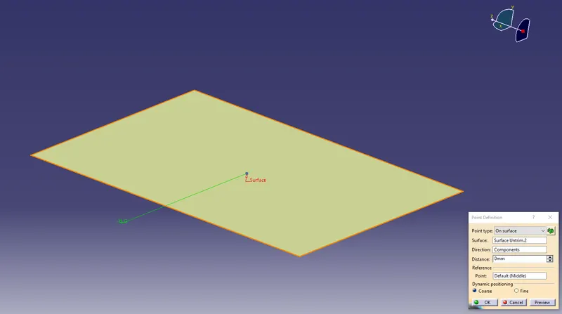
- Make two lines and bisect them to form the axis at that point using the bisect function in "line definition".
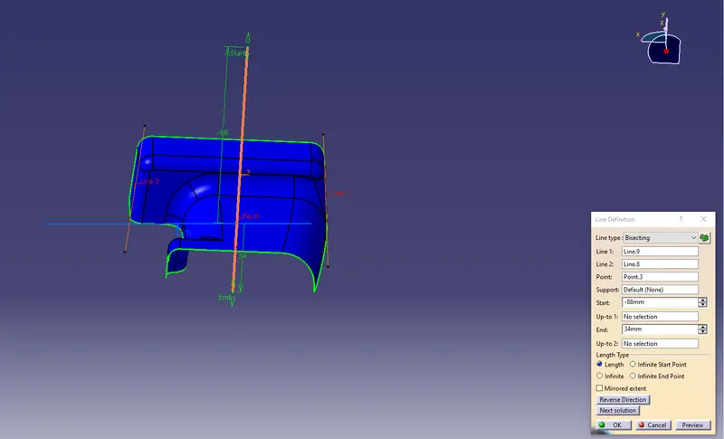
- The resulting line represents the tooling axis for the surface.
- Draft analysis of Class A surface: Draft analysis is used to determine whether a part can be easily extracted. This analysis involves identifying color ranges on the analyzed element, representing areas where the deviation from the draft direction at any point corresponds to specific values. This enables you to detect whether the drafted part can be removed without difficulty.
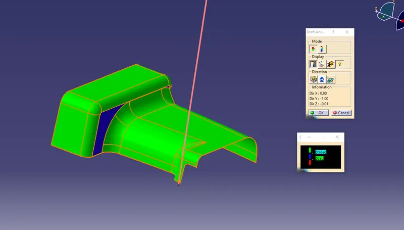
Note: In the draft analysis, the Class A surface had few elements with a draft angle of less the 0.5 degrees. I tried with different tooling axes and took help from dought clearing sections, but the answer was Class A surface has an error.
Steps for draft analysis:
- Go to the "Insert" tab.
- Hover on the analysis, and click on "Feature Draft Analysis".
- Click on the compass icon.
- Align the compass with the tooling axis.
- Click on the surface to obtain the result.
- Result will be shown in different colors.
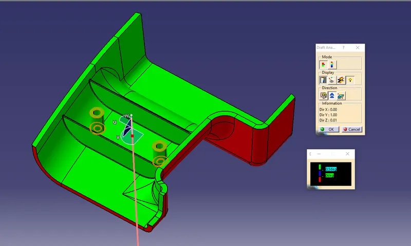
- In my case, Green is the tooling faces that have more than 0.5 degrees draft angles and Blue is the faces with a draft angle of at range of 0-0.5 degrees.
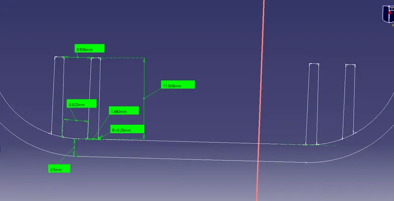
Ribs and screw boss creation in the part
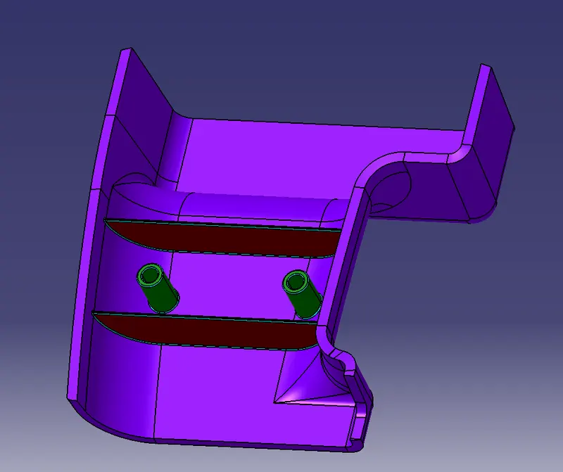
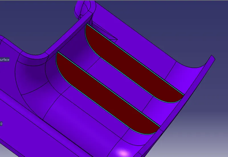
- Ribs :
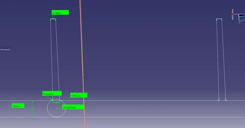
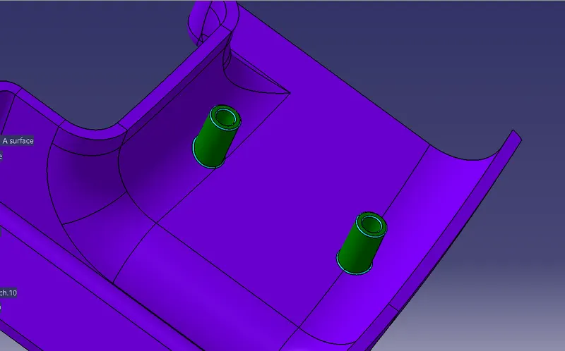
- Screw Boss:
Draft analysis of the part:
Steps for draft analysis of the part:
- Go to the "Insert" tab.
- Hover on the analysis, and click on "Feature Draft Analysis".
- Click on the compass icon.
- Align the compass with the tooling axis.
- Click on the surface to obtain the result.
- Result will be shown in different colors.
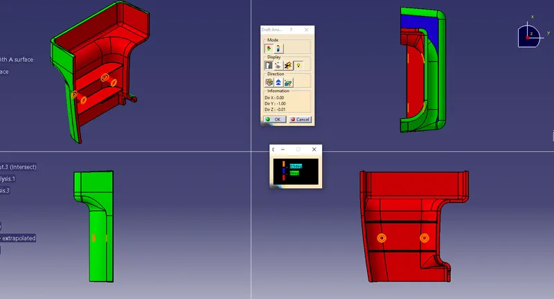
- In my case, Green is the tooling faces that have more than 0.5 degrees draft angles, Blue is the faces with a draft angle of a range of 0-0.5 degrees and Red is the faces with a draft angle of less than 0 degrees.