Roof challenge
ROOF DESIGN:
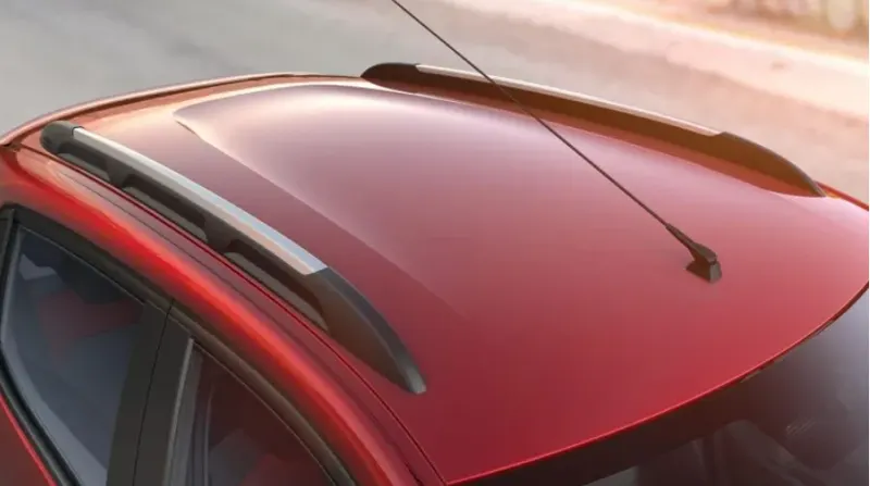
OBJECTIVE:
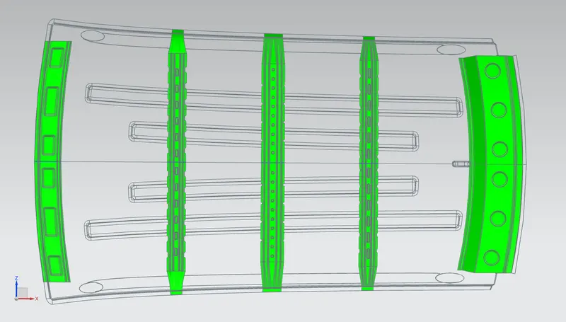
- The objective of this project is to design car roof with essential ROOFSFlanges and Reinforcements like ditch area,Front roof rail, Bow roofs, central roof rail and rear roof rail for the given styling surface.
- Perform a curvature study on the roof and perform the calculations for the heat distortion and snow load criteria to determine whether the bow roofs are at the correct positions.
- Finding moment of inertia for bow roofs, central roof rail, front rail and rear roof rail.
- Perform the draft analysis for each reinforcements.
INTRODUCTION:
The roof of car or other vehicle is the top part of it which protects passengers or goods from the weather, The roof also protects the Passengers from any injury when the car gets crashed or is rolled over or something heavy falls on the roof, also it protects passengers from Sun, wind, rain, and other external elements, Roof is attached to front and back roof rail.
REINFORCEMENTS:
If the roof is flat it is very weak and cannot able to with stand the forces like snow, so in order to increase the strength of the roof these reinforcements like front roof rail, central roof rail, rear rail and the bow roofs are introduced and joined to the flat surface of the roof with the different joining process.
Different Types of reinforcements that the car has are:
- Front roof rail
- Bow roofs
- Central roof rail
- Rear roof rail
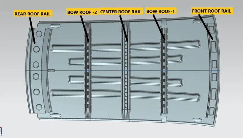
DESIGN CONSIDERATION:
- Visibility criteria
- Head clearance
- Curvature study
- Heat distortion and snow load criteria
- Draft analysis\
FRONT ROOF RAIL:
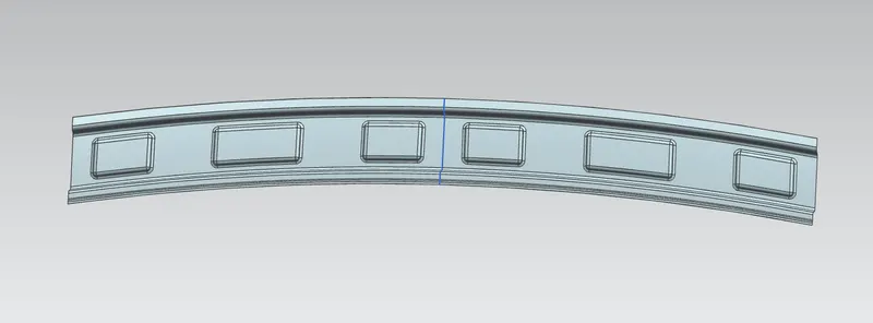
The front roof rail is located on the front of the roof where the wind shield joins with the roof. The visibility criteria and the head room clearance of the passenger are taken into consideration for the bottom flange. one end of rail is joined using spot welding while the other end is joined with the roof using mastic sealants for joining process.
BOW ROOF-1/2:
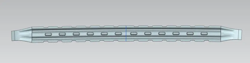
Bow roof is an additional stiffening member for the roof to increase the strength and so that it can satisfy the all Design rules. Both the ends are joined together using mastic sealants to join the part. mastic sealants is only solutions to join the parts without making any aeshtetic impact.
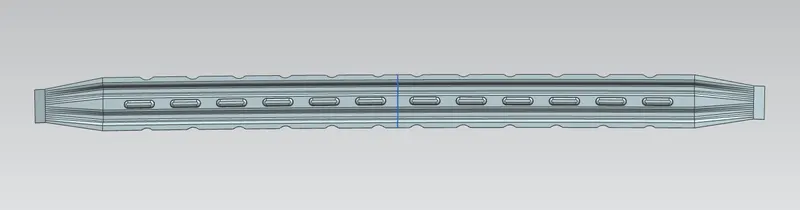
It is used to give strength to the area between the front roof and the centre roof rail. Also it is created in the area between the centre roof rail and the rear roof rail to provide enough strength. It can be created in any numbers depending upon the roof length but the position of the bow roofs is to be justified by Curvature study.
CENTER ROOF RAIL:
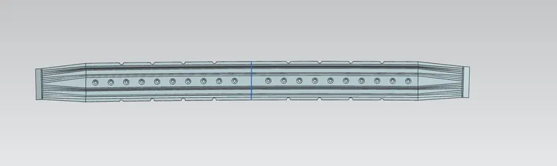
Central roof rail helps in providing effectively support to the flat area of the roof as it is more susceptible to failure under the action of load. generally central roof rail is placed at the center of the roof which is connected to the B-pillar support structure. This central roof rail helps in adding the strength to the roof during the roll-over test. It is connected to the roof by mastic cell.
REAR ROOF RAIL:
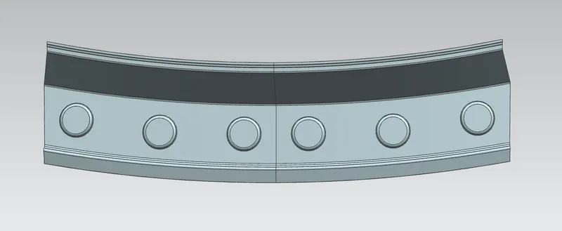
This roof rail joins with the back door and the roof. Inputs from the backdoor are taken into consideration for designing this roof rail. hence one end is joined using spot welding while other end is joined using mastic sealants.
ROOF CRASH TEST:
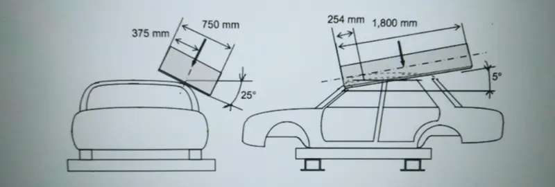
In this test apply the heavy load on the roof and test the strength of roof if it is not under Good strength then it gives an idea to change the curvature of the roof.
Roof crush test is the design given by the IIHS. After analysing the many accidents IIHS has then fixed some regulations, that how to perform the crush test.
IIHS gives the rating based up on this test.
- How fast the car reforms to its original shape after the roll over and
- How deep is the protrusion after the roll over.
This Test helps to minimize the protrusions into the occupant.
HEAT DISTORTION STUDY ON THE ROOF:
Heat distortion temperature is the temperature at which metal softens and deforms under a specified load. while designing roof, this criteria is taken into consideration. we create bow roofs when the roof is long and flat to increase its strength. The position of the bow roofs is to be justified and this justification is done by curvature study.
Bow–roof prediction Formula
W = [1.73 x 10^(-3) x L] + [1.85 x 10^(-8) x (R^2)/t] + [ 1.10x10^(-3) x l] - 2.68
Judgement Condition : OK< 2.7> 3.1
Where
L = Roof Length in X-Direction[mm](Roof dimension in 0-Y)
R = Roof curvature
R = 2(Rx*Ry)/(Rx+Ry)
Rx = X curvature
Ry = Y curvature
t = Roof plate thickness [mm]
l = Bow Roof Span [mm]
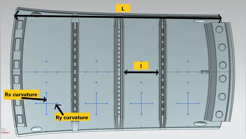
Calculations:

From the above table it can be concluded that all values of W should fall under between 2.7 to 3.5 or atleast less than 2.7 then only design will possible to produce so that based on these values we should request the our styling engineering to change curvature of the roof if agree and change thats fine otherwise we should strengthen the roof by creating the emboss locally.
Snow load Prediction formula
Qr = [Iy x t2] / [α x s x [(Rx + Ry)/2]2 x 10-8]
Note: The Qr value given over here is correct. There was a typo error in the formula given in the video.
Where
α = My x Lx2 x 10-12 , My = Y(Ly-Y)
Judgement condition = Qr ≥ 3.1
250 ≤ s ≤ 380
t = Roof plate thickness [mm]
Ly = Distance between the front and rear roof Rails on the Vehicle along with 0Y[mm]
Length of Roof panel with the center point between Roof rail Front /Rear as the front and rear reference point.
Lx = Distance between the Left and Right end of the roof on the Roof BOW [mm]
Width of the roof panel exposed on the surface.
Y = Distance front Front Roof Rail to Roof BOW[mm]
s = Distance for which Roof BOW bears divided load [mm]
s = L1/2 + L2/2
Iy = Geometrical moment of inertia of Roof BOW (Y cross-section )[mm4]
Rx = Lateral direction curvature radius of roof panel Y cross-section on Roof BOW [mm]
Roof panel curvature Radius of the Length Lx in Front view
Ry = Longitudinal Direction curvature radius of the Roof panel X cross-section on Roof BOW [mm]
Roof panel X curvature radius of length s in Side view
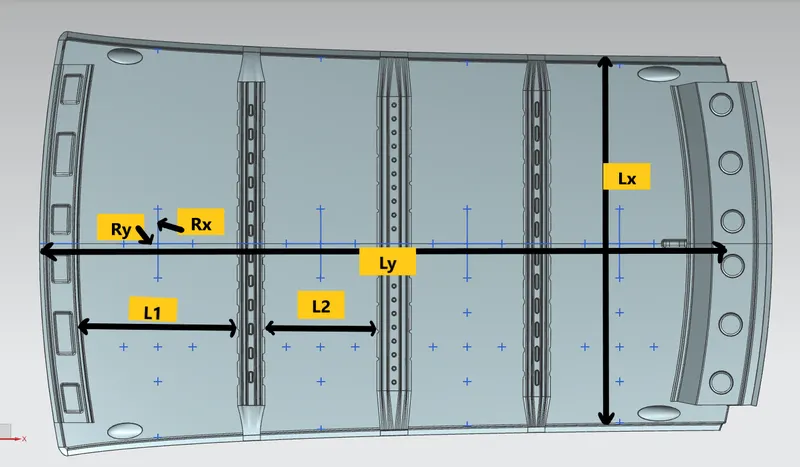
Calculations:

From the above table it can be concluded that all values of Qr should be less than 3.1. then only design will possible to produce so that based on these values we should request the our styling engineering to change curvature of the roof if agree and change thats fine otherwise we should strengthen the roof by creating the emboss locally.
SECTION MODULUS
- Section modulus is a direct measure of strength if any sectional area of an object about an reference axis(neutral axis).
- Strength is nothing but, capable of supporting greater loads. so higher the strength it has a high capable of supporting greater loads.
- This strength can measured directly from section modulus formula, and defined by below formula.
- Section modulus represented with a symbolof 's'.
S=l/y
where
'S' Section Modulus
'I' Moment of inertia
'y' is the Distance from the reference line(neutral axis) to one of the extreme end of an Object.
BOW ROOF-1:
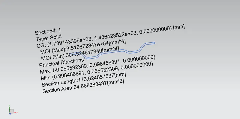
Maximum Moment of Inertia = 3.5166*10^4 mm^4
Minimum Moment of Inertia = 306.52 mm^4
The Total Distance of the section Y= 79.87 mm
To find Section Modulus of section, we have to calculate
= 3.5166*10^4 mm^4/79.87 mm
= 440.29 mm^3(Maximum Strength)
= 306.52 mm^4/ 79.87 mm
= 3.8377 mm^3(Minimum Strength)
BOW ROOF-2
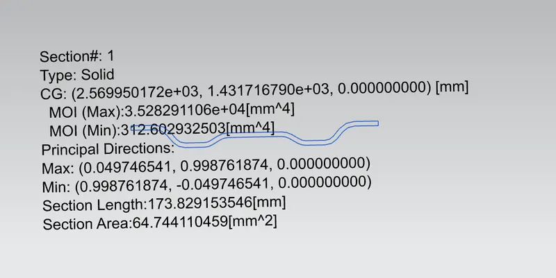
Maximum Moment of Inertia = 3.528X10^4 mm^4
Minimum Moment of Inertia = 312.60 mm^4
The Total Distance of the section Y= 79.95 mm
To find Section Modulus of section, we have to calculate
=3.528X10^4 mm^4/ 79.95 mm
= 441.275 mm^3(Maximum Strength)
= 312.60 mm^4/79.95 mm
= 3.90 mm^3(Minimum Strength)
CENTRAL ROOF RAIL:
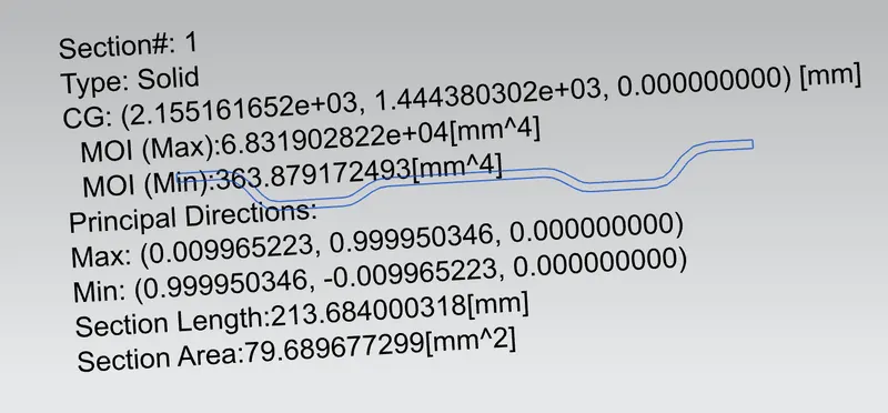
Maximum Moment of Inertia = 6.83X10^4 mm^4
Minimum Moment of Inertia = 363.87 mm^4
The Total Distance of the section Y= 99.91 mm
To find Section Modulus of section, we have to calculate
= 6.83X10^4 mm^4/99.91 mm
= 683.61 mm^3(Maximum Strength)
= 363.87 mm^4/99.91 mm
= 3.641 mm^3(Minimum Strength)
FRONT ROOF RAIL:
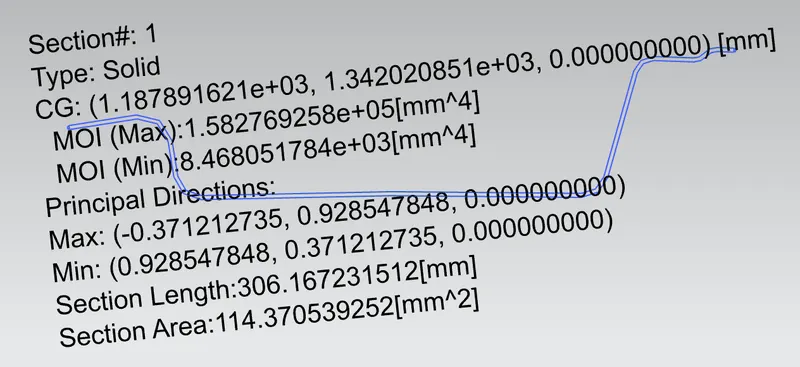
Maximum Moment of Inertia = 1.58X10^5 mm^4
Minimum Moment of Inertia = 8.45X10^3 mm^4
The Total Distance of the section Y=124.64 mm
To find Section Modulus of section, we have to calculate
= 1.58X10^5 mm^4/ 124.64 mm
= 1267.65 mm^3(Maximum Strength)
= 8.45X10^3 mm^4/ 124.64 mm
= 67.79 mm^3(Minimum Strength)
DRAFT ANALYSIS:
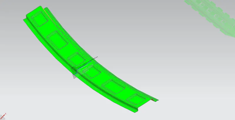
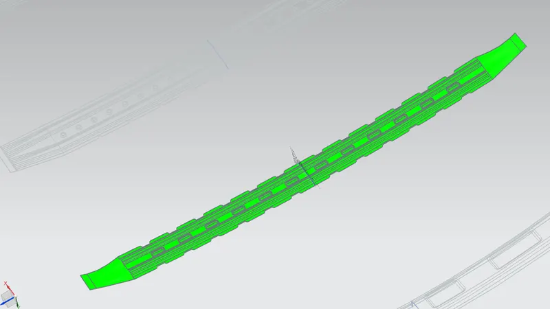
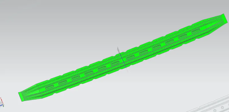
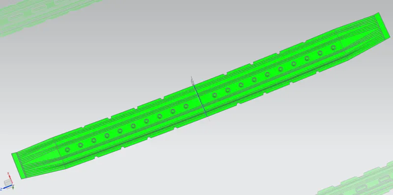
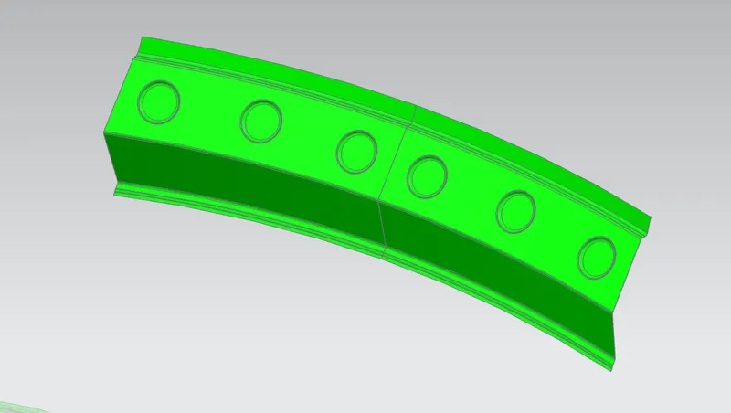
The Draft analysis command enables to detect that part will be easily removed or not.This type of analysis is performed based on color ranges identifying zones on the analyzed element where the deviation from the draft direction at any point, corresponds to specified values.
Minimum draft angle of 7 deg is considered for analysis, green colour infer on the parts that all face along the tooling direction should have positive draft angle greater than 7 deg.
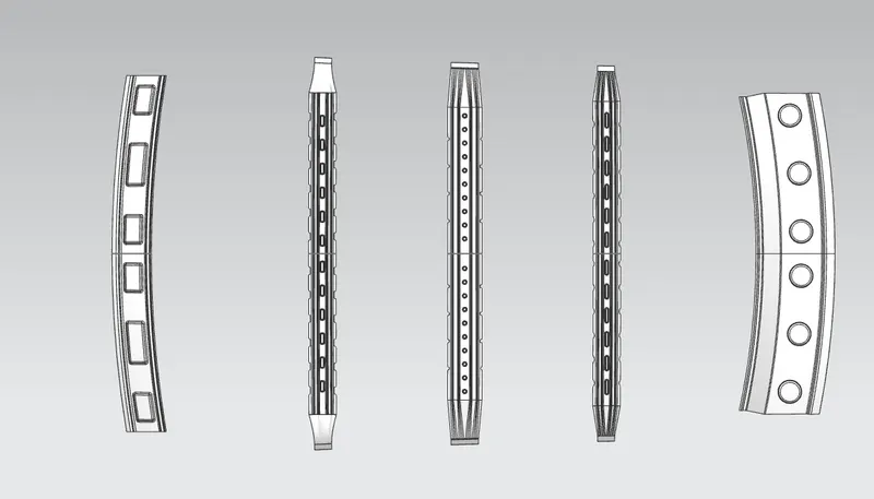
FRONT ROOF RAIL:
BOW ROOF-1:
BOW ROOF-2:
CENTRE ROOF RAIL:
REAR ROOF RAIL:
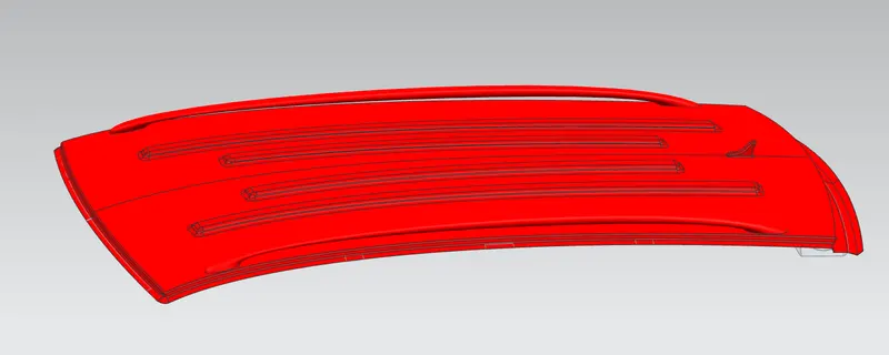
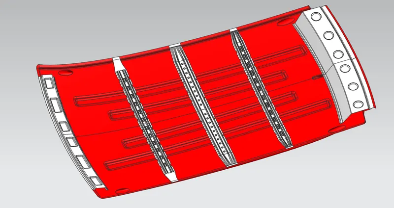
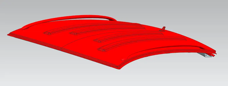
final assembly different view:
CONCLUSION:
Hence the Boof, Front roof rail, Bow roof rails, central roof rail and the rear roof rail is designed by following the master sections and the moment of inertia, Section modulus and draft analysis are carried out to check feasibility manufacturing.