Advanced Sheet Metal Design Using NX Cad Challenge_1_Casing Design
REPORT ON CASING DESIGN USING NX CAD
OBJECTIVES:
- Design the sheet metal using NX CAD.
- Gain knowledege How to Utilise the different NX features and their applications.
INTRODUCTION:
NX formerly known as "unigraphics", is an advanced high-end CAD/CAM/CAE. The NX softwere supports product developing and manufacturing at all stages of the life cycle. NX supports modeling of both complex surfaces and solid models. NX sheet metal provides a set of tools within the NX design of sheet metal parts, dependent on their material and manufacturing process.
DESIGN METHODOLOGY:
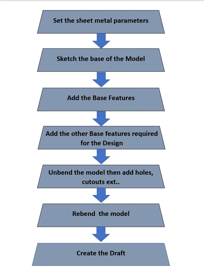
MODEL DESIGN DESCRIPTION:
Features used:
SKETCH:
Sketch is a quick and rough drawing and gives a brief account or gereral outline. It allows designers to quickly visualize multiple design concepts.
TAB:
It gives the base features of the model by adding the material to the given sketches as per the required thickness.
BEND:
Bend used to create the model in required direction & angle.
FLANGE:
It is used to create the an additional body from the edge of the existing sheet metal.
BREAK CORNERS:
It creates the smooth rounded edges.
UNBEND:
Bend the model into its previous state.
HOLE:
Hole is used to create the different type of the holes on sheet metals.
DIMPLE:
Dimple used to create the model by lifting selected area inside the sketch for creating the stamping press to the model.
BEAD:
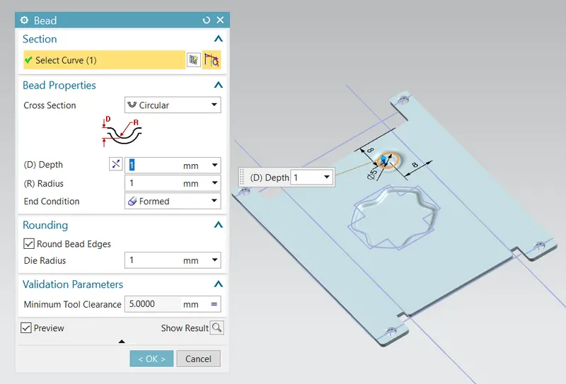
Used to lift the material along selected sketch that stimulates a stamping tools.
MIRROR:
Mirror creates the copy of the body.
FLAT PATTERN:
Used to create a flat pattern from the formed sheet metal.
STEPS USED DURING DESIGN:
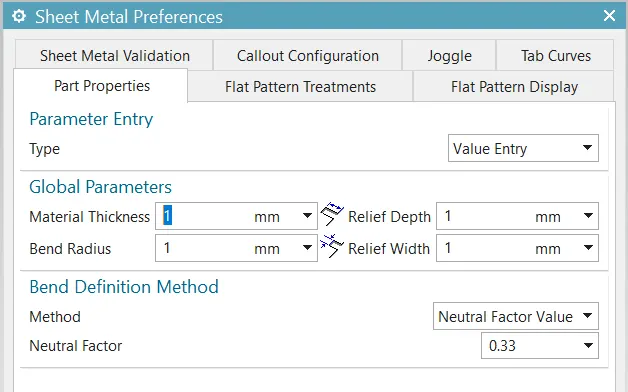
- Set the parameters to 1 mm.
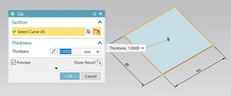
- Create the sketch in XY plane.
- Apply Tab application to the sketch with 1mm thickness.
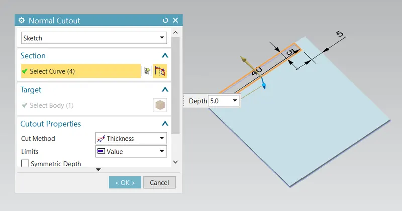
- Draw the rectangular shape sketch on base Tab & Exist the Sketch.
- Use Cutout tool to Create the Rectangular Shape Hole.
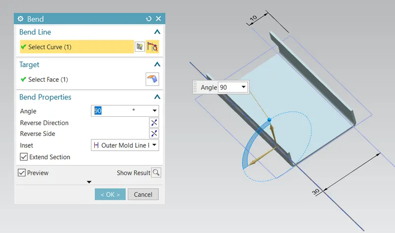
- Bend the Model.
- Draw Two Symmetrical lines on the Tab & Exist the Sketch.
- Then apply Bending Application.
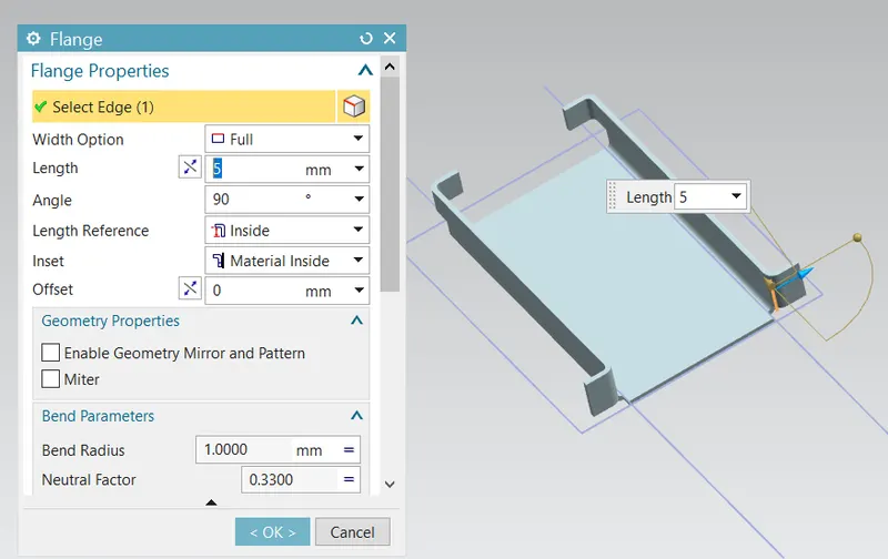
- Add flange.
- Use Break corner & break all the corners with 1mm.
- Unbend the model.
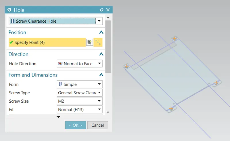
- Create the sketch on Tab as a reference of hole center Ppoint.
- Use the Hole Option to create the hole with referece of Point.
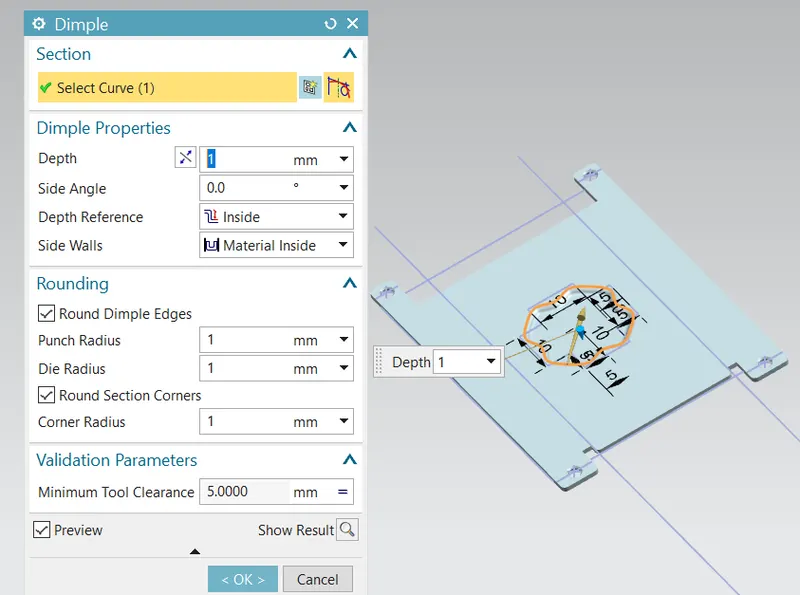
- Create sketch in XY Plane.
- Apply Dimple with depth 1mm.
- Draw circle on XY Plane.
- Apply Bead Tool.
- Mirror the Beads.
- Again Bend the Model.
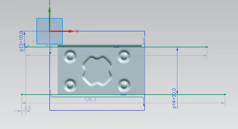
- Hide all the sketches.
- show the solid bodies.
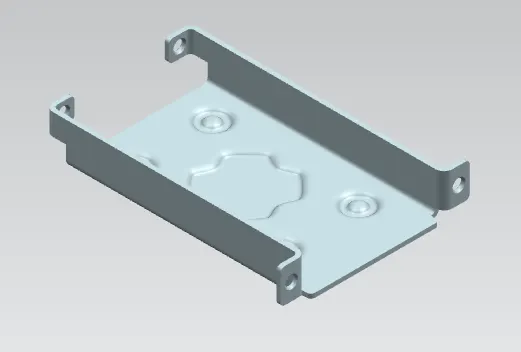
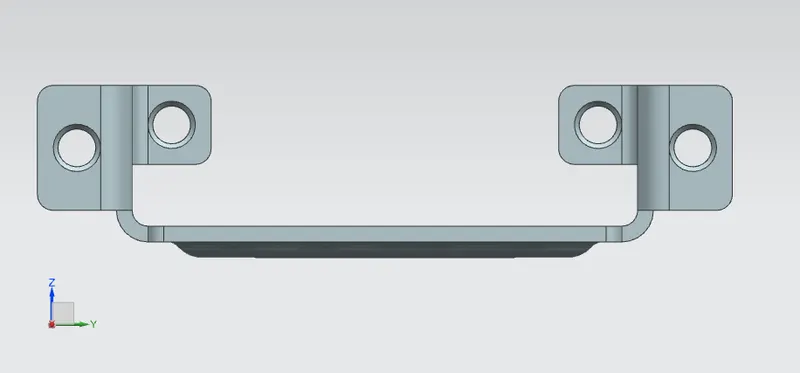
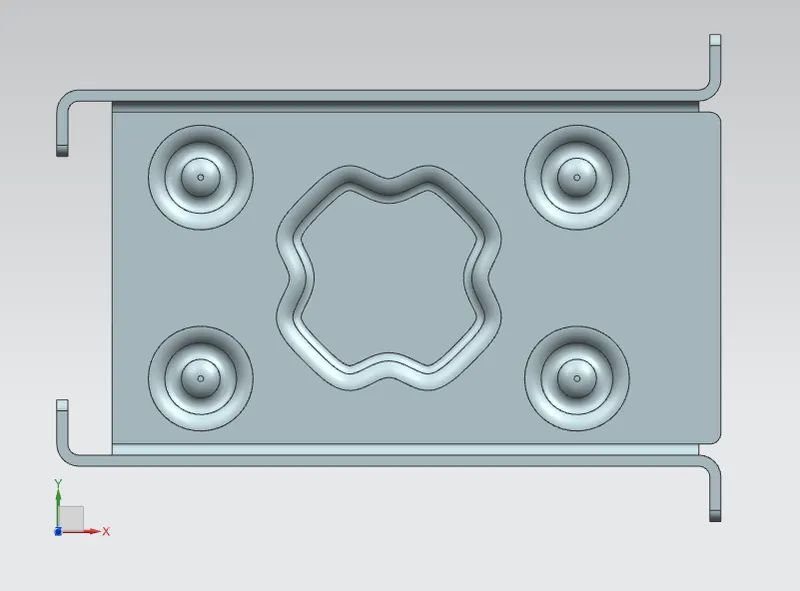
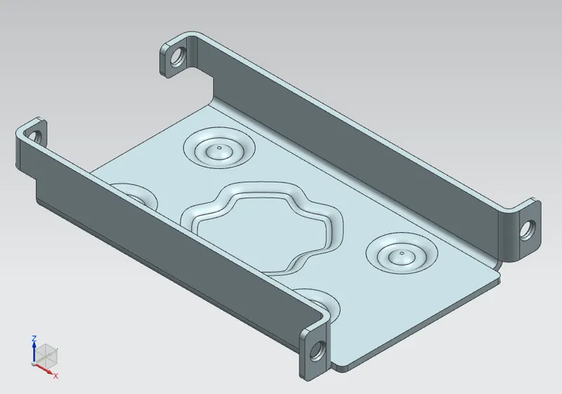
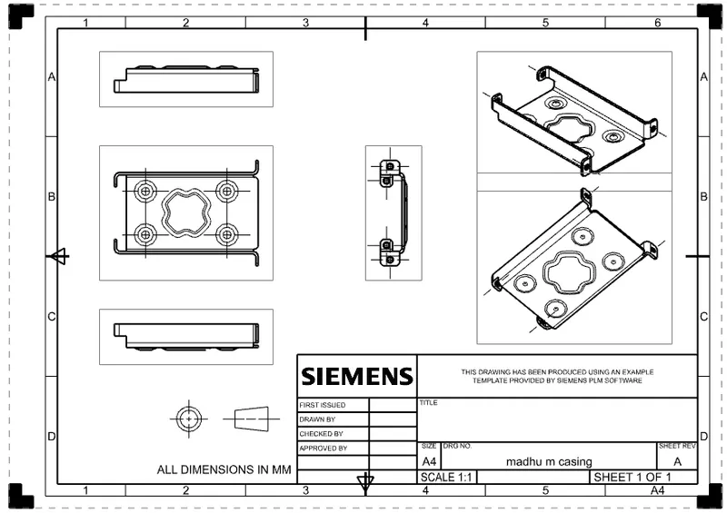
TOP VIEWS OF THE MODELS:
FRONT VIEW
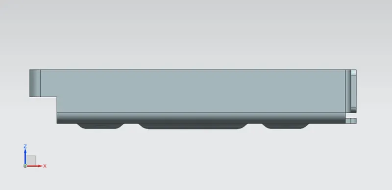
SIDE VIEW
TOP VIEW
ISOMETRIC VIEW
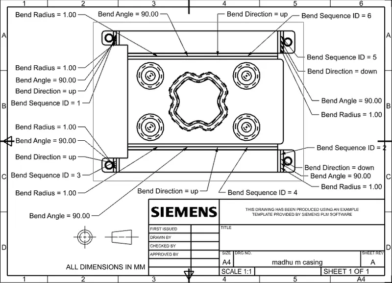
DRAFTED IMAGES
CONCLUSION:
The sheet metal casing is Modelled by Using NX CAD.