Week 11 - Final project
AIM:
To design and development of vehicle interior door trim using Catia V5 with given Class A surface along with Master Section. Also create the B Side features as per design rules.
OBJECTIVE:
- To create thickened part using master section for reference
- To ceate the Mounting features as per design Guidelines in the industry and with master sections
- To Perform the Draft analysis and Tooling analysis.
INTRODUCTION:
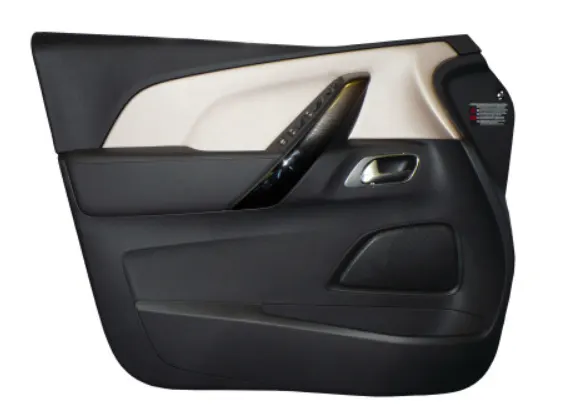
The door panel is the interface between the interior of the car and the inner workings of the door. Generally the door panel is divided into parts for easy designing like arm rest, lower substrate, map pocket. These require one of the toughest requirement among the interior parts of the car. This should be designed to with stand the load while being less than 2 mm in thickness and also to protect the occupants during collisions.
In older cars, door panels used to be made out of cardboard and upholstered with material that matches the rest of the upholstery within the cabin. On the other hand, most modern cars have door panels made from plastic. The door panel covers the internal parts of a car door, such as the wirings.
METHODOLOGY
Creation of Tooling Axis:
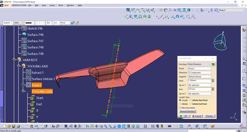
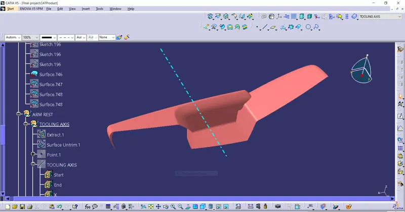
The Tooling Axis is used to find the direction in which the part is removed from the core and cavity the draft angle should be positive to the tooling axis to manufacture the component easily. The step by step procedure of creating the tooling axis is given below.
First create point on Class A Surface by using the on Surface option by setting distance value at zero
Using that point Create the Tooling Axis in Y direction.
Step 1:
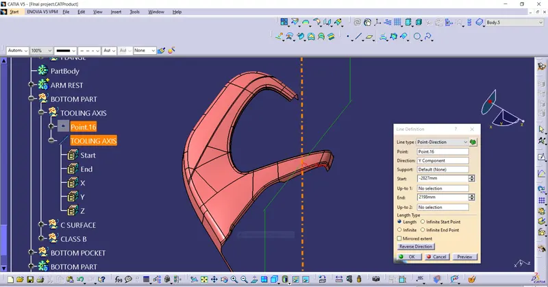
Step 2:
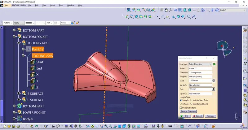
Step 3:
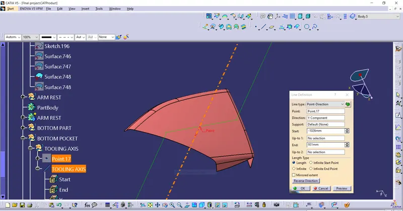
Step 4:
For Arm rest with Main Tooling Axis we should create the side core Tooling Axis Also.
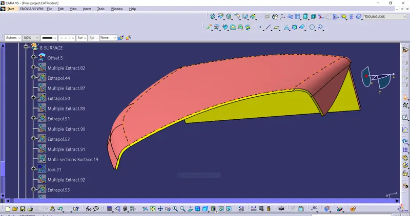
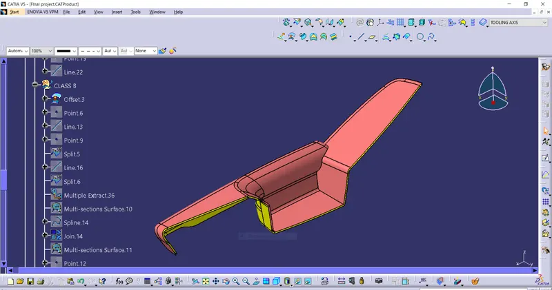
Creating the B Surface.
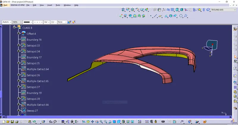
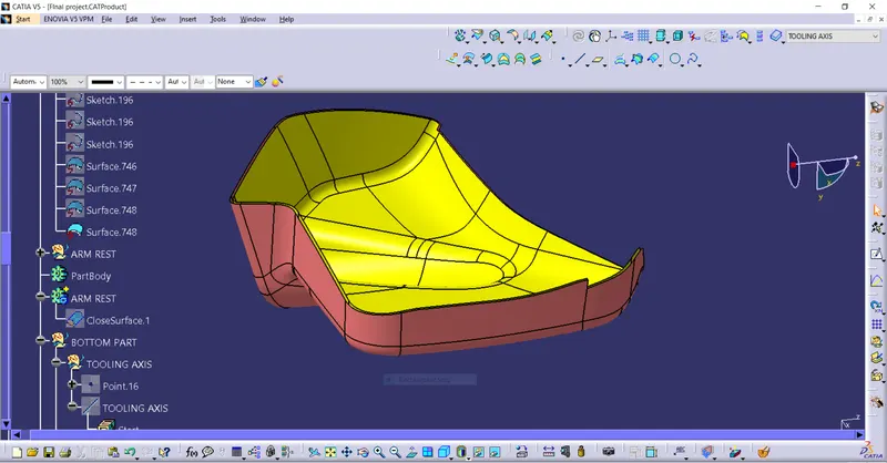
Creating the B Surface by offsetting the class A surface with 2.5mm, by each surafces separately.
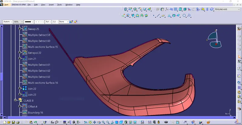
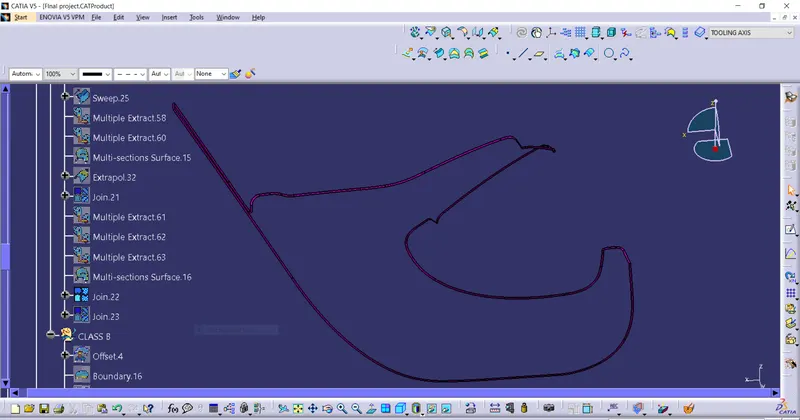
Creation of C Surafce
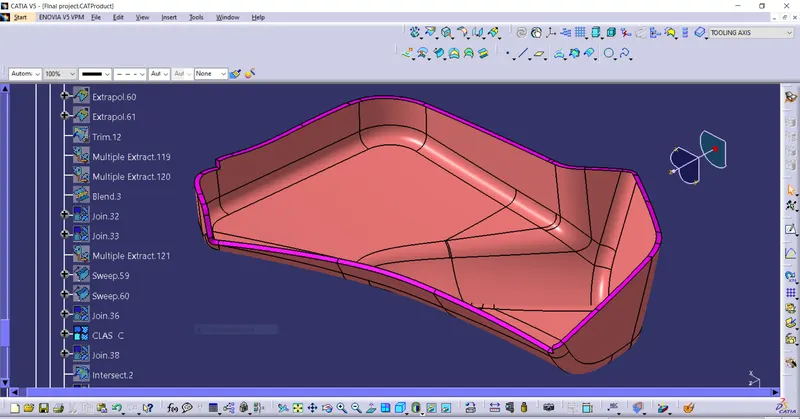
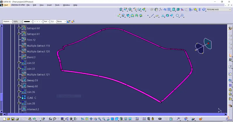
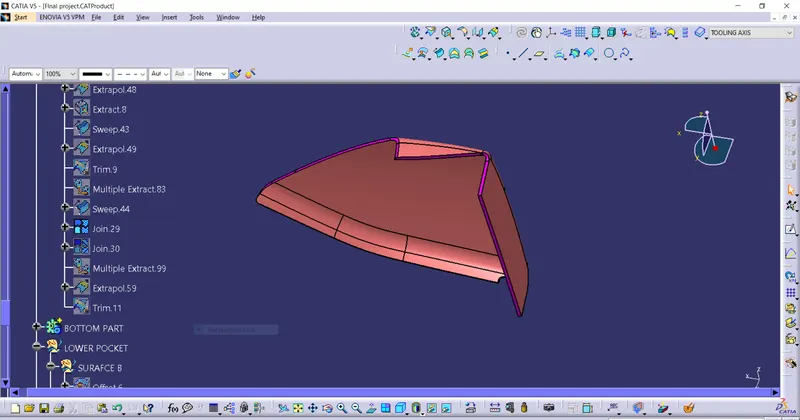
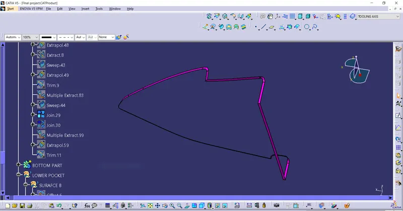
Extract the boundary of class A surafce and it is make into smooth curves to sweep the curves by using support surface to the 90 degree respectively.
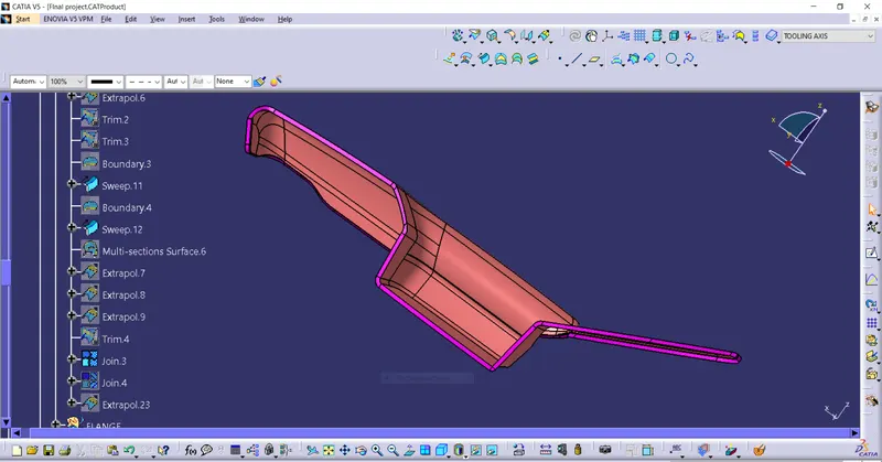
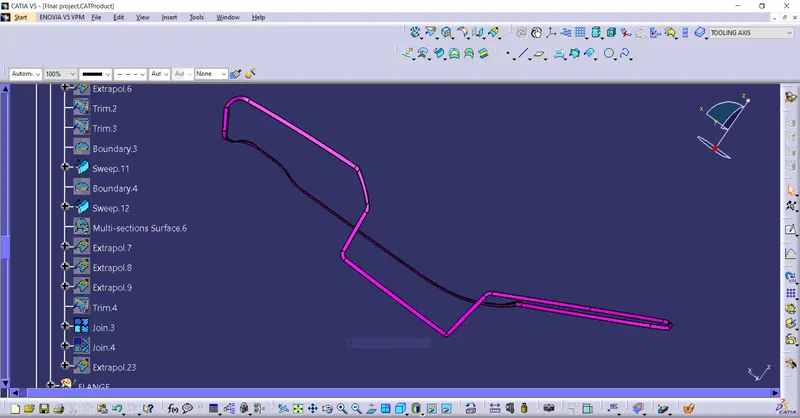
Making of Final plastic Component and Solid Body
First Add class A and Class C Surface.
Then Trim with Class B Surface
Lastly Add Solid Body Using Insert body option in part design as shown below.
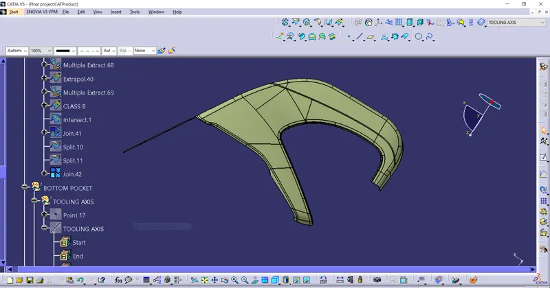
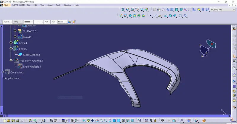
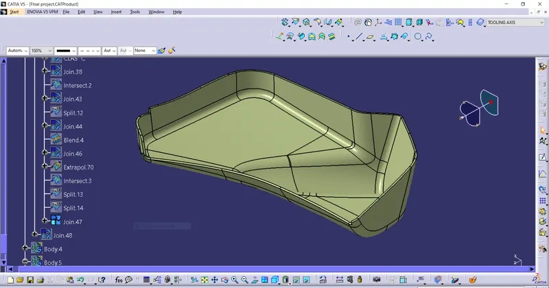
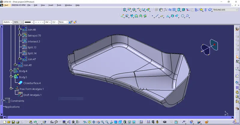
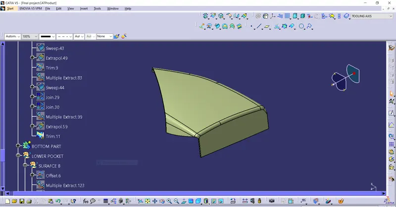
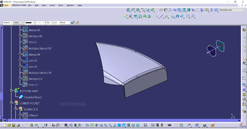
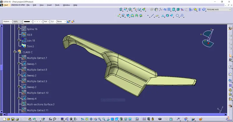
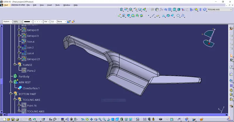
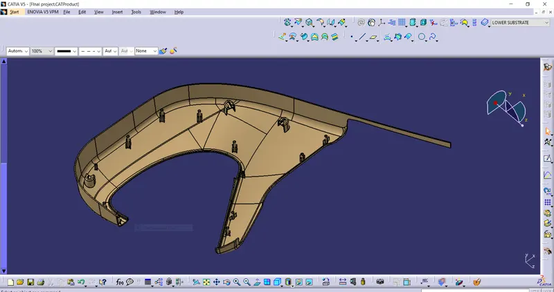
Finally I created All parts with 2.5 mm Thickness now start to add B features on B Surface.
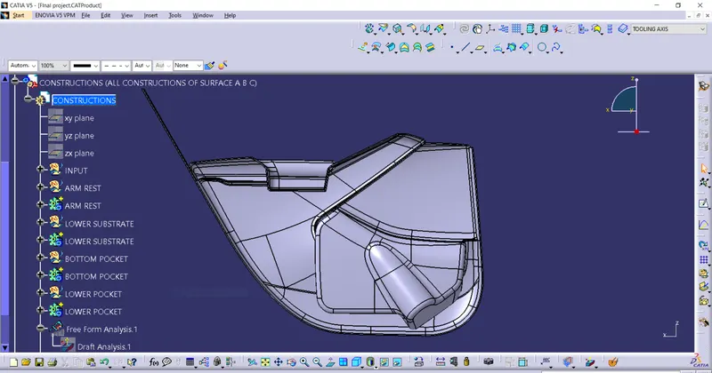
Creation of engineering features:
DOG HOUSE:
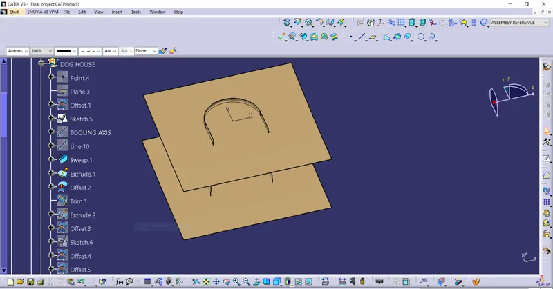
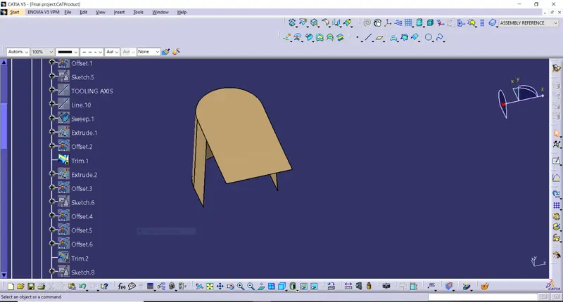
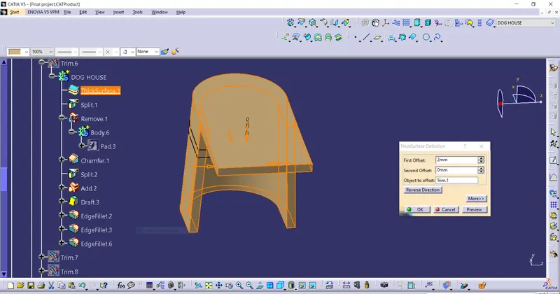
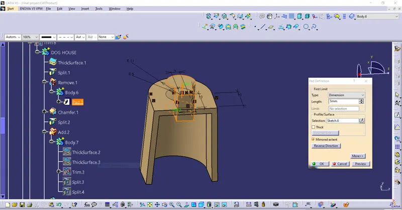
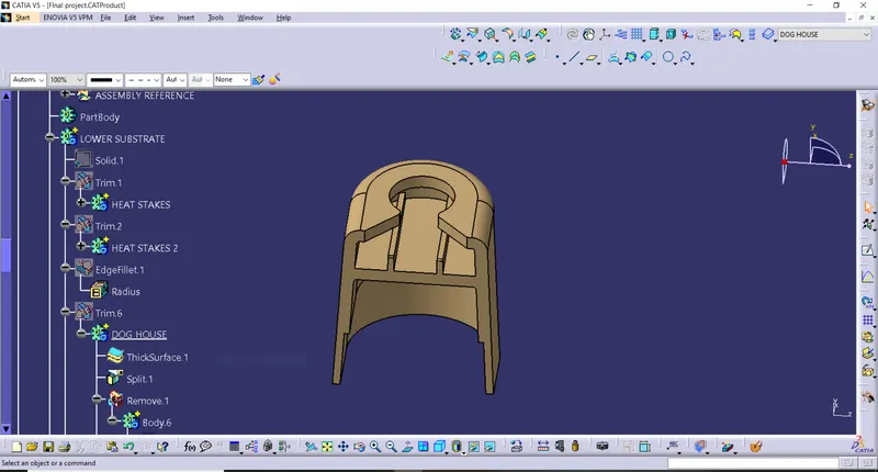
Doghouse is an engineering feature used in plastic trim design Dog house are used as supporting feature. Dog house are subjected to draft analysis to prevent breakage of the component during ejection from mould cavity. Dog house and other enginnering components are built on B surface.
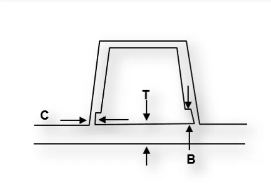
C is where the doghouse contacts the back side of the surface.
Doghouse wall Thickness at the intersection of the part wall (c) should be 40% or less than the main wall stock(T)
Height of (B) should be betwen 3-6 mm.
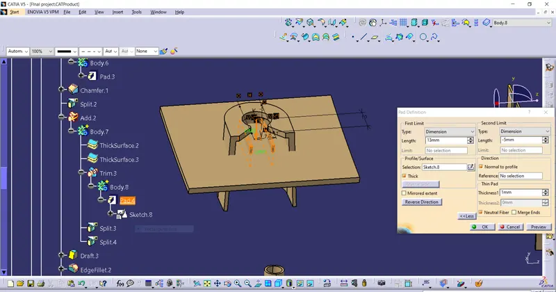
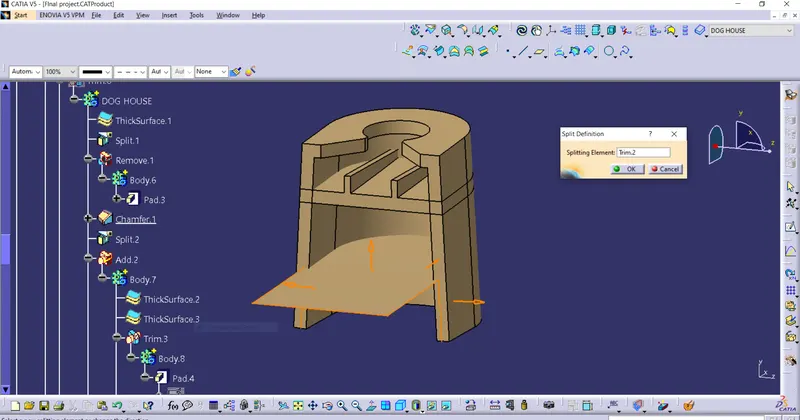
First create the plane to locate the area of the Dog House.
Create the sketch and extrude it.
Then trim it According to our requirement.
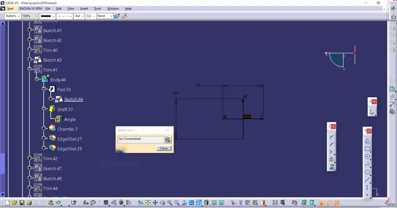
4 WAY LOCATORS:
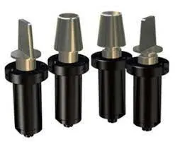
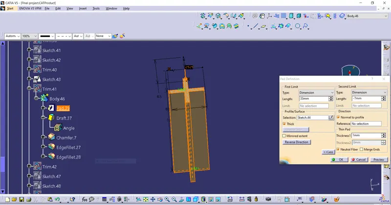
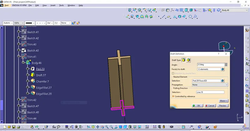
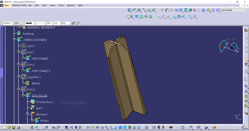
A round locating pin located concentrically in a hole is a common application of a 4-way pin, and helps to further secure the piece. 4-WAY LOCATORS: 4-way mean you prevent movement at 2 axes (+X, -X, +Y and -Y) on the plane. Generally, you have cylindrical pin on the fixture and circular hole at workpiece part.
First create plane according to where we want to create the heat stakes.
Then pad it with the height of 5 times of the thickness of the component.
Draft it with .5 degree.
Add chamfer.
Add fillet.
HEAT STAKES: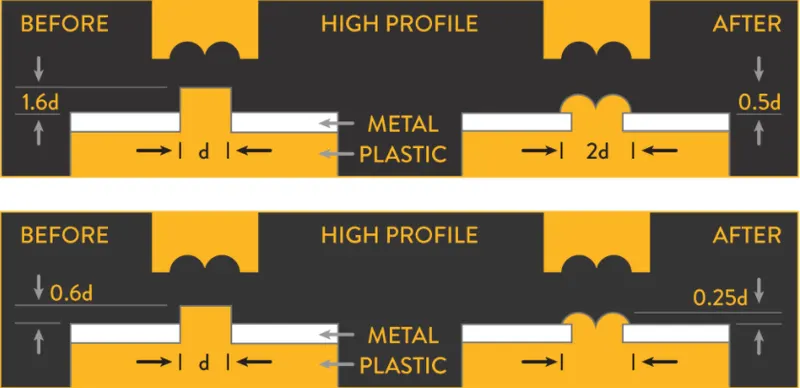
The heat staking tip is brought into contact with the thermoplastic part to be reformed. The heating tip is then heated by direct electrical heating within the tip for a short period of time. The heated tip softens the plastic material and forms the melted plastic into the shape of the tip.
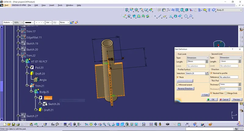
First create plane according to where we want to create the heat stakes.
Then pad it with the height of 5 times of the thickness of the component.
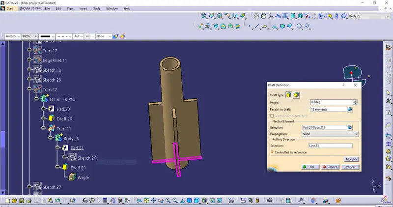
Draft it with .5 degree
Add fillet.
Now create sketch for the ribs which gives the support to the heat stakes.
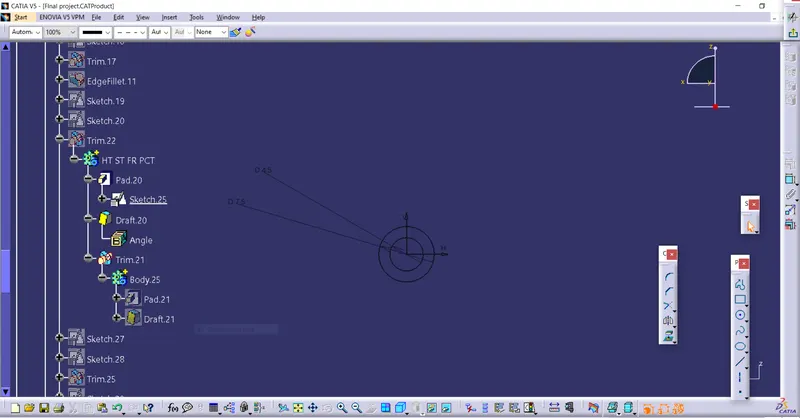
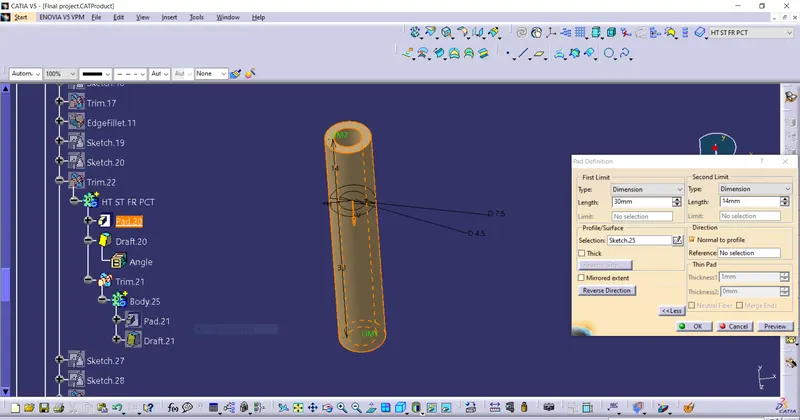
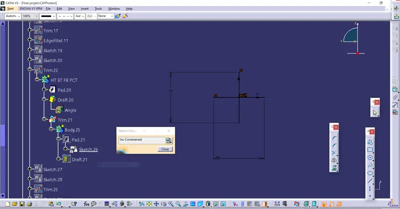
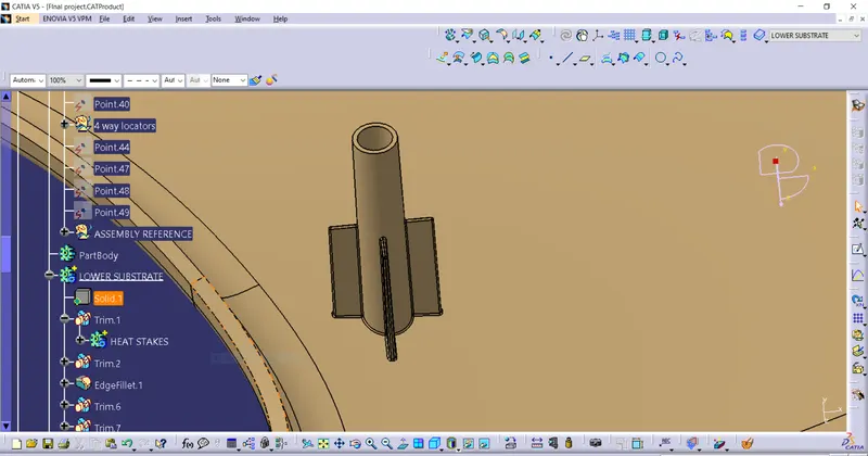
Finally Uniom trim with the main lower substrate.
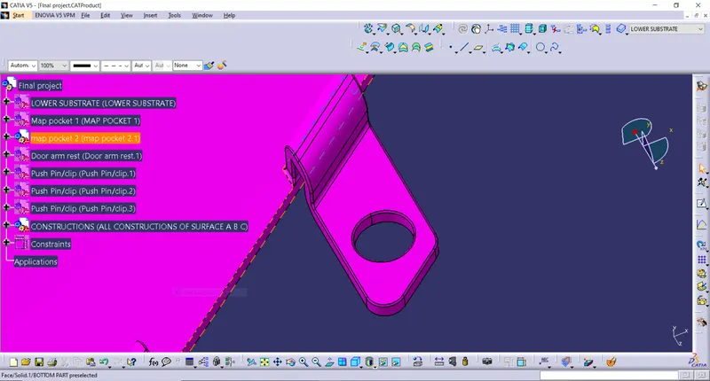
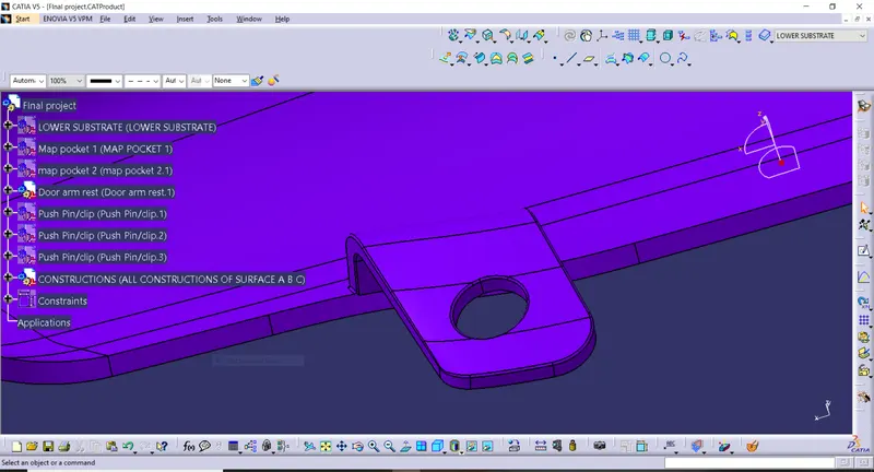
CREATION OF FLANGE:
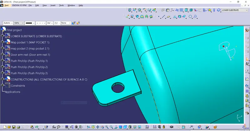
First create the plane on given Master Section.
Extract the flange profile from the Master section in sketch.
Then sweep alomg the edge of the component and fill it on both Sides.
Make it solid,
Finally Add it to the Main Body.
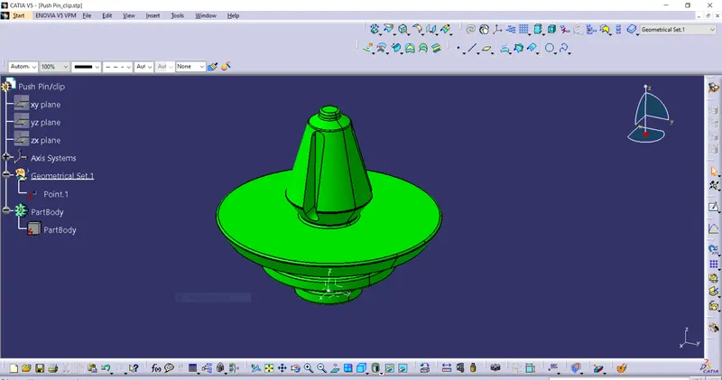
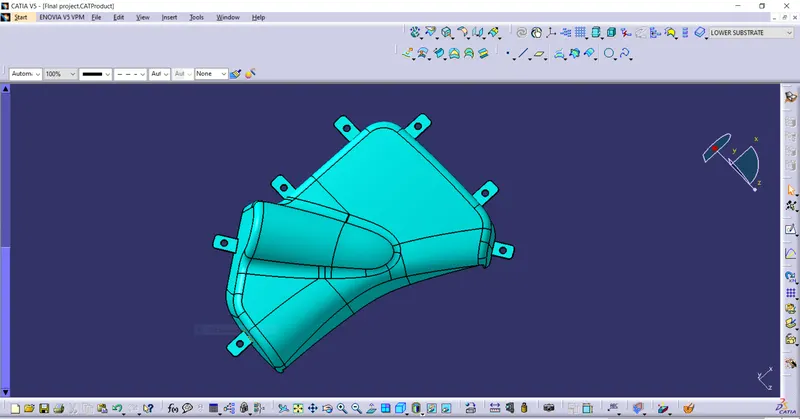
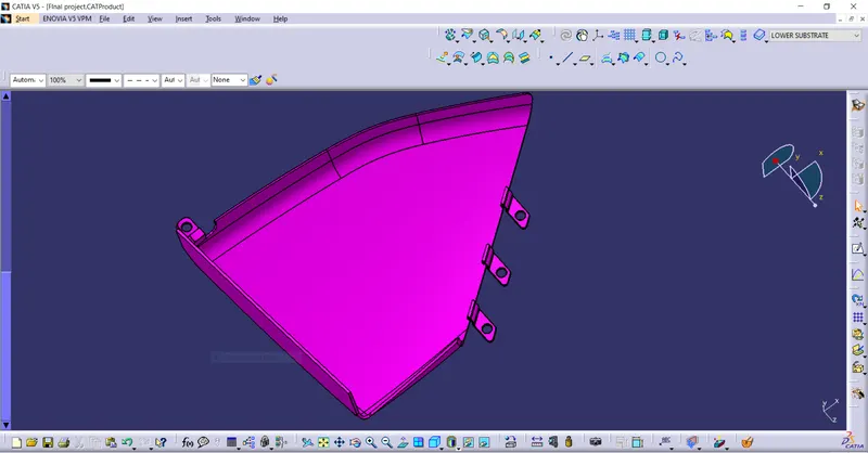
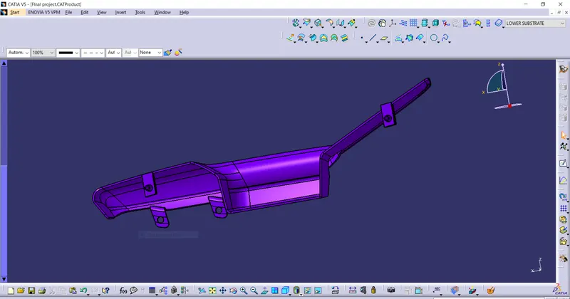
Creation of the push Pin Design
After adding All Engineerimg features
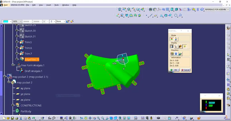
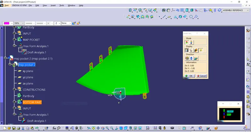
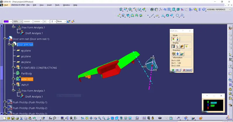
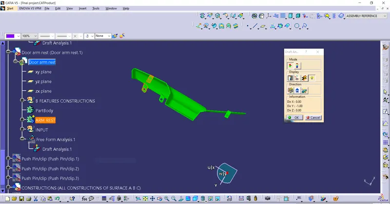
DRAFT ANALYSIS:
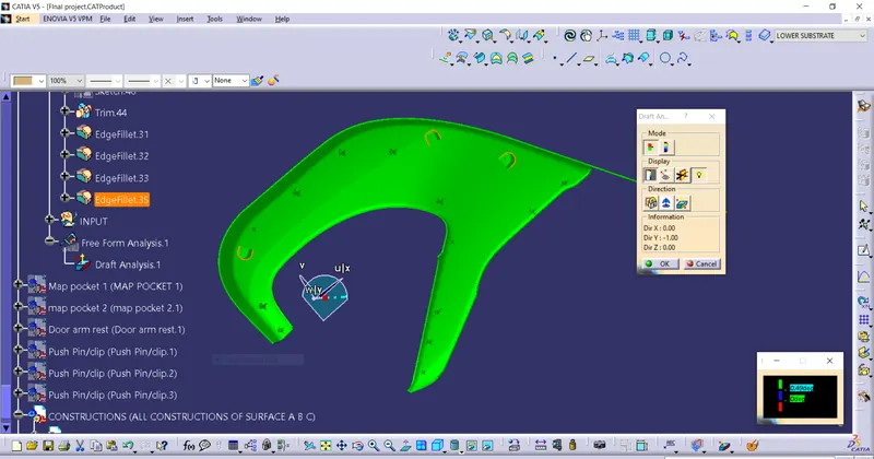
The Draft Analysis command enables you to detect if the part you drafted will be easily removed. This type of analysis is performed based on color ranges identifying zones on the analysed component where the deviation from the draft direction at any point. Corresponds to specified values.
It is one of the easiest ways to improve the quality and efficiency of your injection molding process.
Below from 0 to 0.49 Blue
Above 0.49 Green.
Below 0 Red.
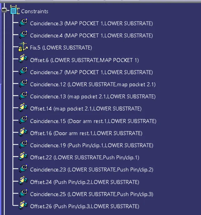
ASSEMBLY:
An assembly is a collection of related parts.
The components in an assembly are defined in relation to each other using assembly mates.
There are two basic methods:
- Bottom up design
Here we first design the model individually then insert into assembly environment.
Here we modify the part individual and that changes seen in the assemly.
- Top down design
Here parts, size, plane, locations can be designed in assembly environment.
Here less rework is needed when design needs change.
FINAL RESULT:
CONCLUSION:
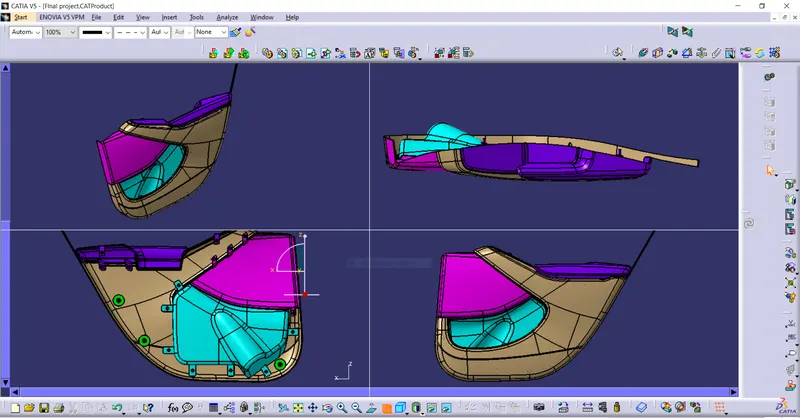
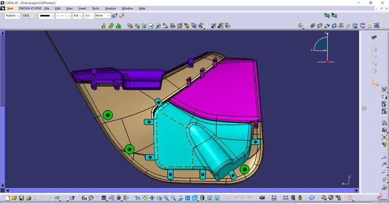
Here i completed Car interior door trim by using given Class A Surface by all require engineering features as per the Design Rules.