Radar Mast & Final Assembly of Yacht
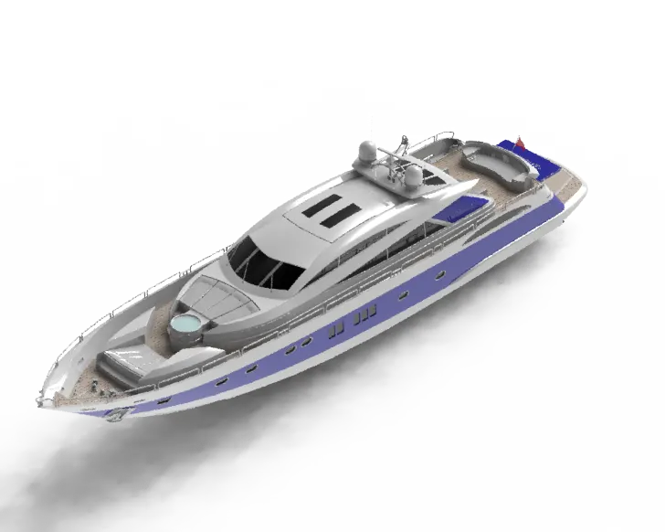
REPORT ON MODELLING SUN SEEKER PREDATOR YACHT
OBJECTIVE:
- Design all the individual parts of yacht with suitable solidworks features.
- Assemble the individual parts by using standard mates in assembly environment.
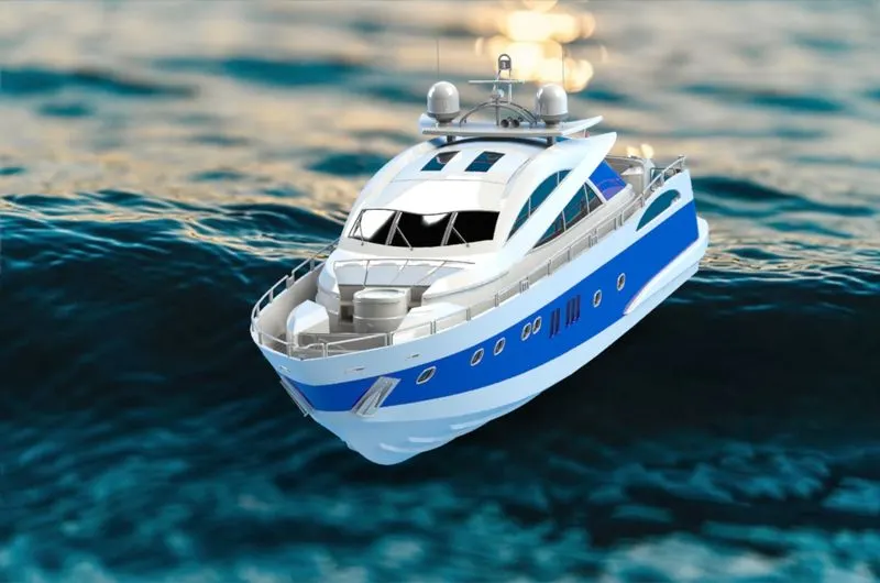
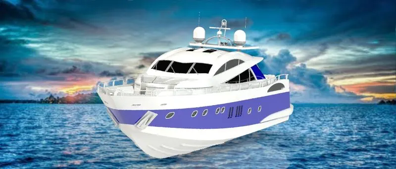
- Render the assembly model by assigning the appearance features like decals, scenes and camera.
- Learn the different techniques of surfacing in the solidworks.
INTRODUCTION:
Solidworks is a CAD modelling software, it provides different type of platforms to perform model designing, photo realistic rendering etc..
Here in this project we used maximum surface modelling commands to complete this project.
YACHT:
Yachts are watercraft used for pleasure and sports. They but nowdays exclusively used for pleasure travels of their owners. The first yachts were built in 1600s in england. Earlier versions of yachts were built from wood or steel. As the technologies grew wood and steel are replaced by fibreglass.
There are 3 types in yachts:
- Weekender Yacht
- Cruising Yacht
- Racing Yacht
DESIGN METHODOLOGY:
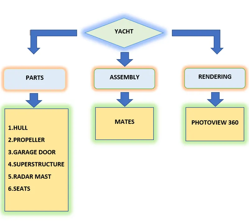
STANDARD COMMANDS USED:
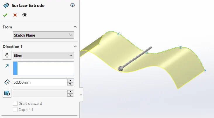
1. EXTRUDED SURFACE
Extrusions create surfaces by tracing a profile curve along a path.
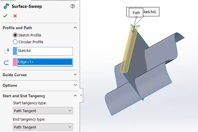
2.SWEPT SURFACE
Sweep Surfaces are surfaces that are generated from a section curve(profile) positioned along a path.
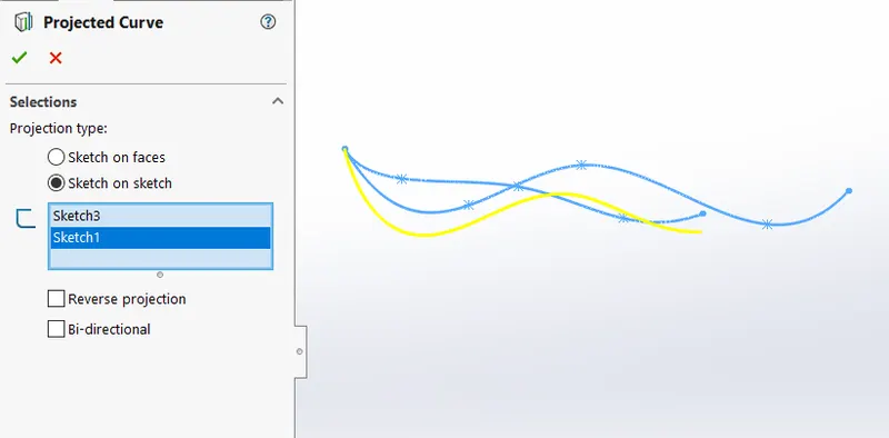
3.PROJECTED CURVES:
It represents the intersection of two different sketches into one single curve.
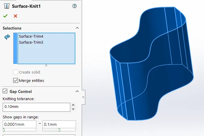
4.SURFACE KNIT:
It used to combine two or more faces and surafces into one. also reduces the gap between surfaces.
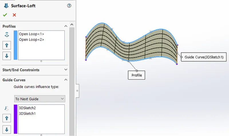
5.SURFACE LOFT:
It is a option to generate the smooth surface between the selected curves.
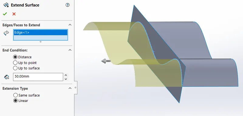
6.SURFACE EXTEND:
It is a option to extend the surface by selecting an edge or multiple edges or a face.
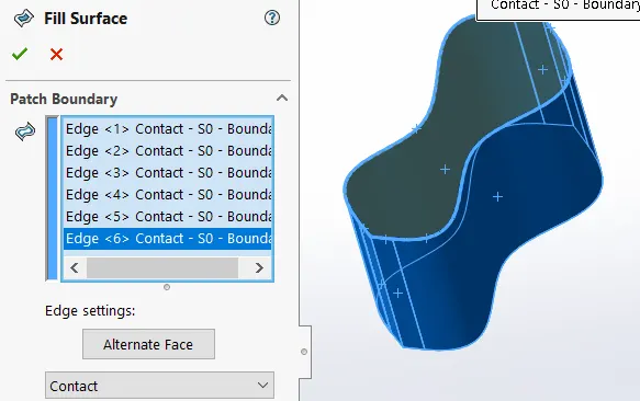
7.SURFACE FILL:
Surface fill used to patch the boundary by generating the surface between the selected existing model edages, sketches.
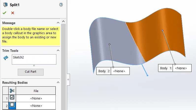
8.SPLIT SURFACE:
It is one of the option which used to divide the faces into multiple regions as defined by the sketch.
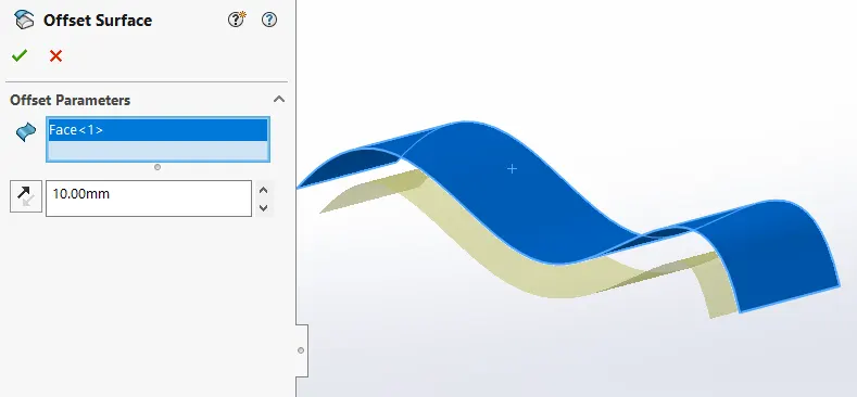
9.OFFSET SURFACE:
It creates a new surface body from selected existing set of faces.
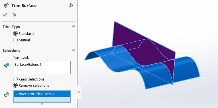
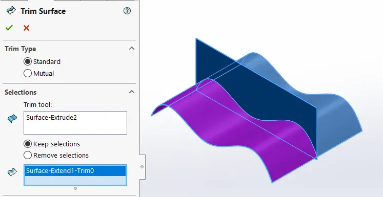
10. SURFACE TRIM:
Surface trim used to remove the intersecting surfaces.
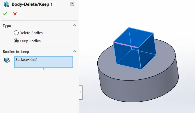
11.DELETE/KEEP BODY:
It is used to delete or keep the selected body while the many bodies and different different bodies present.
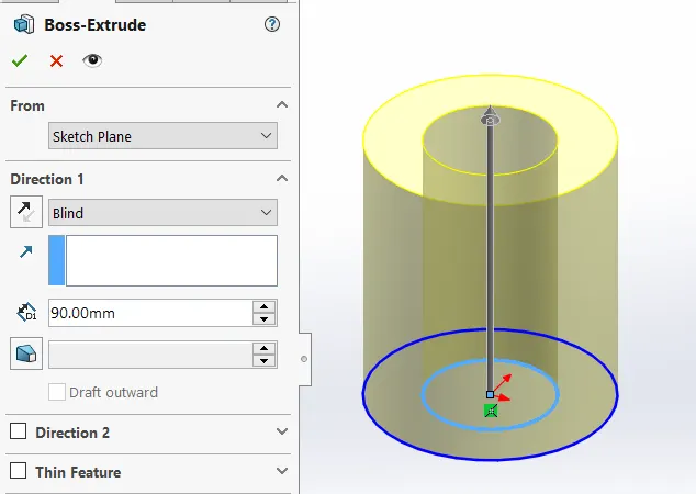
12.EXTRUDE BOSS:
Extrude boss converts the 2D sketch into 3D by adding the material.
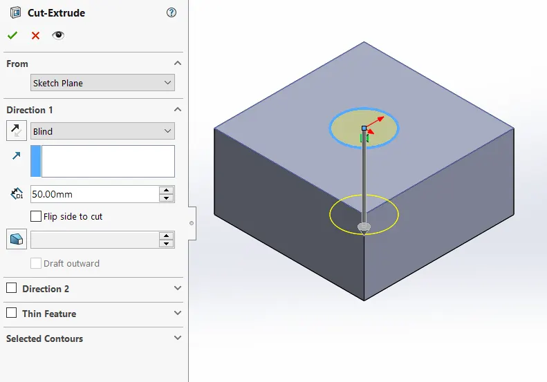
13.EXTRUDE CUT:
Extrude cut Used to remove the material from the model as per sketch shape.
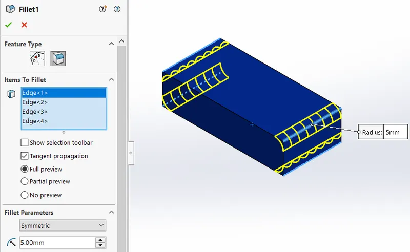
14.FILLET:
It is used to create the round edges.
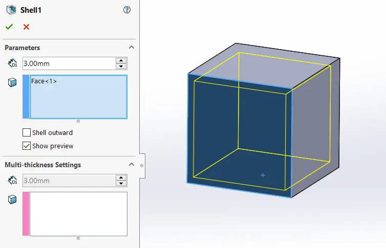
15.SHELL:
It is used to create the hollow body.
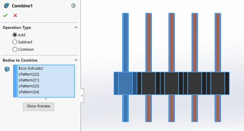
16.COMBINE:
This is used to combine the two more bodies by manually.
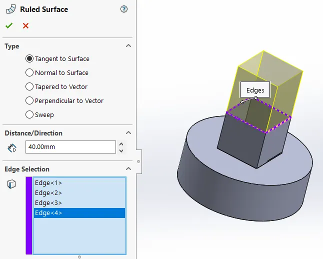
17.RULED SURFACE:
It is used to create the perpendicular surface from the selected edge to the plane also it has option to change the angle of surface.
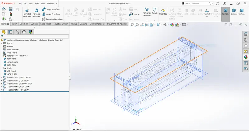
BEFORE GET INTO THE DESIGNING MODEL FIRST WE HAVE TO SETUP THE BLUEPRINTS:
BLUEPRINTS SETUP:
A blueprint is a reproduction of engineering drawing using a contact print process.
or
A blueprint is a guide for making something- its a design or pattern that ca be followed.
PROCEDURE:
- Downloading the sketch picture.
- Open the plane and insert the sketch through sketch picture option.
- Import the sketch and change the diamensions as per the requirement.
- Adjust the transparency tab according to our convinient and finally name the plane.
- Repeat the same procedure for all remaining blueprints.
PARTS:
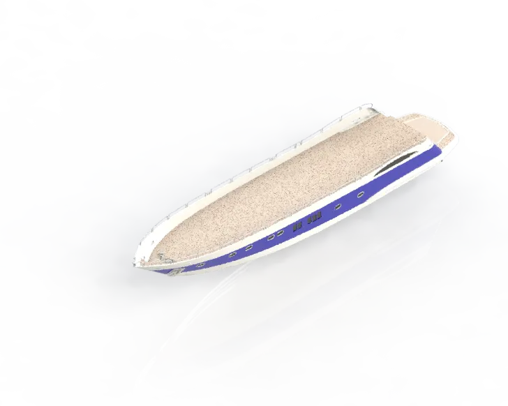
1. HULL
The Hull is the main base part of the yacht. on which every single part is going to mounted.
The line where the hull meets the water surface is called the waterline.
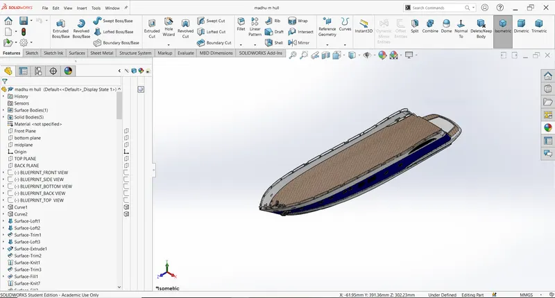
Features used to create the hull:
- Sketch
- Projected curves
- Lofted surface
- Trim surfaces
- Extruded surface
- Knit surface
- Filled surface
- Dome
- Fillet
- Helix
- 3D sketch
- Mirror
- Split body
- Offset surface
- Linear pattern
- Plane
PROCEDURE:
- Setup the blueprint as per the requirement.
- Draw a spline without a midpoint and line on the Bottom plane & adjust blueprint by applying the equal curvature relations.
- Select the midplane create the line & two midpoint spline line.
- Create a projected curve.
- Now create straight line & spline on midplane.
- Then draw spline without midpoint on the bottom plane.
- Create a projected curve.
- Now draw the spline on back plane to close the curves.
- Repeate the above sketch on midplane to close the curves & make it boundary.
- Now apply surface loft.
- Repeate the same sketch on midplane and bottom plane.
- Apply projected curve.
- Close the curves and edge of the loft gap on back and midplane by drawing the spline.
- Apply loft.
- Trim the excessive surface at the tail of hull by drawing the straight line as a trim tool.
- Now draw two centreline from the edge of the lofted surface and close it by line on midplane.
- Apply the loft for the edges and trim it.
- Then fill the open space by selecting upper open edges.
- Apply knit.
- Again fill face by selecting side open edges.
- Create shell.
- Now create extrude solid part up to the shell part of hull by drawing horizontal line on midplane.
- Now select side face of the rectangle extruded body apply offset entities in inward direction.
- Apply extrude cut to the offset sketch and save that cutted body externally in the name of garage door.
- Apply fillet to edges.
- Create new palne as midplane reference and create window according to blueprint.
- Apply sweep as edge of mirror.
- Same way create one more plane flip it.
- Complete sketch of railing of staircase.
- After completing window, staircase,lights,motor, propeller shaft by using midplane mirror all the things.
- Finally change the appearance by applying colour, decals.
- Lastly save the model.
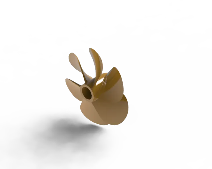
2.PROPELLER
Its Situated under the water and attached to the engine shaft which rotate inside the water. It provides the support to the yacht for easy movement.
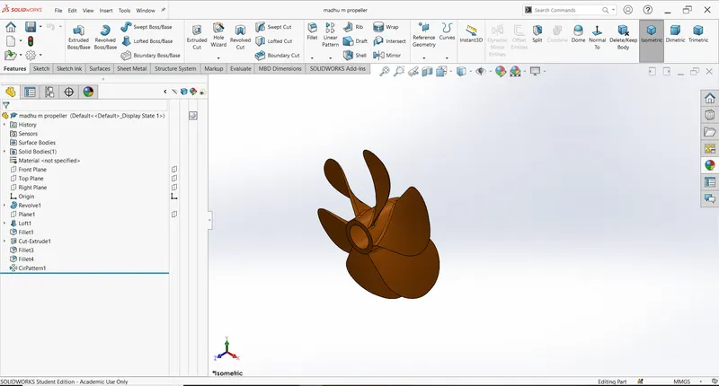
Features used to create the Propeller:
- Sketch
- Revolve
- Lofted Base
- Cut extrude
- Fillet
- Circular pattern
PROCEDURE:
- Open solidworks.
- Create a new skech on right plane as a half conical shape.
- Apply revolved extrude.
- Now select top plane & create rectangle which is inclined on conical body.
- Create new plane as reference top plane.
- Create same sketch on newly created new plane.
- Then apply the solid loft between two rectangle sketches. it forms the blade of the propeller.
- Apply fillet to edges.
- Now select the base of the conical model and draw the circle sketch.
- Apply extrude cut.
- Apply the chamfer to the edge of the blade.
- Finally apply the circular pattern with 6 instances by selecting blade as circular content.
- Lastly change the appearances and save it.
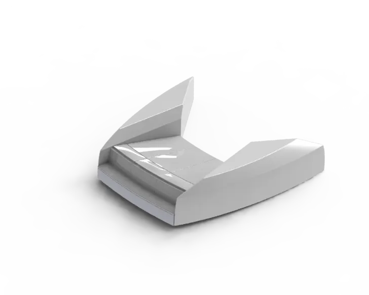
3.GARAGE DOOR
Its a door of the garage. Garage door is used to open the garage of the yacht at the same time we can store anything inside of the garage of the yacht.
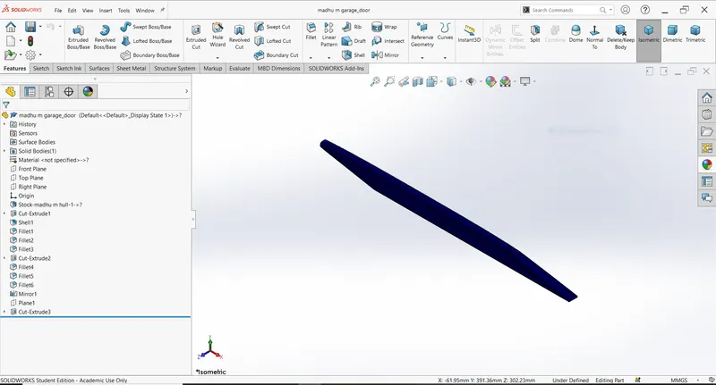
Features used to create the Garage Door:
- Sketch
- Shell
- Cut extrude
- Fillet
- Mirror
PROCEDURE:
- Open solidworks.
- Open the the exported body of the hull (garage door file).
- Select the side surface of body.
- Create the sketch on selected area.
- Apply extrude cut which removes the whole body except door width material.
- Apply shell to side faces.
- Apply fillet.
- Create hole both upper side of the door.
- Mirror it.
- Create the name of yacht on the door by taking line as reference.
- Finally change the colour and save it.
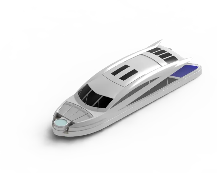
4.SUPERSTRUCTURE:
Superstructure means to add a construction to an already existing structure.
It is a one of most complex design in the yacht. it is a cabin where passenger reside in the yacht. Its a place where captain control the yacht.
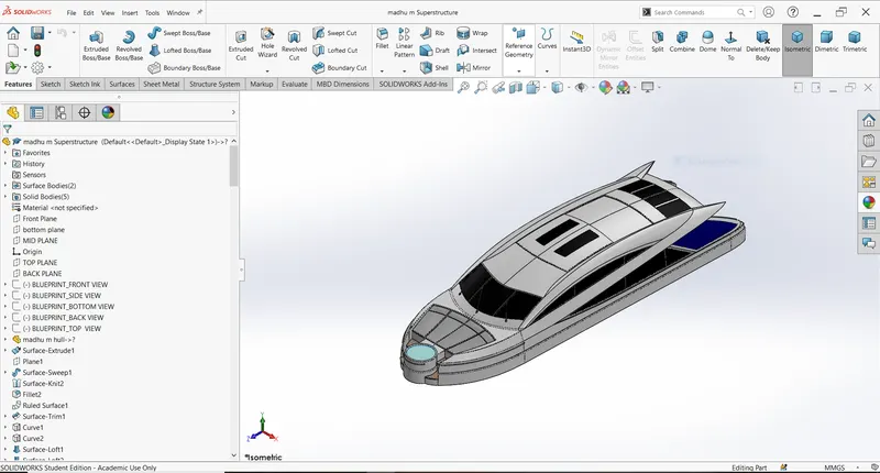
Features used to create the Superstructure:
- Sketch
- Surface extrude
- Ruled surface
- Surface sweep
- Knit surface
- Cut extrude
- Loft surface
- Chamfer
- Fillet
- Mirror
- Combine
- Sweep
- Dome
PROCEDURE:
- Open solidworks.
- Import the deck sorface of the hull.
- Draw the straight line & spline on deck surface with help of the top blueprint.
- Apply the surface extrude for above sketch.
- Create new plane at the tail of superstructure by selecting extruded surface edage as reference.
- Draw sketch on the new plane and apply surface sweep by selecting the extruded surface upper edge as path.
- Apply knit.
- Apply fillet.
- Apply ruled surface by selecting the sweeped surface edges as a reference & change the direction in inwards.
- Apply surface trim at tail portion with sketch as trim tool.
- Select mid plane apply the convert entities to the upper edge of surface & close it.
- Select top plane again apply convert entities to the upper edge of the surface.
- Create projected curve.
- Select top plane offset the edge of the superstructure.
- Then draw the sketch on midplane & close it.
- Create projected curve.
- Close above 2 curves by using staright line in 3D sketch.
- Apply surface loft.
- Fill the remaining gap with appropriate sketch & features.
- After completing the surface of the body knit it.
- Select deck and create circle.
- Extrude and apply fillet.
- Trim the unwanted surface.
- Select bottom plane apply the convert entities to the open edge of the superstructure.
- Extrude the surface.
- Trim the remaining surface.
- Knit it with solid form option.
- Apply dome to front glass part of the superstructure.
- Apply surface offset, surface trim whenever it needs.
- Create plane as per requirement.
- After completing the glass, windows, tail & all the parts change the appearance.
- Finally save the model.
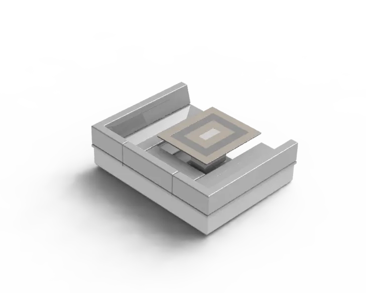
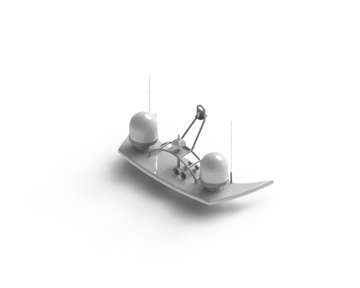
5.RADAR MAST
They are electronic navigation instruments that use to generating a picture of the ship's surroundings on a display screen.
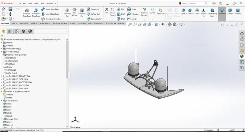
Features used to create the Radar Mast:
- Sketch
- Boss extrude
- Revolve
- Sweep
- Dome
- Shell
- Fillet
- Chamfer
- Mirror
PROCEDURE:
- Open solidworks.
- Import the top surface of the superstructure.
- Select midplane and draw the line as the base of the radar mast.
- Create new plane that above sketch as reference.
- Create new sketch on new plane same as base of the radar with splines.
- Extrude it.
- Apply fillet.
- Create new plane as reference front plane.
- Draw the sketch as excactly as dome of radar.
- Revolve it.
- After creating the all the shafts on one sides apply the mirror by selecting midplane as a reference.
- Change the appearance and save it.
6.SEATS
a. FRONT SEAT
It is a front seat of the superstructure. which gives the best front view of sea for passengers. In yacht front seat is called as Bow.
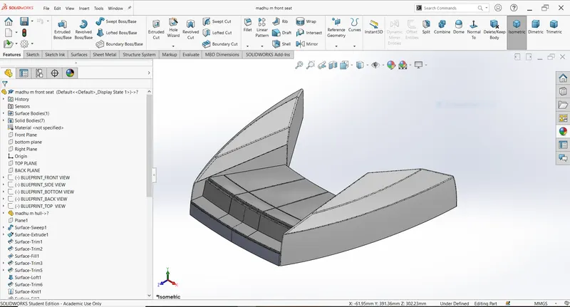
Features used to create the Front seat :
- Sketch
- Sweep surface
- Surface trim
- Surface extrude
- Surface knit
- Surface loft
- Revolve
- Chamfer
- Fillet
- Dome
- Mirror
PROCEDURE:
- Open solidworks.
- Import deck suface.
- Create sketch on the deck surface with the help of splines by using top blueprints.
- Create plane at the end of the above spline.
- Draw spline in the new plane.
- Apply surface sweep.
- Again select deck surface draw v shape lines connect the lines to the edge of the sweep with pierce.
- Apply surface extrude.
- Trim excessive surface.
- Finally fill the surface by selecting upper biundary edges.
- Trim the edges and convert them to inclined shape by applying loft.
- Apply knit,
- Apply fill surface for the bottom edges by hiding deck surface.
- Apply knit with form solid body option.
- Apply fillet.
- Create revolve by creating sketch on side of the solid body.
- Apply dome after creating all the inner single things mirror it.
- Change the appearance and save it.
b. MIDDLE SEAT
It is situated the back of the Superstructure. It is ergonomically designed to provide the seating for the multiple passengers.
also it has the table at center.
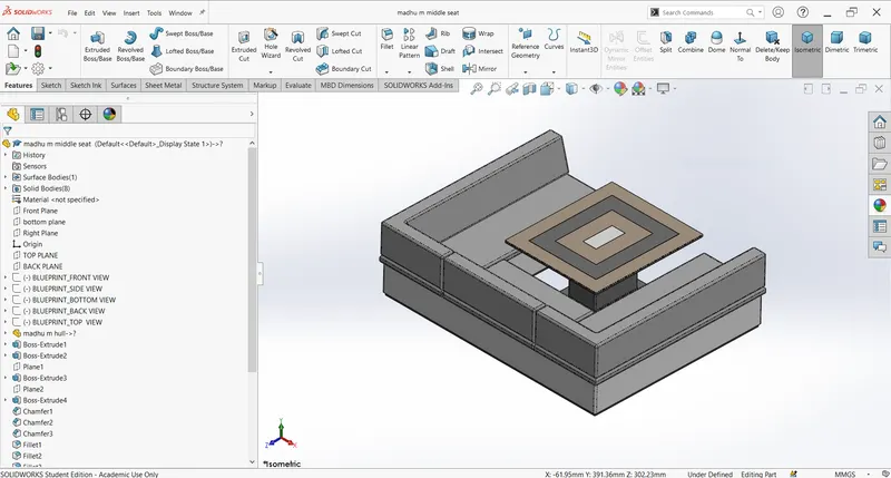
Features used to create the Middle Seat:
- Sketch
- Boss extrude
- Cut extrude
- Chamfer
- Fillet
- Mirror
PROCEDURE:
- Open solidworks.
- Import deck suface.
- Draw sketch on the deck surface as per the blueprint.
- Extrude it.
- Select surface of extrude body apply offset outwards again extrude it.
- Create new plane with reference of above extruded body upper surface.
- Create the same sketch like the edge of below the extruded body.
- Extrude it.
- Apply chamfer.
- Apply fillet.
- Mirror it.
- Change appearance and save it.
C. REAR SEAT
In the yacht rear seat called as Stern. It is situated at the end of deck surface. Also Its provide the seating for the passengers and provides best back view from yacht.
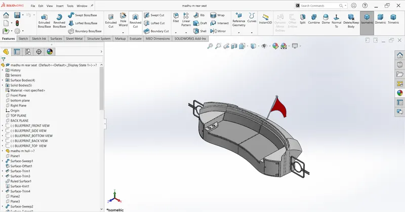
Features used to create the Rear Seat :
- Sketch
- Surface sweep
- Surface offset
- Surface trim
- Ruled surface
- Surface knit
- Surface extende
- Surface loft
- Boss extrude
- Cut extrude
- Fillet
- Chamfer
- Mirror
- Revolve
PROCEDURE:
- Open solidworks.
- Import deck suface.
- Select midplane adjust blueprint with splines line at tail.
- Create plane as a reference of previous spline sketch & deck surface.
- Draw the spline an the new plane as a path for sweep.
- Apply surface sweep.
- Apply surface offset outwards for the sweep surfaces.
- Trim the unwanted portion of the offset.
- Apply knit.
- After filled all opened faces with the help of the sweep, extended, extrude, fill and loft.
- Knit it and close the shape with extrude by applying the convert entities to the inner edges of surface on the deck surface.
- Fill the side open edges with surface loft.
- Knit it.
- Fill the bottom open faces with the fill option.
- Finally knit and convert it to solid body.
- Unhide the deck surface.
- Draw the sitting face with splines and extrude it.
- After completing all single things simply by selecting mid plane mirror it.
- Finally change the appearance and saved it.
7.RADAR
Radar is a device which use to detect the obstacles.
It used Soundwaves to detect the obstacles.
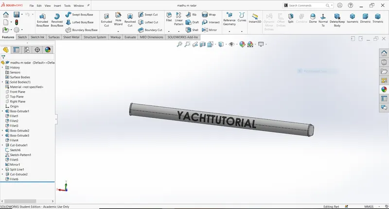
Features used to create the Radar:
- Sketch
- Boss extrude
- Fillet
- Cut extrude
- sketch pattern
- Mirror
PROCEDURE:
- Open solidworks.
- Draw the sketch on the right plane.
- Extrude it.
- Apply fillet.
- Select the side of the extruded model.
- Apply the offset in outwards.
- Extrude it.
- Mirror the whole extruded part by selecting midplane as referencce.
- change the appearance and save the model.
ASSEMBLY:
An assembly is a collection of related parts.
The components in an assembly are defined in relation to each other using assembly mates.
There are two basic methods:
- Bottom up design
Here we first design the model individually then insert into assembly environment.
Here we modify the part individual and that changes seen in the assemly.
- Top down design
Here parts, size, plane, locations can be designed in assembly environment.
Here less rework is needed when design needs change.
HERE WE USE BOTTOM UP DESIGN
Features used to create Assembly:
- Mates
Mates:
Mates create geometric relationships between assembly components.
when we apply the mates that define the allowable directions of linear or rotational motion of the components.
- Coincident mate: A Coincident mate positions two vertices/faces/edges for contact.
- Concentric mate: Selected items can share the same center point.
- Distance mate: Selected items define specified distance between them.
PROCEDURE:
- Open solidworks & select the new assembly option.
- Insert the existing chassis file click ok it will fixed automatically.
- For remaining parts insert the file and use the distance, concentric, width and coincident mates.

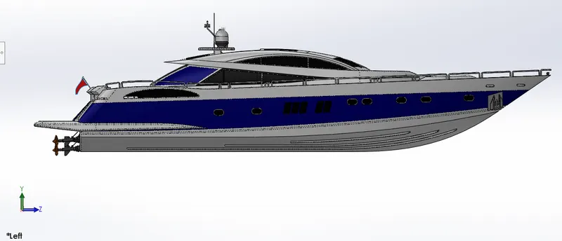
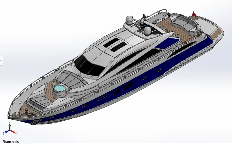
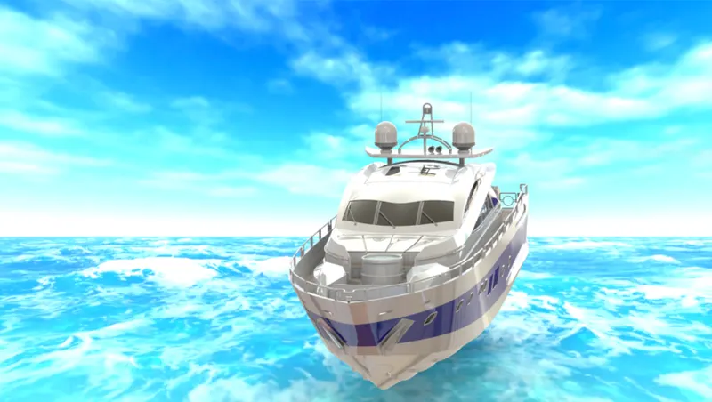
RENDERING:
Rendering is the process of creating realistic images of the photorealistic model with the environment.
There are two applications to get the rendering images.
- PhotoView 360
- Solidworks Visualize
HERE I USED PHOTOVIEW 360
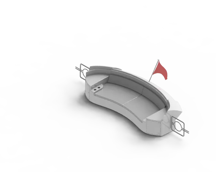
PhotoView 360 produces photo realistic rendered image of models.
PROCEDURE:
- Click Tools>Add-In & add in photiview 360.
- Start a preview in the geaphics area.
- Edit appearances, the scene and decals,
- Edit lights.
- Edit PhotoView Options.
- Perform a final render.
CONCLUSION:
- All the parts of yacht modelled by Using the Solidworks.
- Learnt about how to use surface modelling features.
- Got advanced knowledge of solidwoks.
- Arun Kumarhi bro this is arun from harihar contact me at 335me16301 @gmail.com i wanted to contact with you