Door Arm Rest Week 8 Challenge
AIM:
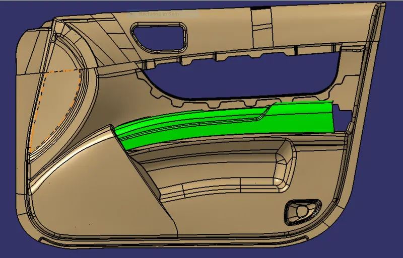
Creation of Door Arm rest and add thickness to it.
OBJECTIVE:
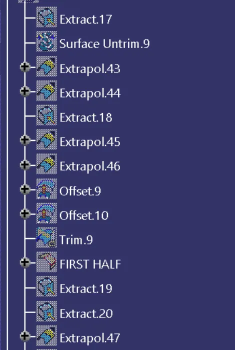
- Creating the B and C surface.
- Creating the Tooling Axis.
- Performing the Draft analysis.
Tooling Axis:
The tooling direction is used to find the direction in which the part is ejected out of the mold. The draft on the part should be positive in oeder to manufacture the part easily. The draft angle should be positive with respect to the tooling direction.
DRAFT ANALYSIS:
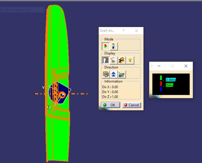
Draft analysis is a method of checking the draft angle on various faces of a part with a particular direction. This type of analysis is performed based on color ranges identifying zones on the draft direction at any point, Corresponds to specified values.
PROCEDURE:
1. Setting the main Tooling Axis:
- First check the connectivity of the class A surface using boundary option. Ensure that there is no gap between the two surfaces.
- To create the Tooling axis we need the proper orientation or view that gives the correct features and draft available in the componenet.
- Here the Components view for the tool to see the features present in the geometry.
- Now create the axis system at the center point of the hole.
- Now create the Axis system at the Center point of the Hole.
- Now using the intersection option, in sketch mode we should create the reference 2D Sketch of Door Arm Rest viewing from X direction.
- Then draw the two lines on supporting side wall intersection lines.
- Now using the these 2 lines create a bisecting line from reference point in Z direction. This will form a tooling axis in X direction.
or
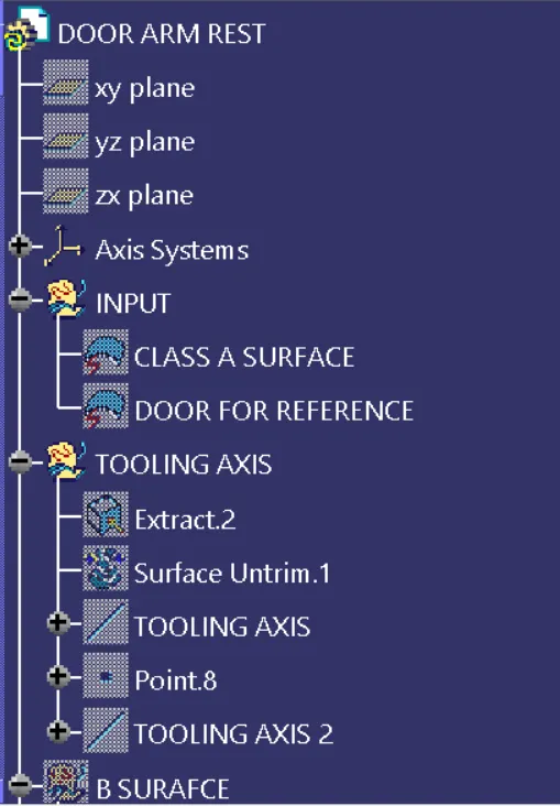
- Simply Create Extract the Base of the component where hole is placed.
- Untrim the extracted Surface.
- Then Using Point Option Create the point on the Untrimmed Surface at the center.
- Now Create the line in Z direction.
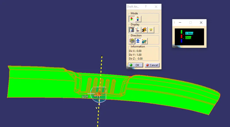
- In the Same Way create the line in Y direction also that which act as side core Tool Axis.
DRAFT ANALYSIS:
- To perform the draft analysis the view parameters are first set to material mode.
- Then Go to insert >analysis>feature draft analysis.
- First, Select the Axis System and drag the axis system to align and coincide with the Tooling Axis and lock the orientation. This Axis system defines the draft direction according to the Tooling Axis.
- Switch on the color scale and set the minimum drafe value. Here it is set to 3 degrees and it will be displayed in green color.
- Now select the running point tool to measure the draft angle at the various locations and then if all surfaces pass the draft analysis switch on the light effect that will show the component has the required draft angle.
- The Bin portion of the arm rest has a negative draftf because the model is not accurate and has some inappropriate surface that creates the problem in the final drafting. To overcome this problem, we will need another Tooling Axis That will clear this region properly in Ejection.
RESULTS:
DRAFT ANALYSIS:
Main Tooling Axis
Side core Tooling Axis
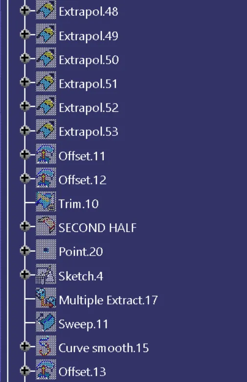
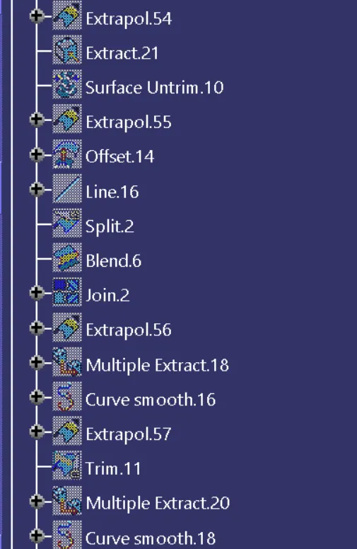
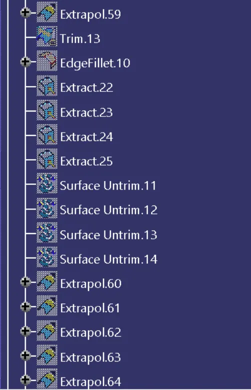
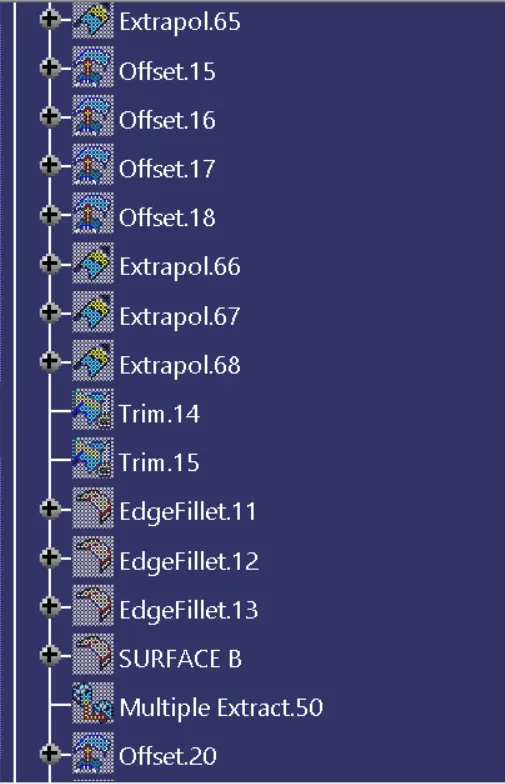
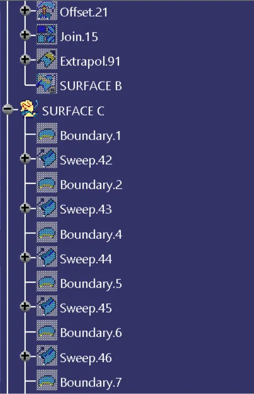
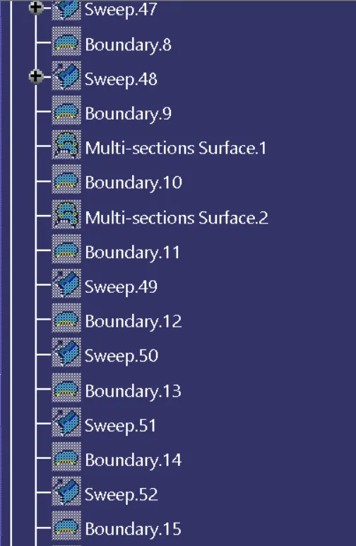
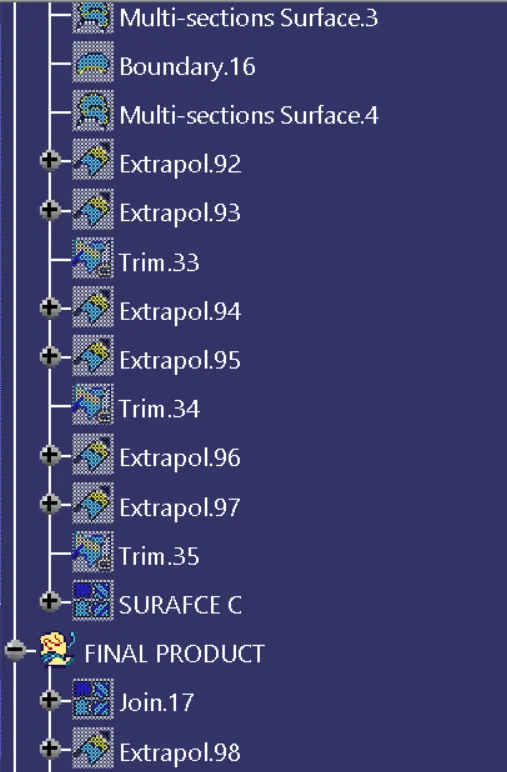
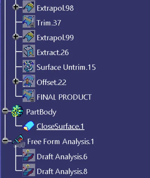
TREE STRUCTURE:
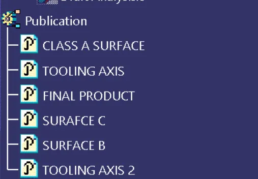
ORIENTATIONS:
ISOMETRIC VIEW:
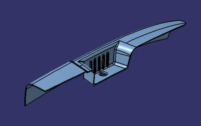
FRONT VIEW:

SIDE VIEW:
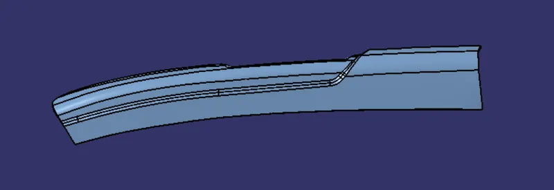
TOP VIEW: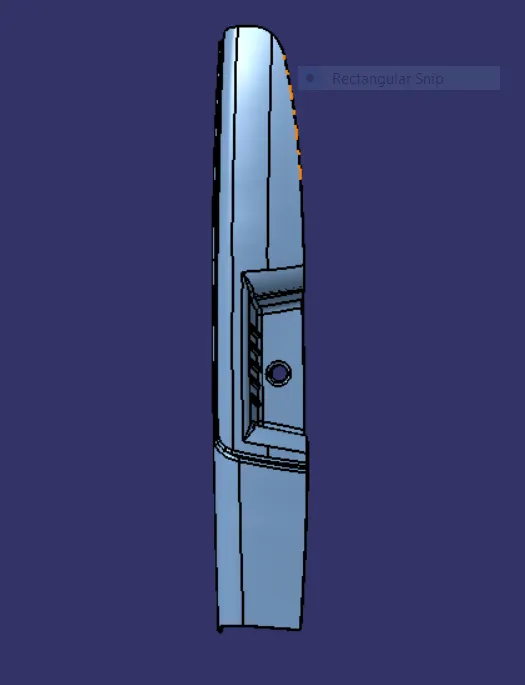
DOOR ARM REST WITH REFERENCE:
CONCLUSION:
Door Arm Rest plastic component using Class A surface have been successfully created and draft analysis also been performed.