Advanced Sheet Metal Design Using NX Cad Challenge_2_Box Assembly
REPORT ON BOX ASSEMBLY
OBJECTIVE:
- Design a sheet metal box using different features tool using NX CAD.
- Create the drawing sheet using NX CAD.
- Understand all the different tools and their Applications.
INTRODUCTION:
Sheet metal is metal formed by an industrial process into thin, flat pieces. sheet metal is one of the fundamental forms used in metalworking. and it can be cut and bent into a variety of shapes. Countless everyday objects are fabricated from sheet metal. Sheet metal is available in flat pieces or coiled strips.
In this project box assembly was created to understand the basics of sheet metal application in Siemens NX.
DESIGN METHODOLOGY:
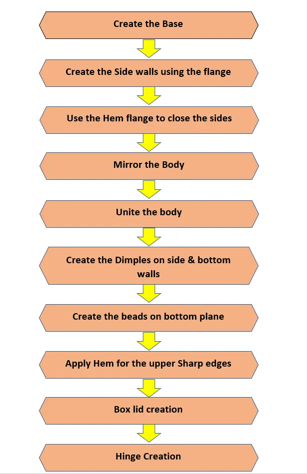
COMMANDS USED:
- Sketch
Base and Initial operation of the sheetmetal.
- Tab
Fill the Sketch by adding the material as Base of the model.
- Flange
Adds flat Flanges on basis of edges at an angle to a planar face.
- Closed corners
Used to closes the corners by extending the bend radius part and flanges.
- Hem Flange
Its Type of the flange which usualy use to lock the flanges.
- Mirror Body
It helps to mirror whole body on other side with reference of planar faces.
- Unite
Combine Two or More bodies into Single one Body.
- Dimple
Its a tool which used to lift the material by taking the reference of contour sketch.
- Bead
Lifts the material along the Contour sketch.
- Mirror Features
Used to mirror the particular Features acros the plane.
- Normal Cutout
Its remove the material that depends on the sketch.
- Bend
Its one of important tool that allows to bend the material as per our requirement.
- Unbend
Used to unbend the adjacent bends material and Flatten Them.
PROCEDURE FOR DESIGNING THE MODEL:
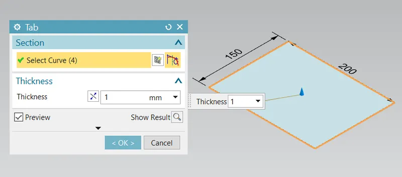
- Create the Rectangular Base Using Tab.
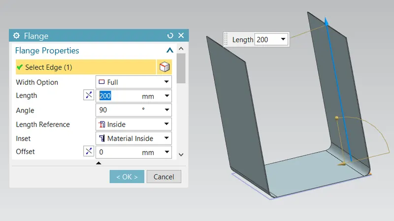
- Create the Box Walls Using Flange Command of lenght 200mm & 70mm.
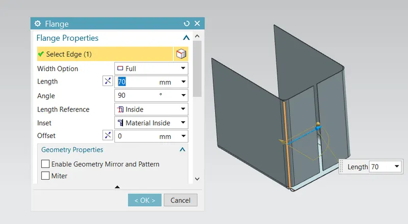
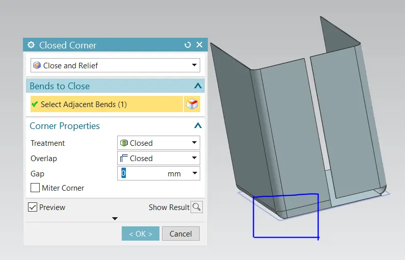
- Corners are closed using the Closed Corner Features.
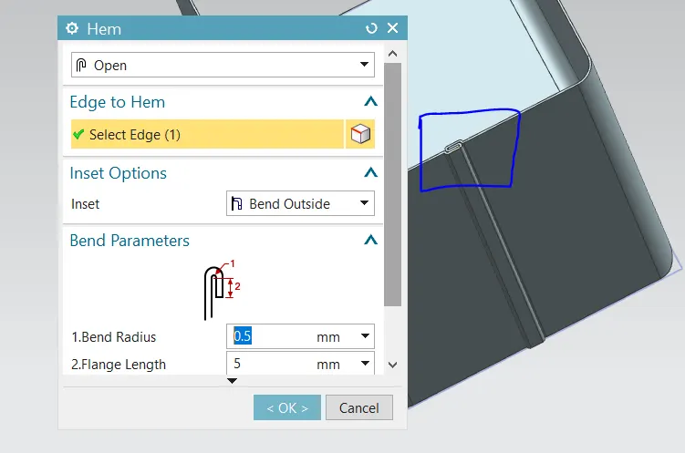
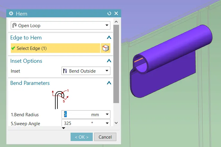
- Hem flanges are used to lock the wall of the Box.
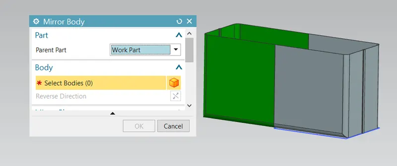
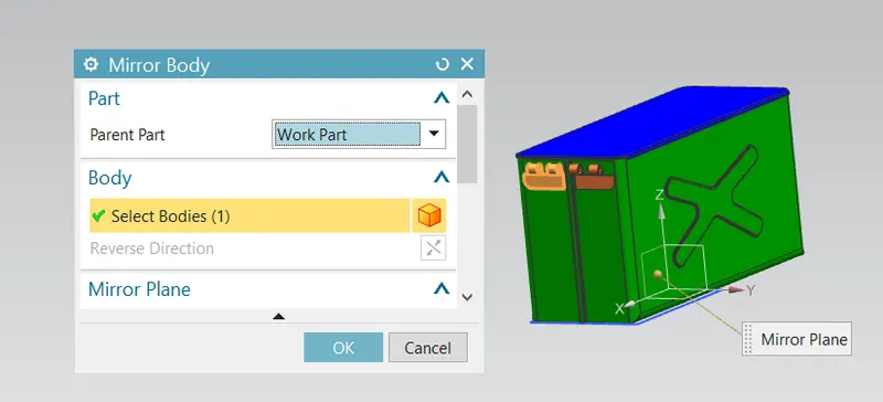
- Mirror the whole body by taking plane as a reference.
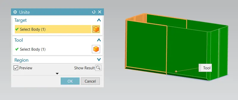
- Combine the two or more bodies into single body using Option Unite.
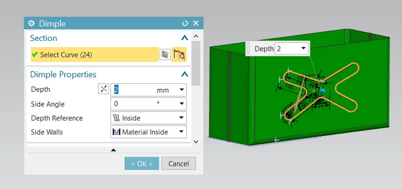
- Dimple is created using the previous Profile.
- Using mirror features the Dimple is mirrored on the Opposite wall.
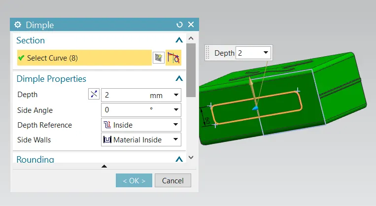
- Another Rectangular Dimple shape is created on the Base of the Tab.
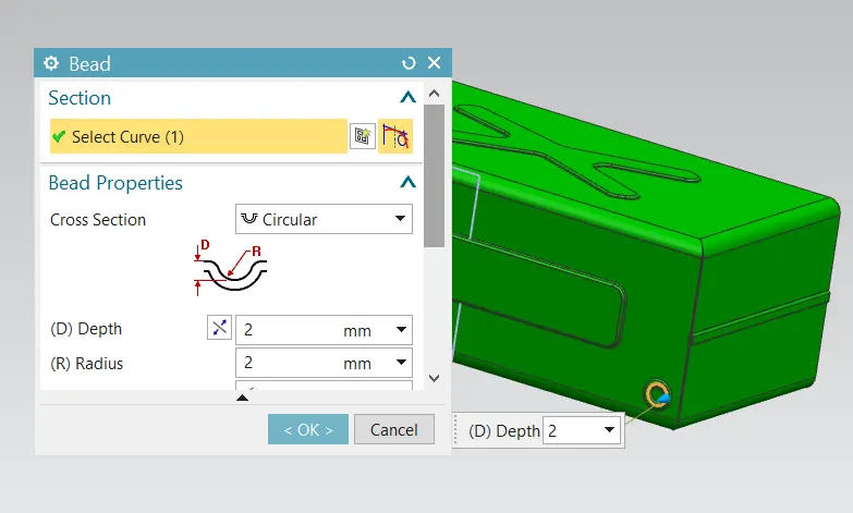
- Bead Lift the material along the Contour of Sketch that stimulates the stamping tool.
- Then mirror the beads.
- A Datum Coordinate system is created at free end of the Tab.
- Lid is created using Tab features on datum plane(203 mm upwards).
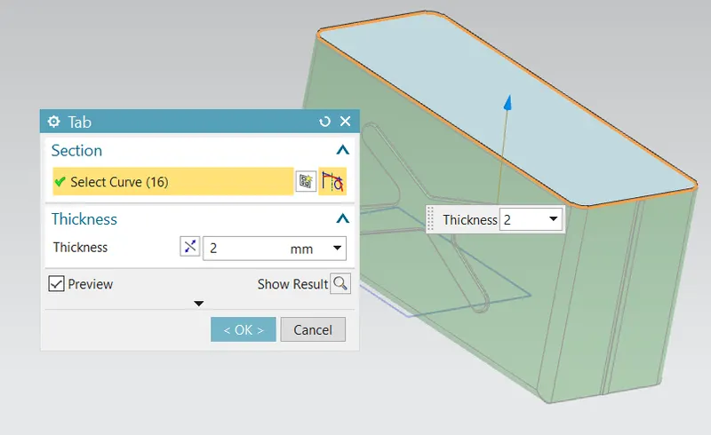
- Flanges are created on all the four sides of the Lid.
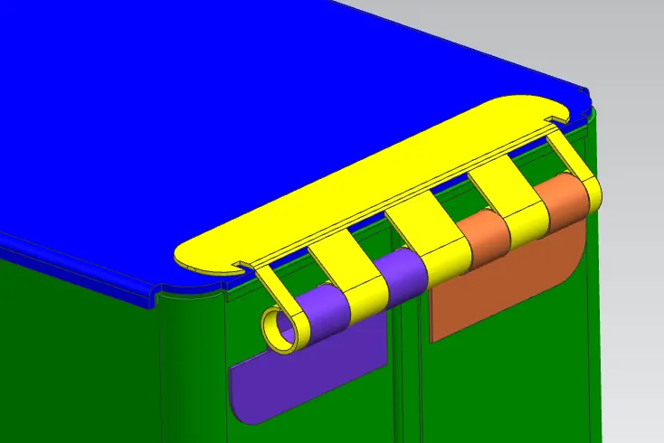
- Using tab, Break Corner, Flange, hem flange, and Normal Cutout Features Hinge is created on the side wall.
- Mirror the same Hinge to adjacent Wall of the Model.
- Similarly Hinge Created on the Lid.
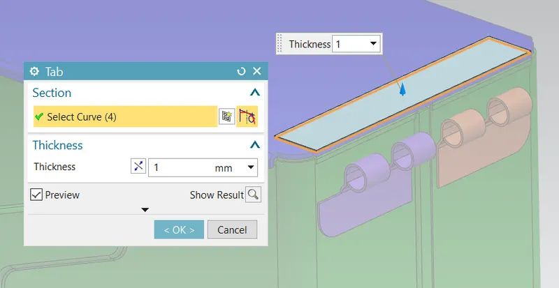
- Create the another flange to connect the below hinges.
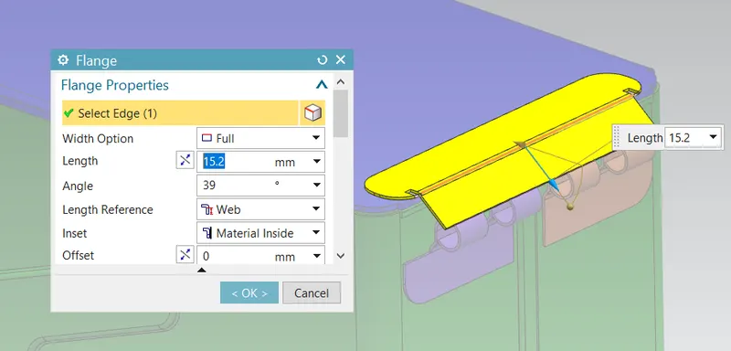
- Apply the hem flanges to edge of the Connecting Flanges.
- Adjust value of the Round flanges with radius and Angles.
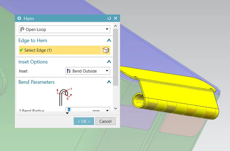
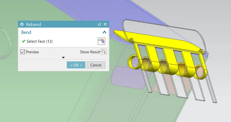
- Unbend the hem Flanges.
- Create the rectangular sketch on it.
- Cut the Unwanted material by using the Normal Cutout Tool.
- Then Rebend the Material.
- Change the appearance of the Model as per our wish.
TOP VIEWS OF MODEL:
FRONT VIEW:
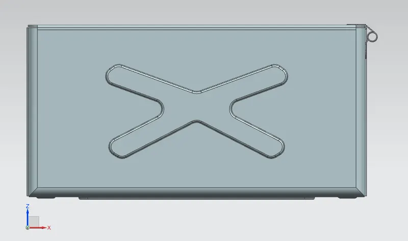
SIDE VIEW:
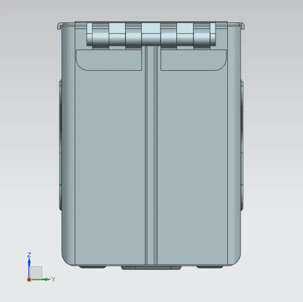
TOP VIEW:

ISOMETRIC VIEW:
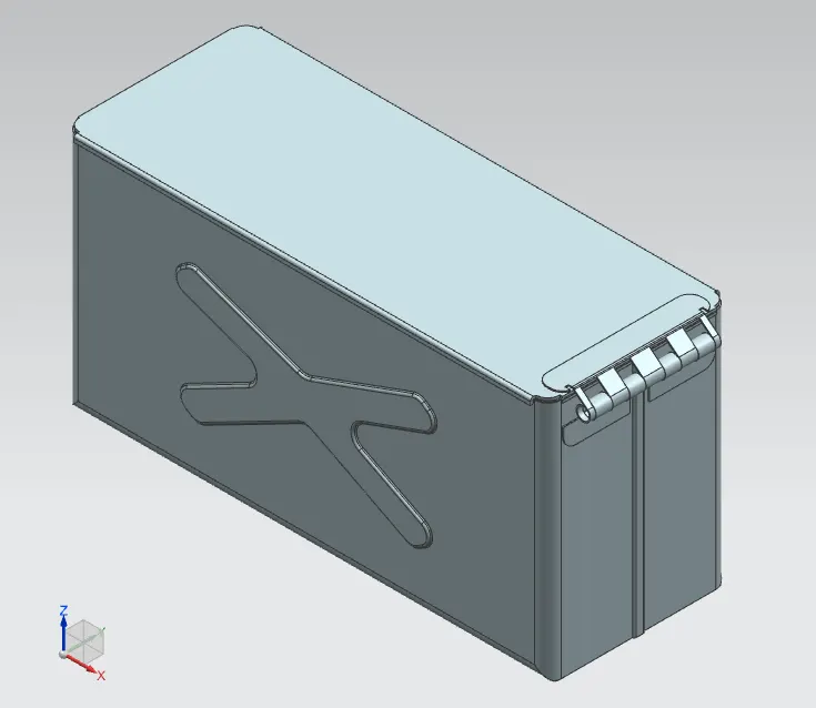
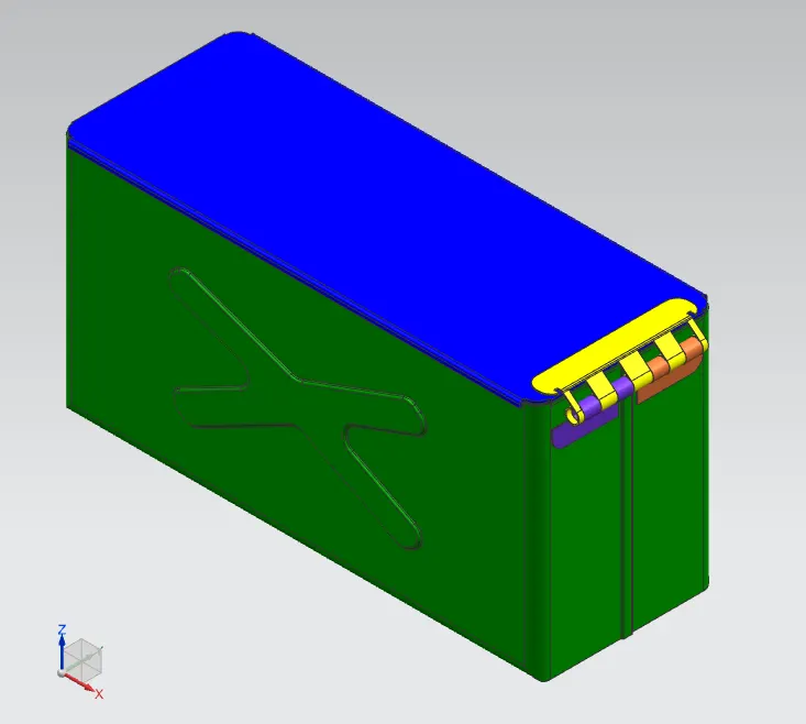
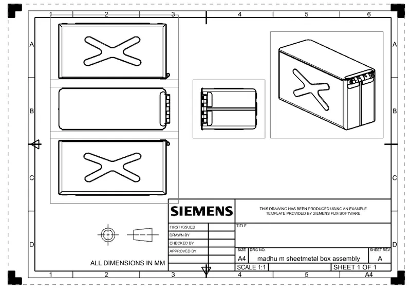
DRAWING SHEET:
CONCLUSION:
The Box assembly was designed Using the Sheet Metal Workbench in NX CAD.