Week 8 - Challenge 1 - Draft Analysis on a Fan Cover
AIM:
Draft analysis on the fan Cover
OBJECTIVE:
The objective of this project is that how to create the Tooling Axis and Draft analysis.
TOOLING AXIS:
Tooling axis defines the mold or core and cavity opening direction. we should create a tooling axis in such a way so that it should cover most of features, holes, geometries and most of the crosssectional area.Here we using Bisecting method to find out tooling direction. we can use any method but the ultimate is to reduce the cost of manufacturing by reducing the complicity in manufacturing the component.
DRAFT ANALYSIS:
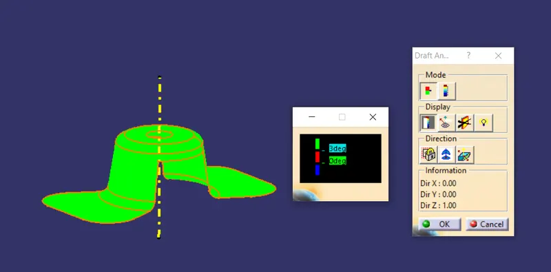
Draft analysis is a method of checking the draft angle on various faces of a part with a particular direction. All plastic components will have a minimum draft of 0.5 to 3 deg. and for Automotive sheet metal parts, the draft will be 7 deg or more.
Draft is used for providing angles or tapers on product features sush as walls, ribs, posts, and bosses that lie parallel to the direction of release from the mold eases part ejection. Draught angles are designed in such a way that they will assist depart rejection. By doing so we have a reduced cycle time and improved productivity.
PROCEDURE:
The procedure is divided into two part first creating the tooling axis then performing the draft analysis.
Creating tooling Axis:
- First finding out the possible tooling direction by visually checking the part and find out the most suitable direction for tooling. Here we choose Z direction as a Tooling Direction.
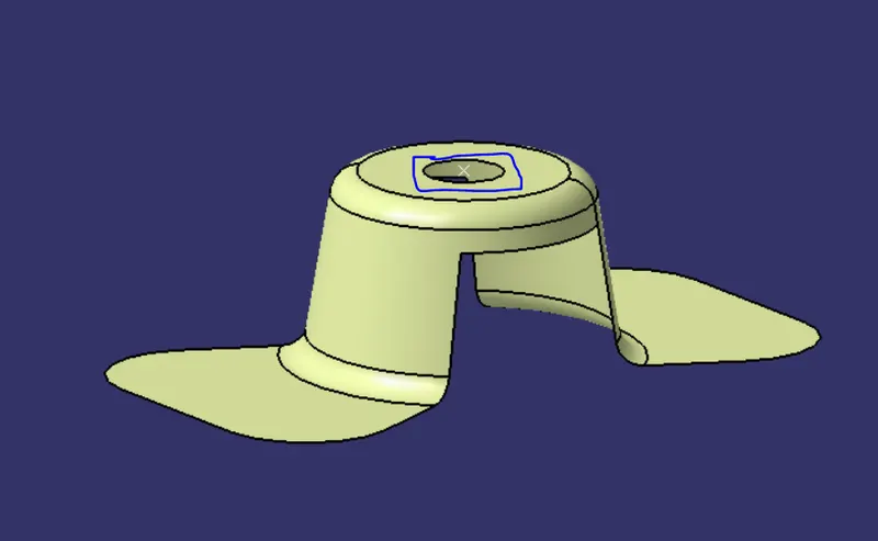
- Then we Create a point on the surface of the part which is ususally near to the center. on this point we put a new axis system.
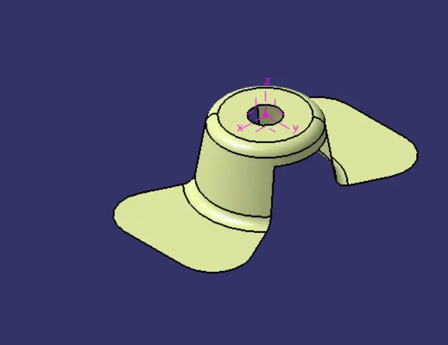
- Then we are finding out the tooling axis in X direction by applying the intersect on the class A Surface.
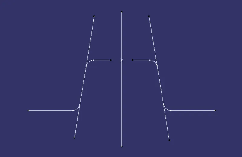
- Then Repeat the same procedure to get the Y Direction with YZ plane as reference. Extending the drafted face using a point-to-point line command. Then using Bisecting line command bisect the both extended lines.
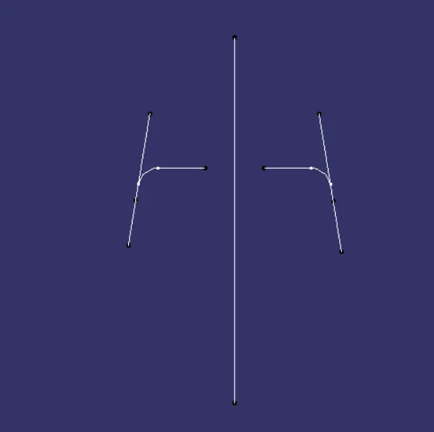
- After Creating the Tooling Axis along X and Y direction bisect both the lines and create the actual tooling Axis.
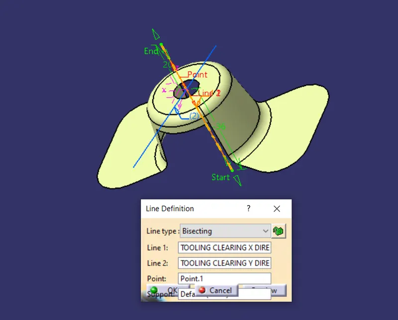
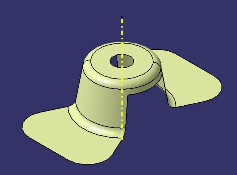
Draft Analysis:
- Open Draft Analysis option form Insert>Analysis>Feature draft analysis.
- Next Position the compass on the tooling axis by dragging the compass from the top right corner of the working area. W axis of the axis system lie on the Tooling Axis.
- Then define the compass by click on the compass icon on the draft analysis window. Then lock the position of the compass by clicking the lock icon.
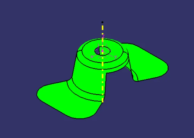
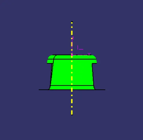
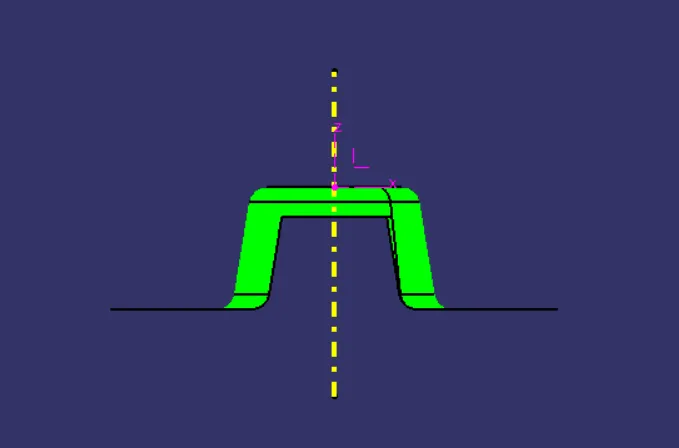
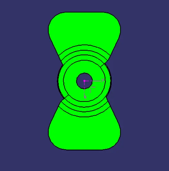
- After that select the surface and the whole surface will show a color range. If it Shows the surface in fully green. which means all faces are having a minium draft angle and its good for manufacturing.If any face is showing blue or red color we have to work on that face to give a good draft.
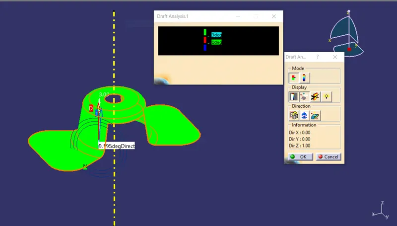
RESULT:
Isometric View:
Front View:
Side View:
Top View:
CONCLUSION:
The Tooling Axis has been created for the given Fan cover model meeting the requirements of the draft angle and performed the draft analysis on the model using CATIA v5.