Photo Realistic Rendering
MODELLING OF AMERICAN CHOPPER IN SOLIDWORKS
INTRODUCTION:
The SOLIDWORKS software is a mechanical design automation application that helps to model 3D parts using 2D sketch.it has option to specify the material that which define the part. it also has the option to rendering of the model using solidworks visualize and photoview 360 to make the chopper more natural and realistic. In this project we learnt about how to design of american chopper parts and assembling them and rendering final chopper using photoview360 after the assembly.
OBJECTIVE:
- To create all individual parts of american chopper using solidworks software.
- To assemble all the individual parts into a chopper.
- To know the features of extrude boss/cut, revolve boss/cut, extrude cut etc.
- To know the application of decals, scene setup, lights, camera, rendering option etc.
- To create photorealistic model and render the model using photoview 360.
STANDARD FEATURES USED FOR MODELLING THE AMERICAN CHOPPER
- EXTRUDED BASE:
The extrude adds material to a part by building upon the base.
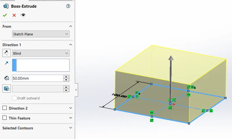
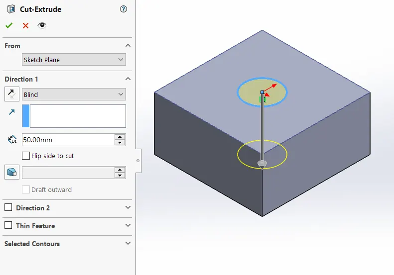
b.EXTRUDED CUT:
The cut-extrude tool is similar to an extrude feature, except that it removes material from the model instead of adding material.
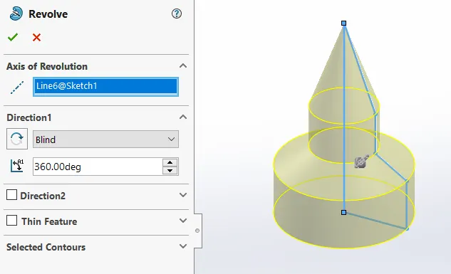
c.REVOLVE:
The Revolve tool revolves a sketch profile around a centerline at a specified angle.
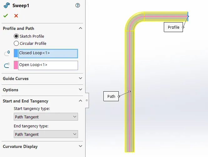
d.SWEEP:
The Sweep tool to make the hollow shape by projecting the profile along the path.
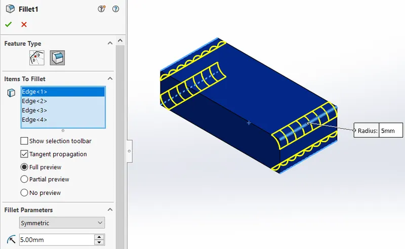
e.FILLET:
The fillet is a tool used to round an edge, vertex or face on both inside and outside of a 2D or 3D model.
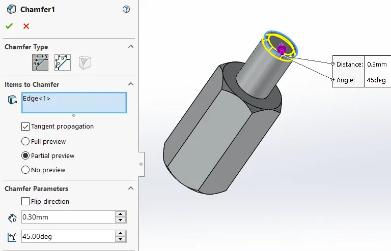
f.CHAMFER:
A Chamfer is used to remove a sharp edge by creating a sloped edge.
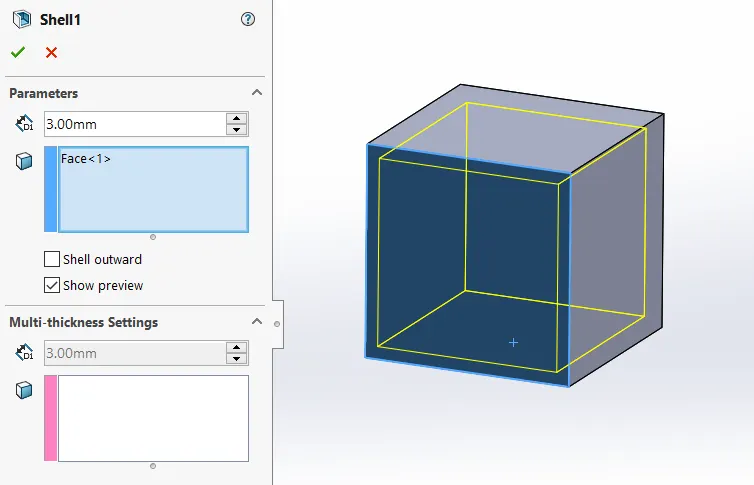
g.SHELL:
The Shell tool hollows out a part, leaves open the faces you select, and creates thin-walled features on the remaining faces.
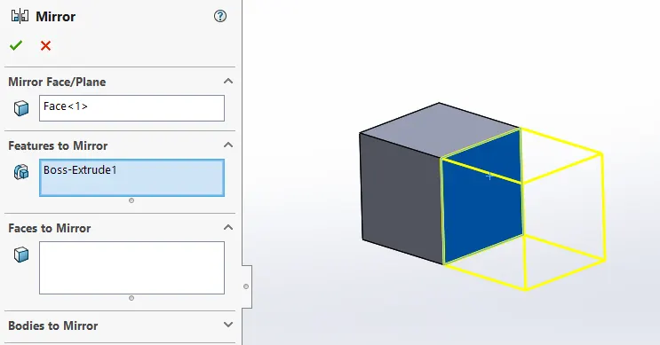
h.MIRROR:
The Mirror tool used to copy the same object about a reference line or plane or face.
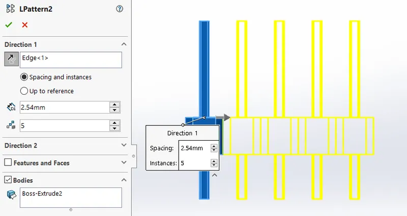
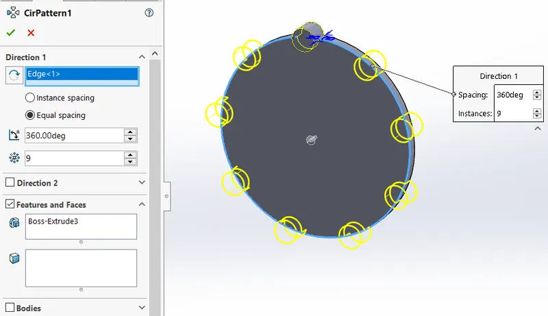
i.LINEAR AND CIRCULAR PATTERN:
Linear pattern drives the features in a linear direction with equal spacing.
Circular pattern drives the featurs in a circular direction about an axis with equal spacing.
j.PROJECTED CURVES:
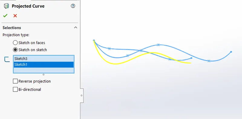
Projected curve create a 3D curve that represents the intersection of two extruded surfaces generated by creating sketches on two intersecting planes.
k.MATES:
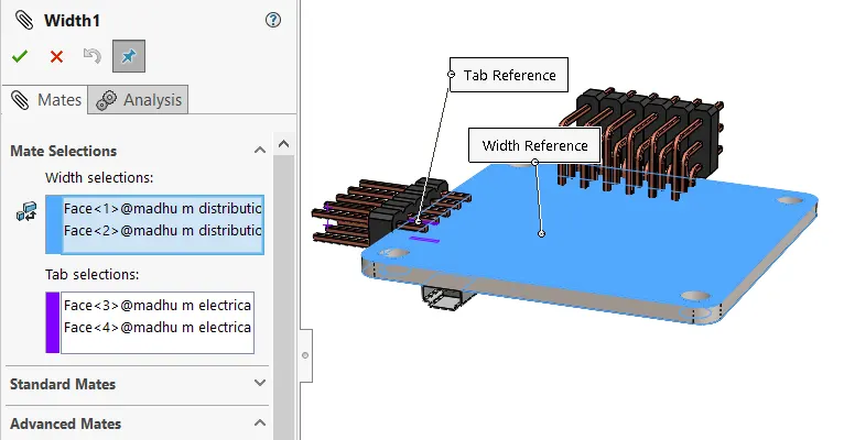
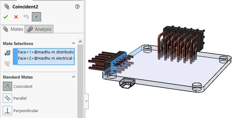
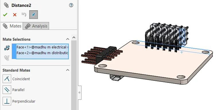
Mates position the parts in an assembly precisely with respect each other. here we used coincident, concentric, distance, width mates etc.
DESIGN METHODOLOGY/APPROACH:
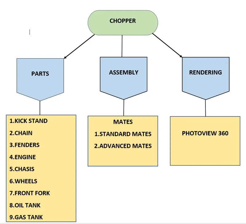
PARTS:
1. KICK STAND
Kick stand is a device which helps chopper to rest on floor.
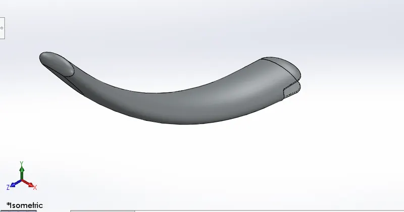
Features used to create kick stand part:
- Sketch
- Loft
- Dome
- Extrude boss
- Extrude cut
- Fillet
- Split
Sketch:
The Sketch is a base of 3D representation of model. these are called as entities in solidworks.
e.g: line, rectangle, spline, circle etc.
Loft:
Loft features blend multiple profiles and transition them into smooth shapes between profiles specially for critical shapes.
Dome:
A Dome is a hollow half of a sphere.
Extrude boss:
It convert 2D Sketch into 3D Sketch.
Extrude cut:
It remove the material from the part.
Fillet:
Fillet/Round creates a rounded internal or external face on the part.
Split:
It divides a selected face into multiple seperate faces.
PROCEDURE:
- Open solidworks select new part.
- Select the mid/right plane and start the Sketch.
- Then select front plane draw the spline line as per the diamension.
- Create new plane with the reference of spline.
- Create ellipse on new plane.
- Loft the ellipse profile along the spline.
- Apply the extrude cut to remove the unwanted material.
- Fill the cut part with boss extrude.
- Apply dome at both ends.
- Apply fillet to edge.
- Finally save the part with the name of "kick stand"
2.CHAIN
Chain is a transmission device which is used for transmission of mechanical power between engine and rear wheel.
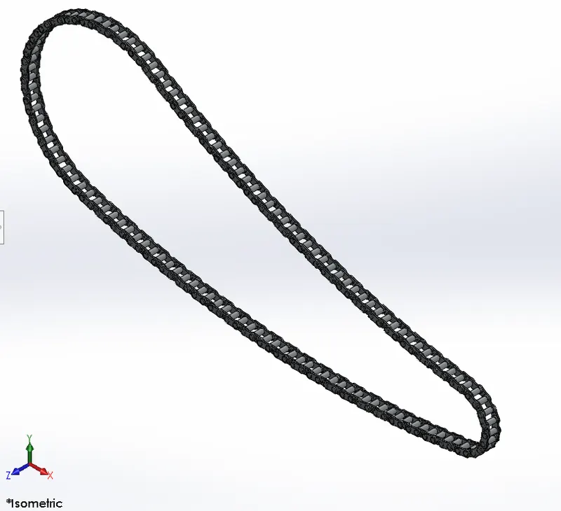
Features used to create chain part:
- Sketch
- Trim
- Fillet
- Blocks
- Extrude
- Patterns
Trim:
Trim eliminate the sketch entities which is outside of two bounding entities.
Patterns:
The Curve Driven Pattern tool allows to create pattern along a planar or 3D curve.
Blocks:
A block is a light sketch of whole part composition before any details are done regarding whole part.
and we can save it and use it whenever its needs.
PROCEDURE:
- Select the plane start sketch That path of the chain with the helps of arc and lines.
- Create the 2 blocks as per the requirement and save it.
- Drag the blocks on the path and placed it using coincident and concentric relations.
- Apply the curve driven pattern features along the curve.
- Again drag blocks repeat above procedure till complete the path with blocks.
- Finally mirror the all the pins and boss extrude.
- Now save the part by assigning the chrome metal.
3.FRONT & REAR FENDERS
Front & Rear fenders(mudguards) both are same and these are used to protect the rider feet and ankles from debris & foreign particles.
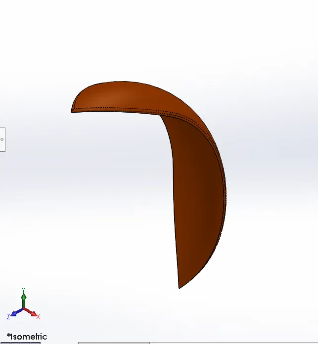
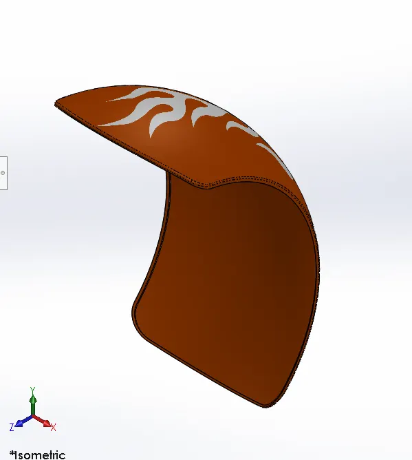
Features used to create Front/Rear Fenders part:
- Sketch
- Offset entities
- Trim entities
- Revolve
- Dynamic mirror
- Split
- Appearance
Revolve:
Used to revolve a 2D sketch in a circular pattern(360 degree) about an axis and centerline.
Dynamic mirror:
It is one of the valuable features which helps to mirror the entities that presketched Sketch entity.
4.ENGINE
Engine is the main part of the bike which provides the power to the motion by generating the mechanical energy from chemical energy.
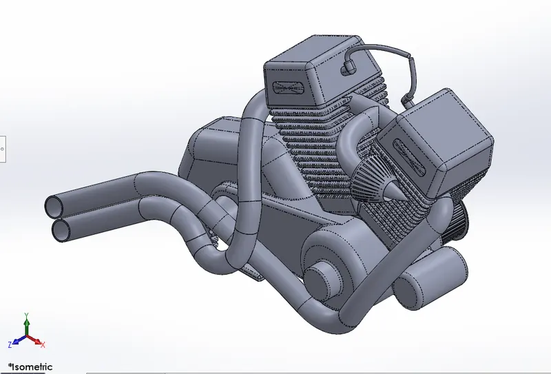
Features used to create Engine part:
- Sketch
- Revole
- Boss extrude
- Extrude cut
- Dome
- Fillet
- Projected curve
- Composite curve
- Sweep
- Circular pattern
- Mirror
Projected curve:
Represents the intersection of two sketches on intersecting planes.
Composite curve:
It forms single curve by merging two individual curves.
5.CHASSIS
A chassis is the skeletal framework of a vehicle on which most of the mechanical parts like tires,brakes,axle assemblies and the engine are fastened.
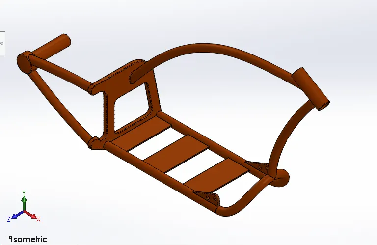
Features used to create Chassis part:
- Sketch
- Offset
- Convert entities
- Project curve
- Trim
- Sweep
- Split
- Revolve
- Cut extrude
- Fillet
- Combine
Offset entities:
Offset entities takes a copy of existing geometry & copies it an offset. Instead of recreating geometry.
Convert entities:
The convert entities tool allows to make a copied projection of a given sketch.
Combine:
The combine function allows to add two bodies together.
6.WHEELS
Wheels allow heavy objects to be moved easily transportation while supporting the load.
Both front & rear wheels have the same designing steps but differ in the Size.
a. FRONT WHEEL
Front wheel has a larger diameter to take & manage impact better than the rear. The front tire experiences the greatest forces during braking.
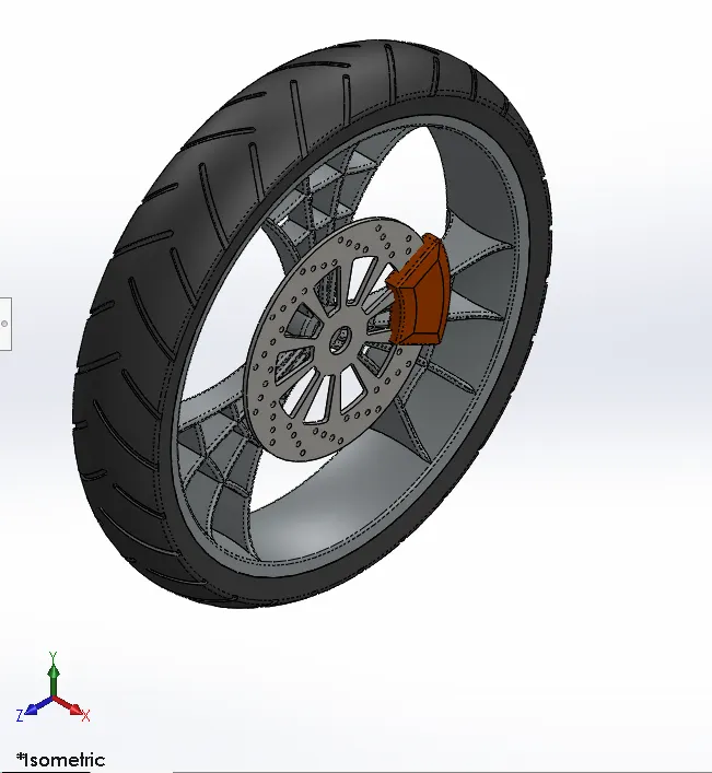
b.REAR WHEEL
The rear wheel is primarily used for acceleration and propelling the motorcycle forward. It is wider than the front wheel to improve the stability of the bike. The chain is connected between engine & rear wheel.
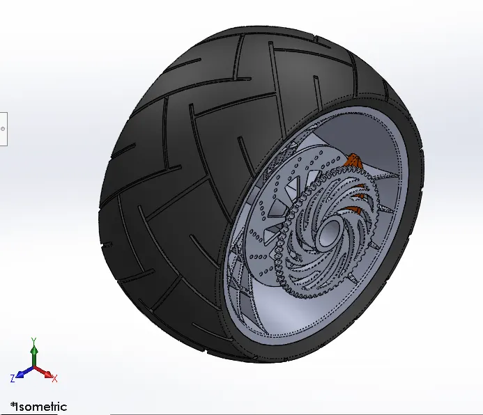
Features used to create Front/Rear wheel part:
- Sketch
- Trim
- Revolve
- Sketch fillet
- Planes
- Revolve cut
- Linear pattern
- Chamfer
- Fillet
- Circular pattern
- Extrude cut
Circular pattern:
To create multiple instances of one or more features that can space uniformaly around an axis (circular shape).
Linear pattern:
To create multiple instances of one or more features that can space uniformly along one or two linear paths( straight path).
7.FRONT FORK
A motorcycle fork connects a motorcycles front wheel and axle to its frame.The most common form of front suspension for a modern motorcycle is the telescopic fork.
This part consists of front fork, handle bar, head lights, break, clutch levers, wires and handle grips.
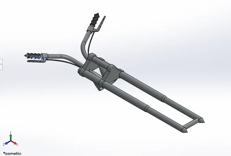
Features used to create Front fork part:
- Sketch
- Trim
- Extrude boss
- Revolve
- Mirror
- Combine
- Projected curve
- Split
- Sweep
Mirror:
Mirroring is another way that SolidWorks can Create a Copy of an existing object.
Sweep:
Sweep is a tool that creates a solid, a cut or a surface features by moving a profile along the path.
8. OIL TANK
It is filled with fuel which is require to generate energy to the chopper. it is hollow device where thickness is 3mm in this case.
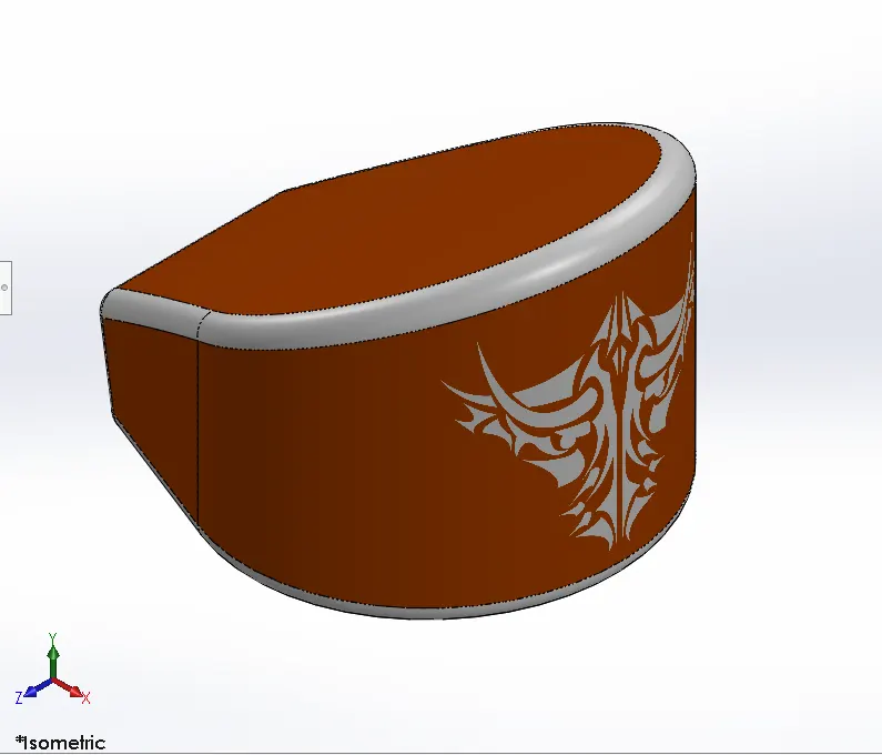
Features used to create Oil tank part:
- Sketch
- Extrude boss
- Shell
- Fillet
- Combine
Shell:
The shell feature hollows out the inside of the solid leaving a shell of a specified wall.
Combine:
It is option where we combine more than two bodies manually like add, substract etc..
9. GAS TANK
Gas tank is stores gasoline and provides whenever engine needs to generate the energy.
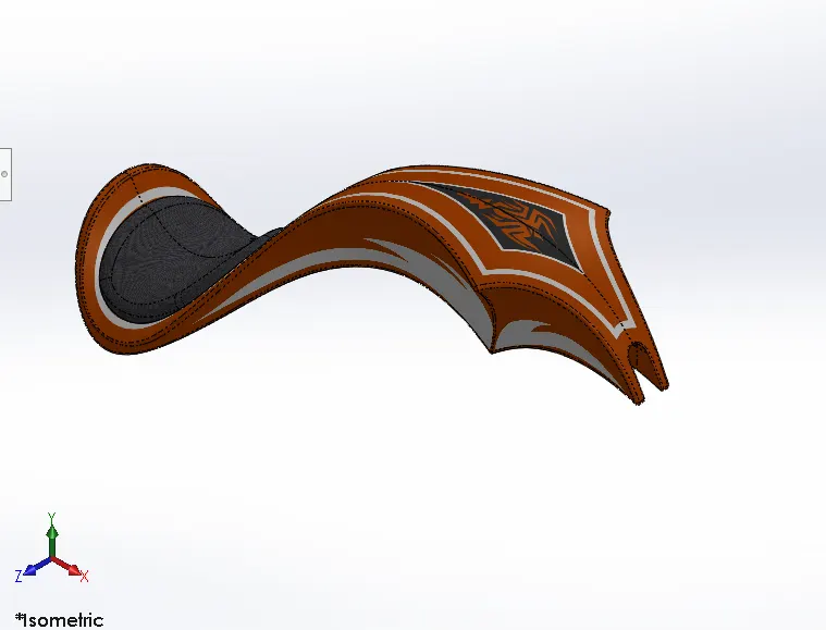
Features used to create Gas tank part:
- Sketch
- Trim
- Projected curve
- Sweep surface
- Fill surface
- Surface knit
- Surface trim
- Loft surface
- Fillet
Sweep surface:
Sweep surface are surfaces that are generated from a section curve positioned along a path.
Fill surface:
The filled surface features constructs a surface patch with any number of sides within boundary defined by existing model edges.
Surface trim:
Used to cut away material from surface.
Provides 2 mode
- Standard mode
- mutual mode
Surface knit:
Used to combine two or more faces and surfaces into one.
Loft surface:
Loft surfaces are surfaces generated by multiple 3D Curves or existing edges creating a smooth tangency between the selected curves.
10. PEDAL
Pedal is part of bike on which the foot rest is attached.rider put is leg on pedal for comfort purpose during the riding.
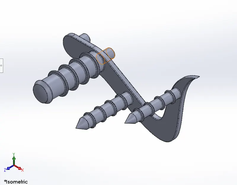
Features used to create pedal part:
- Sketch
- Fillet
- Linear patter
- Dome
- Chamfer
- Extrude
Linear pattern:
To create multiple instances of one or more features along one or two linear paths.
Dome:
Dome is option which forms hollow half of a sphere on selected area.
11. TRANSMISSION BELT
It is medium through which power is activate between engine & gear box.
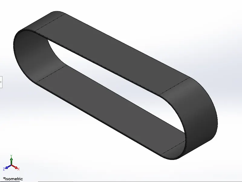
Features used to create transmission belt:
- Sketch
- Fillet
- Offset
- Extrude boss
- Appearance
Offset entities:
An offset entities relation is created between the new sketch entity and the selected entity.
It forms the replica of sketch in outwards or inwards of sketch that what we selected as a reference.
PROCEDURE:
- Open solid work select new part.
- Select front draw the sketch as per requirement.
- After completing sketch apply offset option to create duplicate of same sketch in inwards direction.
- Now apply extrude features which converts 2D Sketch to 3D model.
- Apply fillet.
- Save the model by assigning the rubber features.
ASSEMBLY:
An assembly is a collection of related parts.
The components in an assembly are defined in relation to each other using assembly mates.
There are two basic methods:
- Bottom up design
Here we first design the model individually then insert into assembly environment.
Here we modify the part individual and that changes seen in the assemly.
- Top down design
Here parts, size, plane, locations can be designed in assembly environment.
Here less rework is needed when design needs change.
HERE WE USE BOTTOM UP DESIGN
Features used to create Assembly:
- Mates
Mates:
Mates create geometric relationships between assembly components.
when we apply the mates that define the allowable directions of linear or rotational motion of the components.
- Coincident mate: A Coincident mate positions two vertices/faces/edges for contact.
- Concentric mate: Selected items can share the same center point.
- Distance mate: Selected items define specified distance between them.
- Angle mate:Locates selected items at specified angle to each other.
- Width mate:A width mate constrains a tab between two planar faces.
PROCEDURE:
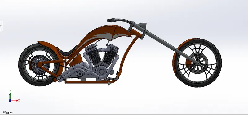
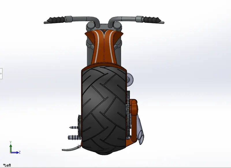
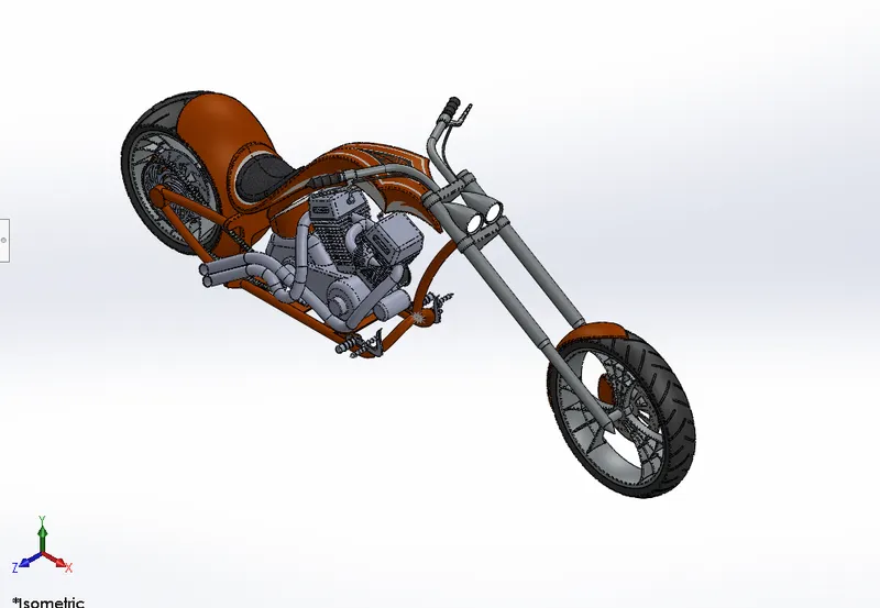
- Open solidworks & select the new assembly option.
- Insert the existing chassis file click k it will fixed automatically.
- For remaining parts insert the file and use the distance, concentric, width and coincident mates.
RENDERING:
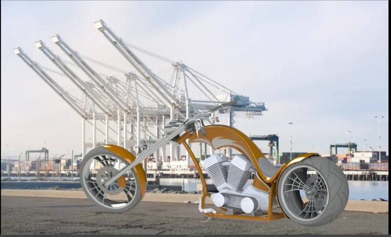
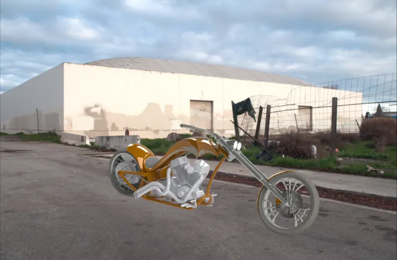
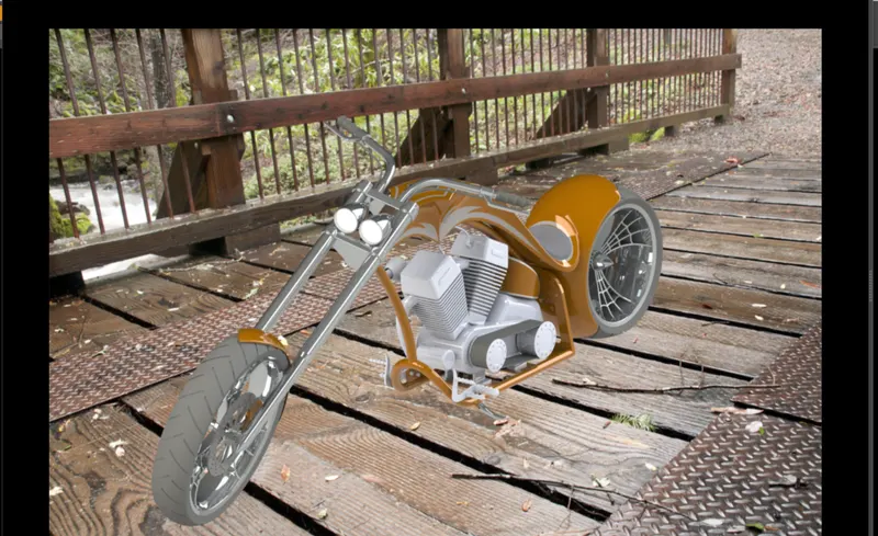
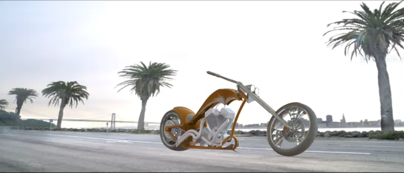
Rendering is the process of creating realistic images of the photorealistic model with the environment.
There are two applications to get the rendering images.
- PhotoView 360
- Solidworks Visualize
HERE I USED PHOTOVIEW 360
PhotoView 360 produces photo realistic rendered image of models.
PROCEDURE:
- Click Tools>Add-In & add in photiview 360.
- Start a preview in the geaphics area.
- Edit appearances, the scene and decals,
- Edit lights.
- Edit PhotoView Options.
- Perform a final render.
CONCLUSION:
- Modelled the all parts using solidworks.
- assembled all parts in assembly environment.
- By using Photoview 360 rendered the assemly of the chopper.
- Got the advanced knowledge of solidworks.
- Understanding of how and why when modelling.