Week 8 - Challenge 4 - Coin Holder Design
AIM:
To perform draft analysis and make a solid model from the given class A input.
OBJECTIVE:
- Create the Coin Holder Plastic component through the given Class-A surface and provide the Thickness of 2.5 mm.
- Performing draft analysis to verify the creation of the Tooling Axis and C Class surface.
Tooling Axis:
Tooling Axis is the direction in which core and cavity open and close without making any default.
Draft analysis:
Draft analysis is a process in which we measure the angle of the side walls of the component with different colour mode which may cause problem in the manufacturing.
CREATING THE MAIN TOOLING AXIS:
- First extract the base surface & Create point on that surface. Insert axis system at that point. Take intersection of class A surface with the XZ plane of axis system. Create two lines along the verticle faces. create Two lines along the verticle faces. Create line using bisecting Method. or
- Create an axis system using the surface at the bottom and use point to create the axis system.
- Intersect the YZ plane with respect to the class a surface walls.
- Create a line in ZX plane at 6 degree with respected to intersection.
- Hide the class A surface and create point to point lines on the suspected drafts.
- Create a bisecting line with the two lines and point to create a Tooling Axis.
- The Tooling axis is created for the component.
PERFORMING THE DRAFT ANALYSIS:
- Before going to draft analysis go to customized view parameter check material and then click ok.
- Now for draft analysis go to insert > analysis> feature draft analysis.
- Use the compass to define the draft direction.
- In the colour scale change the draft angle to 3 degree.
- The component changes to green in indication of passing draft angle.
- Use running point to check the angle on the component.
- The draft analysis is complete.
RESULTS:
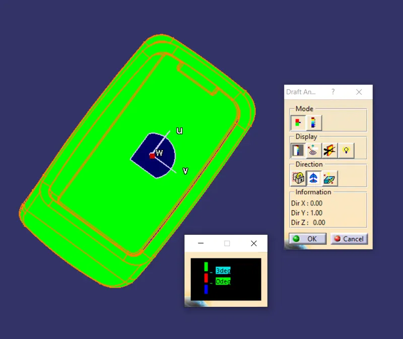
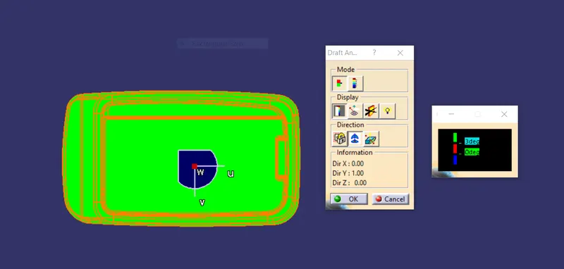
A:Here we consider the main tooling axis to perform the Draft analysis and we consider the minimum 3 angle as a draft angle which indicates free moving of core and cavity in the main Tooling direction without making any unpleasant surface or leads to the machines breaks. The below draft analysis is passed the draft analysis conditions to move on the further manufacturing process.
CLASS A SURFACE:
PLASTIC COMPONENT:
B:
As we observed these Blue surfaces are equal to zero degrees. If the Surfaces are at 0 degrees the plastic part won't eject at the end due to contraction after the cooling process.
- To tackle this problem we should create the secondary and tertiary side core tooling axis to overcome this problem.
- Here walls are at 90 degree so that as a design engineering we should ask the person who can create the surface A. Create a Class A surface with little bit of draft angle then only we can remove these undercut issues.
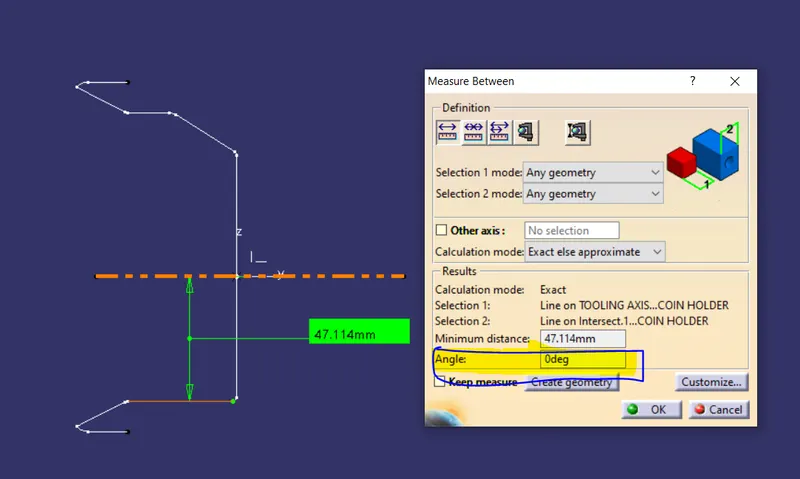
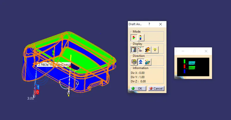
As we observed the side walls are in blue that means these walls are at 90 degree or draft angle is zero so these kind of the walls are create the unpleasant surface also leads to the damage of the core and cavity during the production so that for removing this complexity we need to modify these walls with minimum draft angle in Surface A.
ORIENTATIONS:
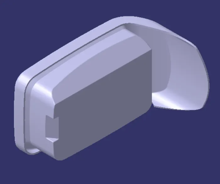
ISOMETRIC VIEW:
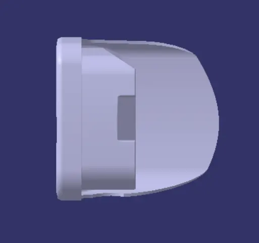
FRONT VIEW:
SIDE VIEW:
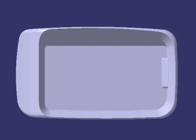
TOP VIEW:
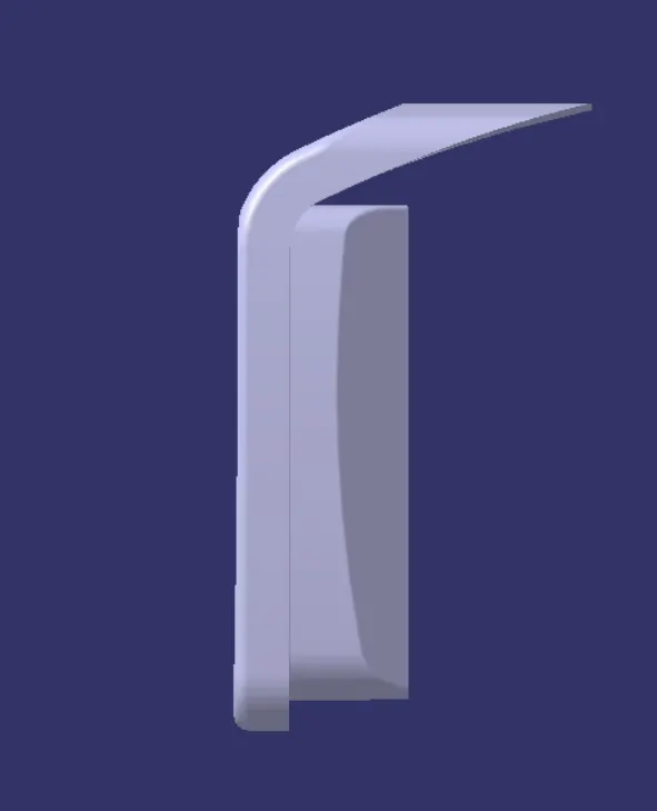
CONCLUSION:Here i created coin holder with thickness 2.5 mm and Perform the draft analysis for both Class A Surface and Plastic Component.