Roof challenge
AIM:
To Design Roof, Front roof rail, Rear Roof Rail, Bow Roofs, and reinforcement roof centre by following the Master section with the design parameter for the given class A surface.
INTRODUCTION:
An automobile roof or car top is the portion of an automobile that sits above the passenger compartment, protecting the vehicle occupants from sun, wind, rain, and other external elements.
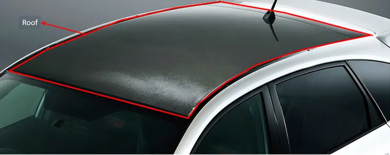
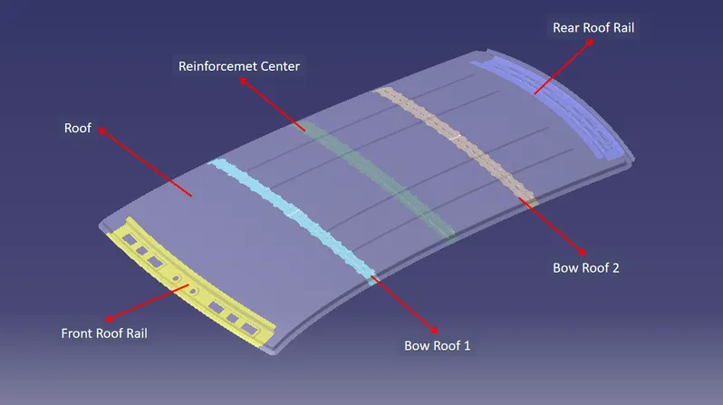
Roof is consisting of the following parts shown in the fig 0.1A
- Roof: An automobile roof or car top is the portion of an automobile that sits above the passenger compartment, protecting the vehicle occupants from sun, wind, rain, and other external elements.
- Front Roof Rail: Front roof rail is the additional commodity which acts as reinforcement also it has certain features in it which will be supporting bracket maplamp and room lamp.
- Rear Roof Rail: Rear roof rail is mainly supporting the roof. And also the back door hinges in order to make opening and closing.
- Reinforcement center: It is the main supporting member of the roof where it helps to absorb energy at the time of side crash. Also it acts as a bow roof for small cars.
- Bow Roofs: This is the roof supporting rails, which provides additional stiffness, designed based on Heat Distortion Criteria and Snow load Condition.
DESIGN PROCEDURE:
1. Import the given input fie of class A styling Roof surface from the file location.
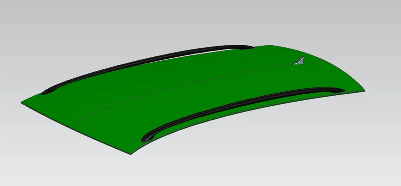
2. Roof Design:
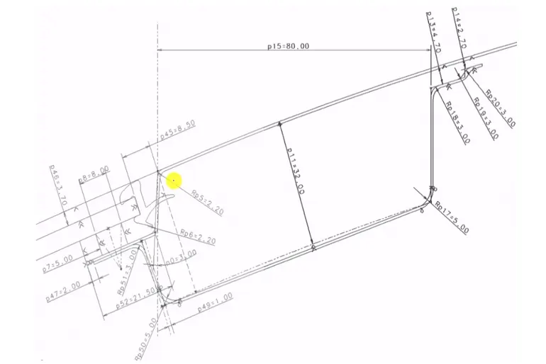
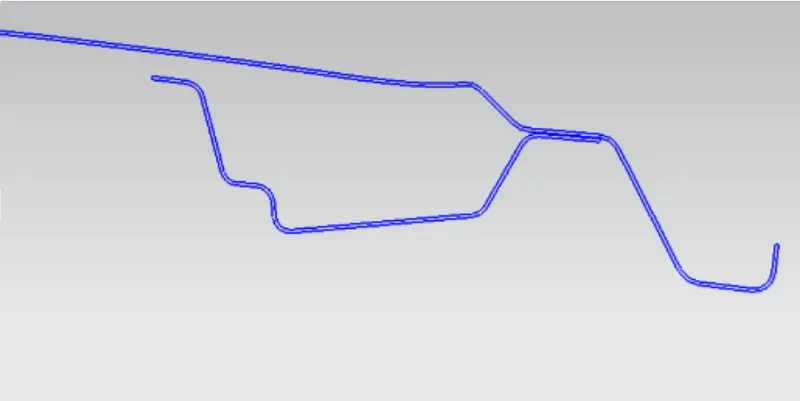
Given surface is A class and we have to Design Roof using the given class A with the help of the Given master section shown below.
Master section is developed based on the previous car model and Head Roof clearance 85mm, There are two master sections on it for front and other one is for rear side.
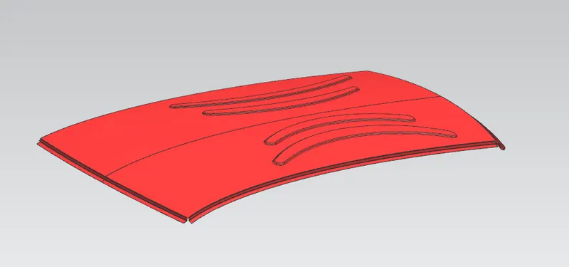
From the class A roof is developed by using mastersection, shown below:
Detailed sections of the corners devoloped in the above roof is shown below:
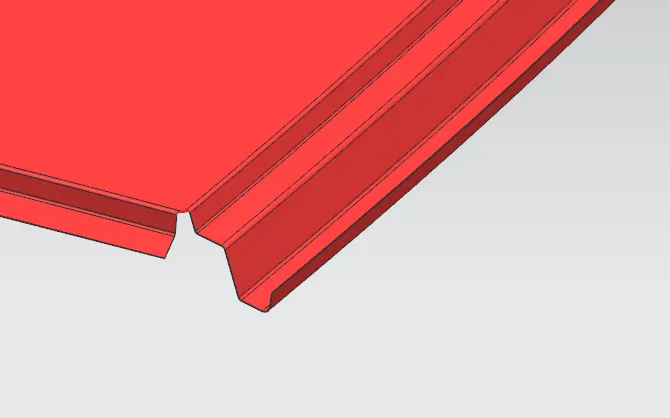
Onlt half portion of the roof has to be devoloped and other half can be mirrored as the part is symmetrical and Sew it.
The thickness of the roof is given as 0.75mm
2. Front and Rear Roof rail Design: We are using the same master section which is used on the roof. This master section is developed based on Visibility criteria and head roof clearance.
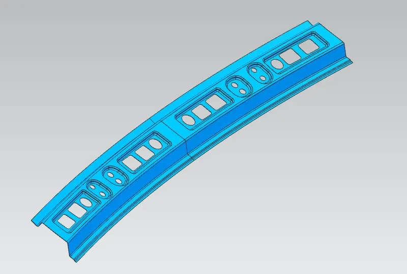
From the class A, front roof rail is developed by using mastersection which is shown below:
From the class A, rear roof rail is developed by using mastersection which is shown below:
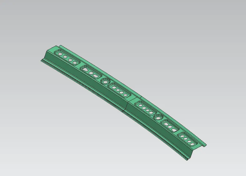
Embosses has been created inorder to increase the structural stability of the roof rails with various pockets for the material reduction.
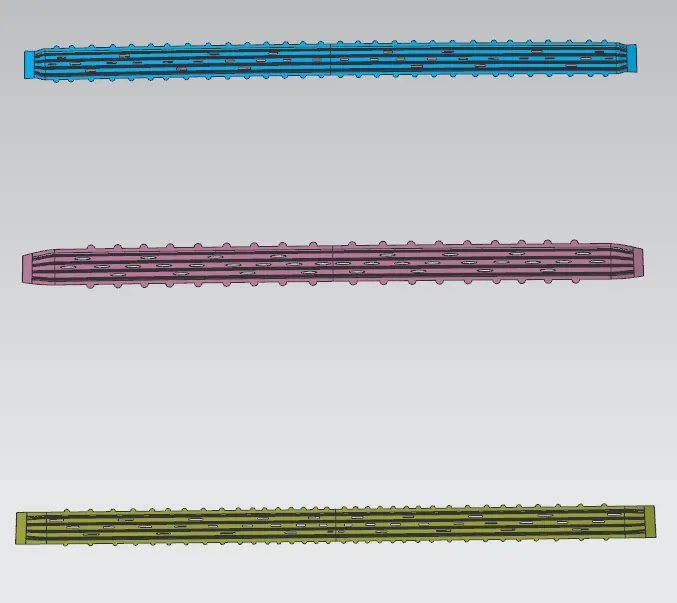
Similarly Design of the bow roof rails and Reinforcement center Shown in the below figure:
4. BOW ROOF PREDICTION FORMULA:
A: Heat Distortion Criteria
W = [1.73 x 10^(-3) x L] + [1.85 x 10^(-8) x (R^2)/t] + [ 1.10x10^(-3) x l] - 2.68
Judgement Condition : OK< 2.7> 3.1
Where
L = Roof Length in X-Direction[mm](Roof dimension in 0-Y)
R = Roof curvature
R = 2(Rx*Ry)/(Rx+Ry)
Rx = X curvature
Ry = Y curvature
t = Roof plate thickness [mm]
l = Bow Roof Span [mm]
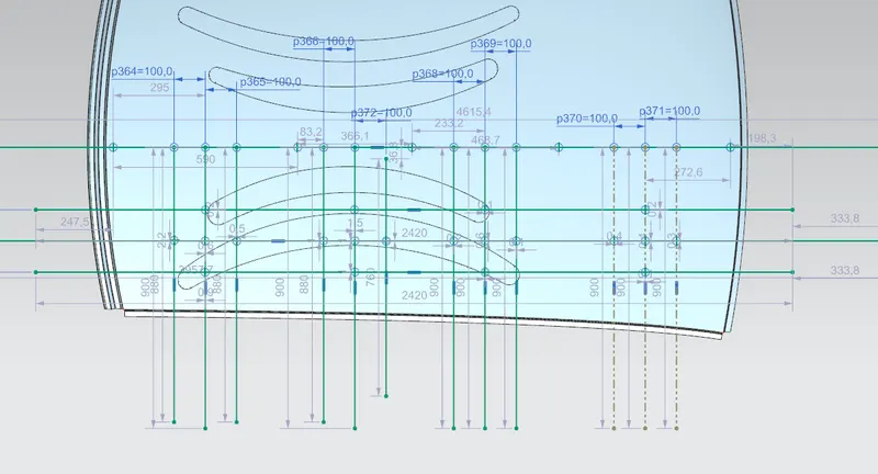
From the Model we have all the values shown
Calculations are done and tabulated in the table :

B. Snow load Prediction formula
Qr = [Iy x t2] / [α x s x [(Rx + Ry)/2]2 x 10-8]
Where
α = My x Lx2 x 10-12 , My = Y(Ly-Y)
Judgement condition = Qr ≥ 3.1
250 ≤ s ≤ 380
t = Roof plate thickness [mm]
Ly = Distance between the front and rear roof Rails on the Vehicle along with 0Y[mm] Length of Roof panel with the center point between Roof rail Front /Rear as the reference point of the front and the rear.
Lx = Distance between the Left and Right end of the roof on the Roof BOW [mm] Width of the roof panel exposed on the surface.
Y = Distance front Front Roof Rail to Roof BOW[mm]
s = Distance for which Roof BOW bears divided load [mm]
s = L1/2 + L2/2
Iy = Geometrical moment of inertia of Roof BOW (Y cross-section )[mm4]
Rx = Lateral direction curvature radius of roof panel Y cross-section on Roof BOW [mm] Roof panel curvature Radius of the Length Lx in Front view.
Ry = Longitudinal Direction curvature radius of the Roof panel X cross-section on Roof BOW [mm] Roof panel X curvature radius of length s in Side view.
From the Model we have all the values shown
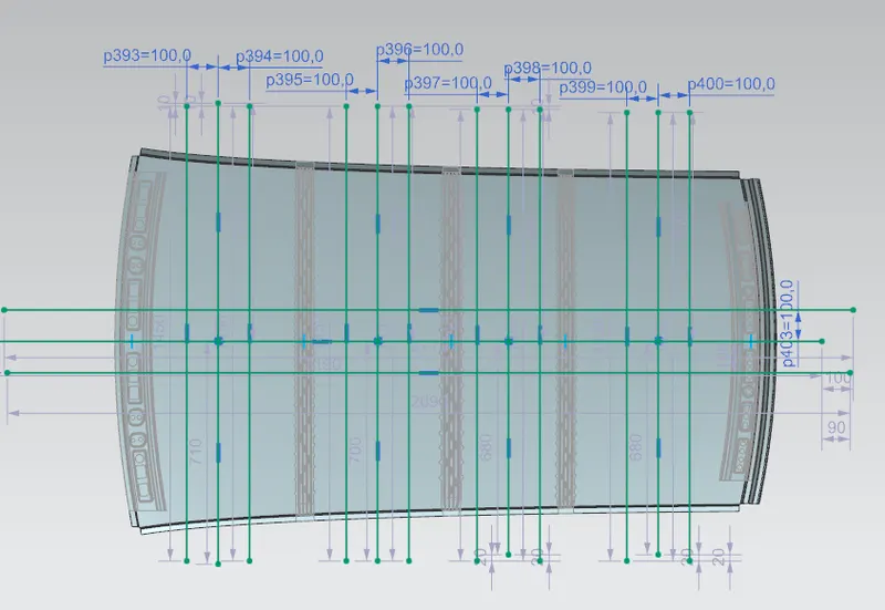
For Geometrical moment of inertia we need to calculate the minimum moment of inertia using the section inertia analysis at each bow roofs, and shown in the fig.
(1) Bow roof 1
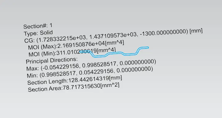
(2) Bow roof 2
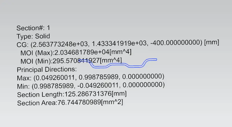
(3) Centre reinforcement rail
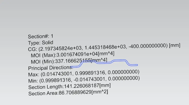
Calculations are done and tabulated in the below table :

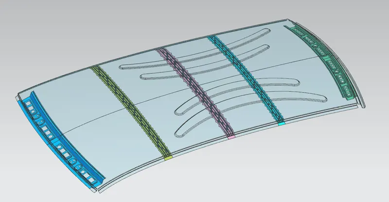
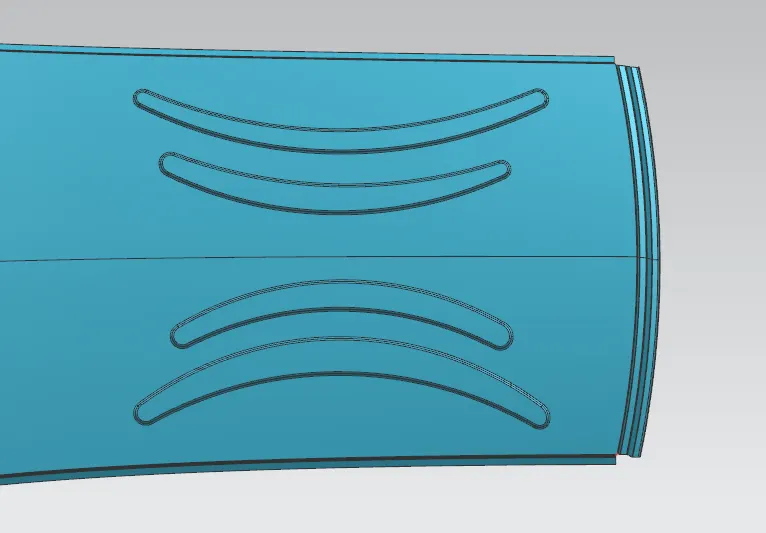
From the calculations we found bow roof 2 happens to be NG, So we have to ask the styling team to modify the surface with curvature in y. If team is rejected to do modification on curvature, we can provide emboss in the roof shown below. This embosses locally increase the strength of roof.
5. Draft Analysis:
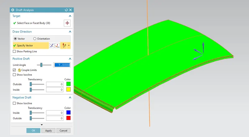
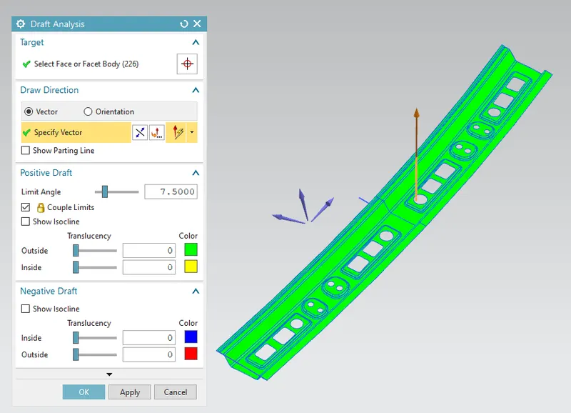
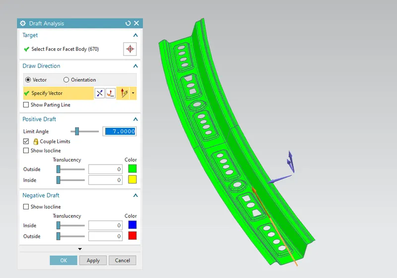
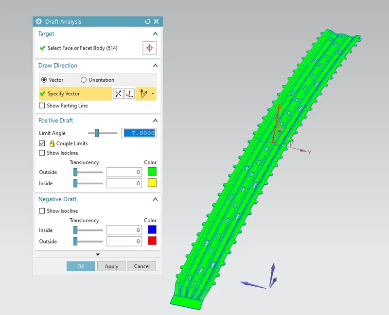
Draft analysis is a method of checking the draft angle on various faces of a part with a particular direction. it should be more than 7 deg.
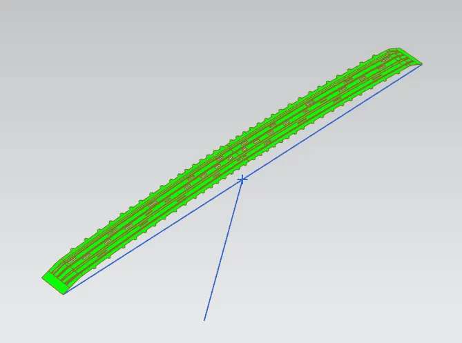
The following figure shows the draft analysis for Roof, Front Roof Rail, Rear Roof Rail, Bow Roofs and Reinforcement Center.
RESULTS:
The Design of Roof, Front roof rail, Rear Roof Rail, Bow Roofs, and reinforcement roof center by following the Master section with the design parameter for the given class A surface is done and the final model is shown in the fig. below.