Week 9-Challenge
AIM:
To create connectors on respective areas of a mid surface model inorder to connect or rigidize the model.
PROCEDURE:
- Import the .STEP file from the file source folder. Use the option Import from geometry
- In this model, 2D mesh need to performed with the given element size.
- Ensure that on meshing look for the hole areas to avoid trias from free edge.
- After the meshing is complete, remesh the surface to get a proper mesh flow.
- In this model certain connections need to be created on some areas of the model to achieve rigid connections.
- Connectors are geometric entities which are primarly used to represent the CAD geometric connection in terms of FEA.
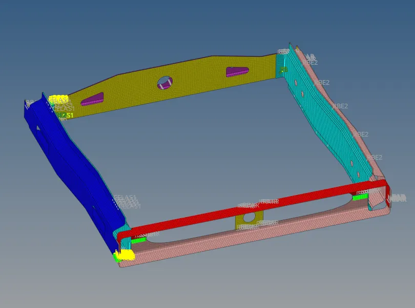
- The model is divided into sub surfaces, inorder to have rigid connection. Below image shows a clear idea of the model
- In Right_Rail_2 & Front_truss_1 perfrom Seam-Quad(angled+capped+L) connection.
Steps to perform Seam-Quad(angled+capped+L) connection are:
- Select 1D/2D-> Connectors->Seam option
- Now select the location, where the weld has to be created by clicking the Node list
- Tick the checkbox of retain nodes option to retain the position of the nodes , while creating and realizing a connector
- Specify the spacing value and select the comps option under connect what, inorder to create the weld between those two components
- Specify the tolerance value based on the distance between the two components
- Select the type as Seam-Quad(angled+capped+L)
- Click on the create button to create the seam weld.
- After completion of the seam weld , the components will connected shown as below
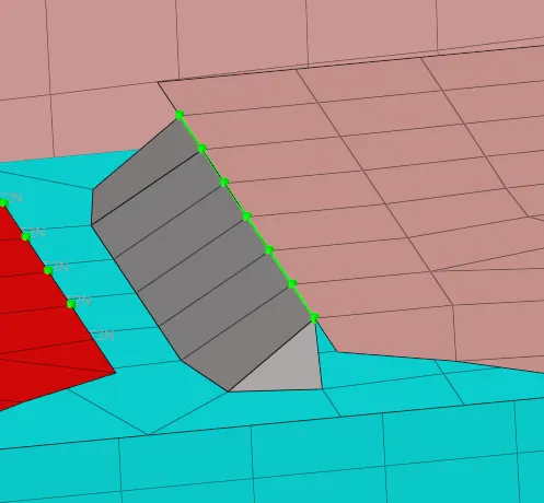
In Seam weld connections there are main 3 terms need to note about
Weld Angle: The angle between the normal projection of nodes and slant length of the weld elements
CAP angle: Angle between the normal of the first slant weld element (A) and its adjacent side elements (B)
Run off angle : Angle between the first slant weld element and its adjacent wel elements

In Left_Rail_2 & Front_truss_1 perform Quad connection
Steps to perform Quad connection are:
- Select 1D/2D-> Connectors->Seam option
- Now select the location, where the weld has to be created by clicking the Node list

- Specify the spacing value and select the comps option under connect what, inorder to create the weld between those two components
- Specify the tolerance value based on the distance between the two components
- Select the type as Quad connection
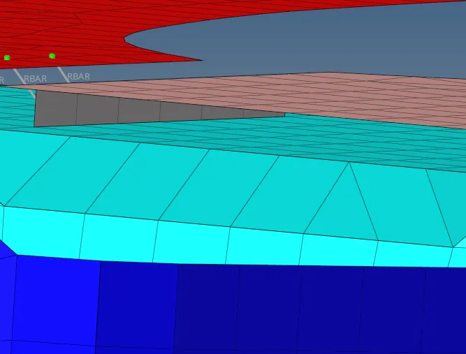
- After completion of the seam weld , the components will connected shown as :
In Front_truss_2, Front_truss_1 & Right_Rail_1 perform Spot weld with 3 Layers and 5 mm Diameter
Steps to perform Spot weld connection are:
- Select 1D/2D-> Connectors->Spot option
- Now select the location, where the weld has to be created by clicking the Node list
- Tick the checkbox of retain nodes option to retain the position of the nodes , while creating and realizing a connector

- Specify the spacing value and select the comps option under connect what, inorder to create the weld between those two components
- Specify the number of layers and diameter
- Specify the tolerance value based on the distance between the three components
- Select the type as weld
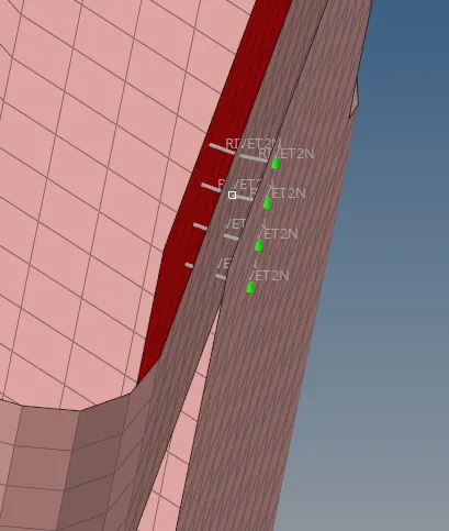
- After completion of the spot weld, the components will connected shown as :
In Front_truss_2, Front_truss_1 & Left_Rail_1 perform Hexa (Adhesive)
Steps to perform Hexa (Adhesive) connection are:
- Select 1D/2D-> Connectors->Seam option
- Now select the location, where the weld has to be created by clicking the Node list
- Tick the checkbox of retain nodes option to retain the position of the nodes , while creating and realizing a connector
- Specify the spacing value and select the comps option under connect what, inorder to create the weld between those two components
- Specify the tolerance value based on the distance between the three components
- Select the type as Hexa (Adhesive)
- Perfrom Hexa adhesive connection as follows:
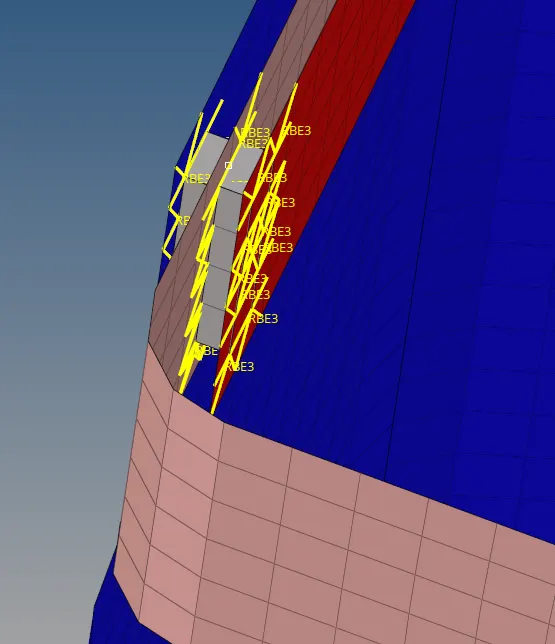
In Rear_truss_2 - Right_Rail_2 and Rear_truss_2 - Left_Rail_2 perform Bolt Connector
Steps to perform Bolt Connector connection are:
- In order to create a Bolt connection, first change the optistruct to Radios mode. Then only Bolt connection will get deployed on the surface
- Here 2 surface is not having holes, so hole need to be created
- Click 1D/2D-> Connectors->Bolt option
- Under location select the node which we create to establish the Bolt connnection
- Slect the comps in order to create Bolt connection
- select the number of layers to be welded under the "num layers" option
- Specify the tolerance value based on the distance between the two components
- Select the type as Bolt general
- Specify if hole is not available, change the option to "create a hole, if none".
- Perfrom Bolt Connector connection as follows:
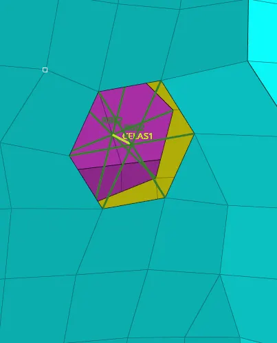
In Right_Rail_1 & Right_Rail_2 perform Spot-weld with Rigid Elements
Steps to perform Spot-weld with Rigid Elements are:
- Select 1D/2D-> Connectors->Spot option
- Now select the location, where the weld has to be created by clicking the Node list
- Tick the checkbox of retain nodes option to retain the position of the nodes , while creating and realizing a connector
- Specify the spacing value and select the comps option under connect what, inorder to create the weld between those two components
- Specify the tolerance value based on the distance between the three components
- Select the type as "Rigid"
- Perfrom Rigid connection as follows:
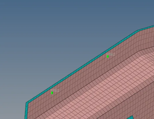
In Left_Rail_1 & Left_Rail_2 perform Spot-weld with Spring Elements:
Steps to perform Spot-weld with Spring Elements are:
- Select 1D/2D-> Connectors->Spot option
- Now select the location, where the weld has to be created by clicking the Node list
- Tick the checkbox of retain nodes option to retain the position of the nodes , while creating and realizing a connector
- Specify the spacing value and select the comps option under connect what, inorder to create the weld between those two components
- Specify the tolerance value based on the distance between the three components
- Select the type as "Spring"
- Perfrom Spring connection as follows :
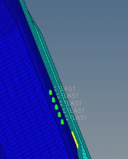
In other areas Spot weld and Seam weld connections are generated:
CONCLUSION:
The given model of frame assembly which is made of different parts have been connected together using various 1D connections and made it rigidised.