Week 11 - Final project
AIM:
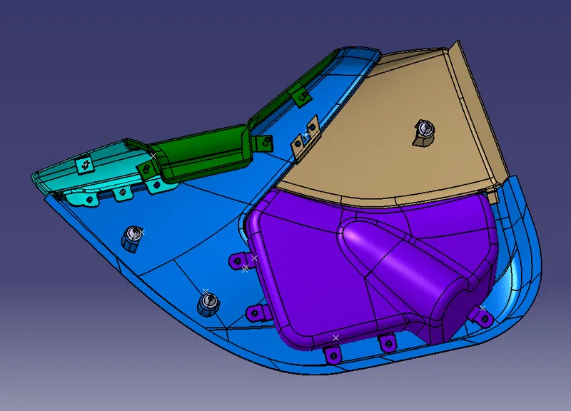
To create a CAD model of a Side Door trim panel considering the class A surface, nominal thickness and Attachment strategy.
OBJECTIVE:
Creation of side door panel of a car with the given class A surface and devolop the thickness along with the attachment strategy.
Creation of flanges and thickening can be devoped using the mastersections given.
Create the mounting features on the surface with the proper industry design guidlines with the help of mastersections given.
Draft analysis and Tooling axis has to be checked and created respectivily for each surfaces in the door trim panel.
INTRODUCTION:
The ten Stages of the Product life cycle of automotive Industry are given below:
- Concept sketch
- Styling class A
- Feasibility check
- Concept validation
- New Product Design
- Product Development
- Proto Build
- Design Validation
- Pilot Production
- Mass production
Out of which, the fifth stage is the New product design where a class A surface is devoloped and validated. With the given class A surface, we will design the class B as well as class C surafce and devolop a solid body out of it using various design softwares like Catia v5, solidworks or solidedge and with proper draft given for the injection molding process as per the industry guidlines.
The procedure followed in creation of the plastic New Product Design are
- Tooling axis
- B Surface Creation
- C Suraface Creation
- Closed Body Creation
- Draft Analysis
Interior door trim panel of a car consists of four components:
1) Lower Substrate
2) Upper Substrate
3) Map Pocket
4) Door Arm Rest
PRODECURE:
1. Import the file from the file location by File-> Open-> Browse-> MASTER SECTION DEVOLOPMENT.igs file.
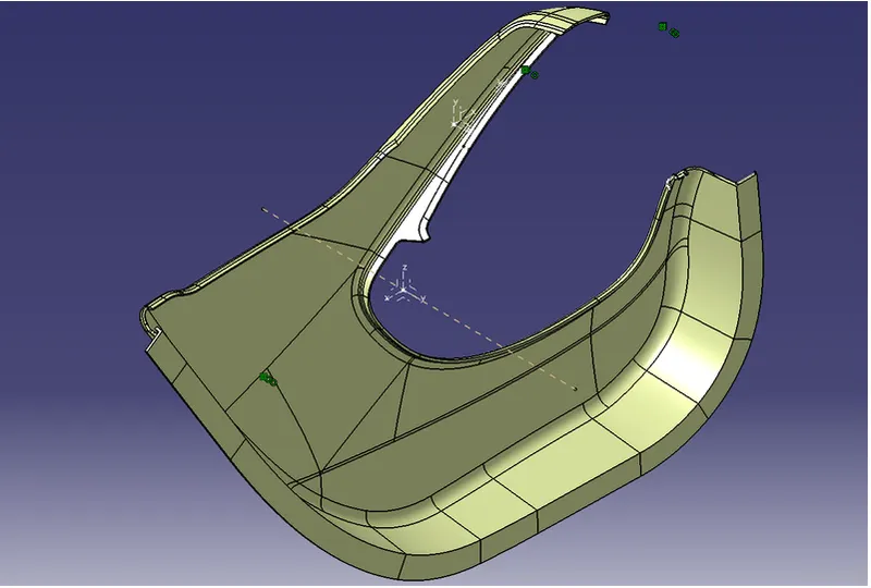
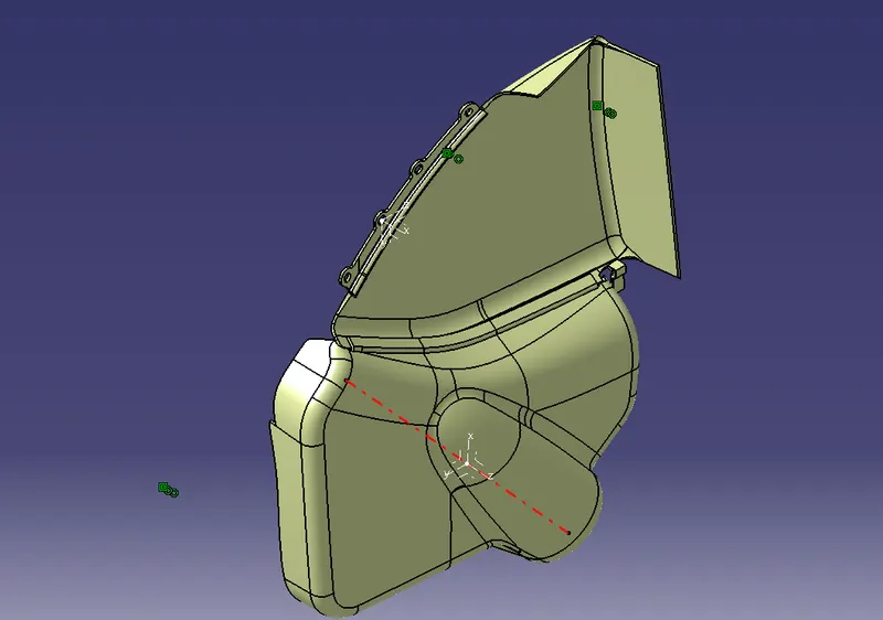
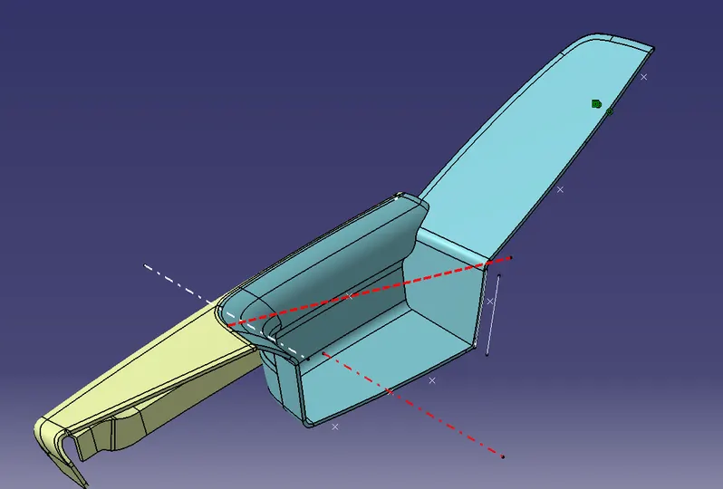
2. Next check the given class A surface for imperfections and the given Class A consist of mainly 3 parts: Lower substrate, Map pocket and Door arm rest.
3. Assemble all the parts accordingly into three main files along with their master sections as given above.
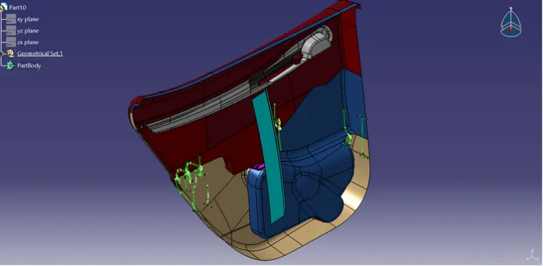
4.1. LOWER SUBSTRATE: Given lower substrate class A along with master surface is shown in the below fig:
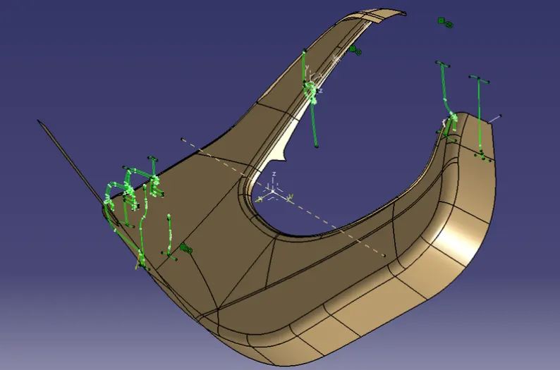
The master sections are given in the class A surface inorder to understand the flanges and attachments clearly along with their dimensions properly
The next process or step is to create the tooling axis for the part which can be either made using the Biscecting method or using the Draft analysis approximation method. When checking the draft analysis all top surface has to turned green.
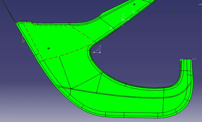
4.2. MAP POCKET: The given Class A surface of Map Pocket along with their master surface is given below:
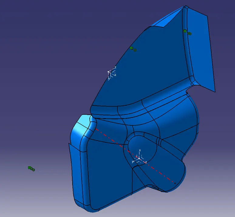
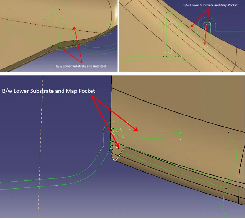
The master sections given in the map pocket to define the flanges is given below:
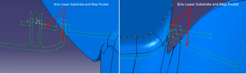
Here the Map pocket is divided into two parts where two of which is connected with the lower substrate itself. Find the tooling axis for both the surfaces by performing draft analysis using draft analysis tool (Insert > analysis >draft analysis).
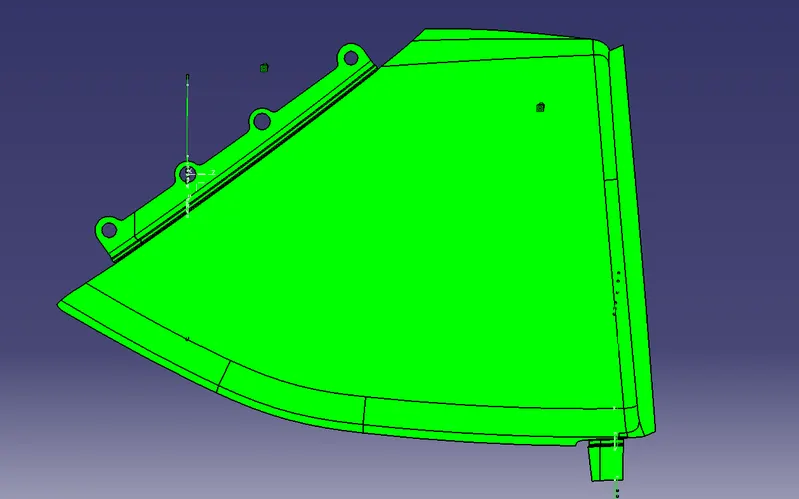
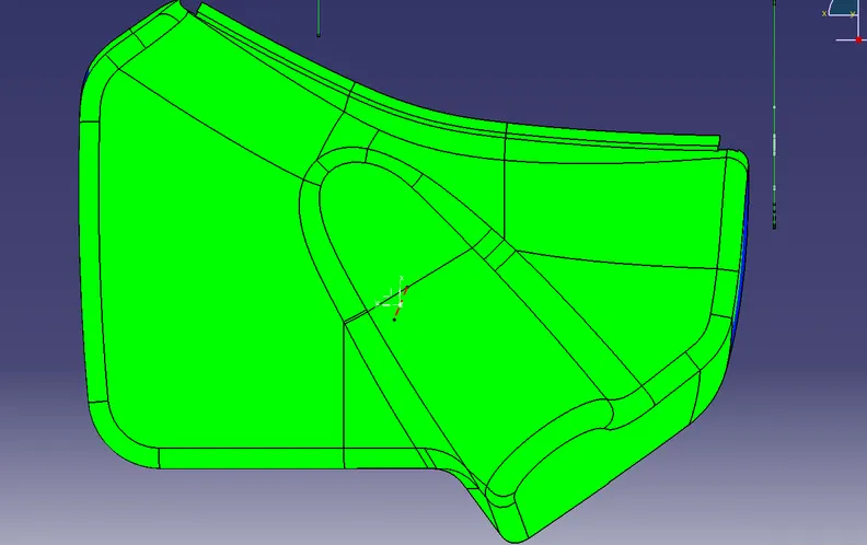
4.3. DOOR ARM REST : The class A of Arm rest along with the master surface is given below:
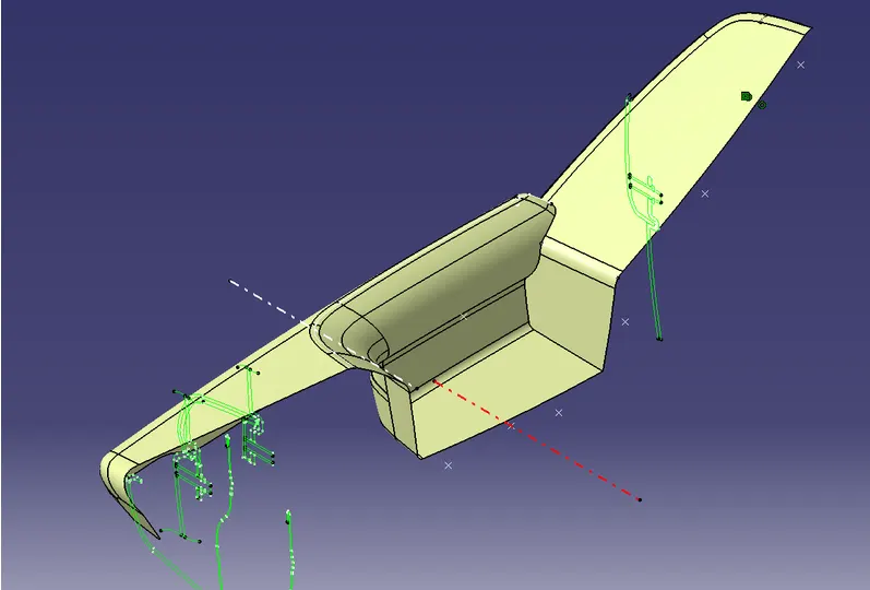
The master sections given in the Arm rest to define the flanges is given below:
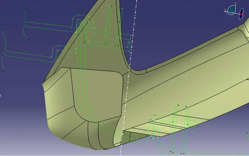
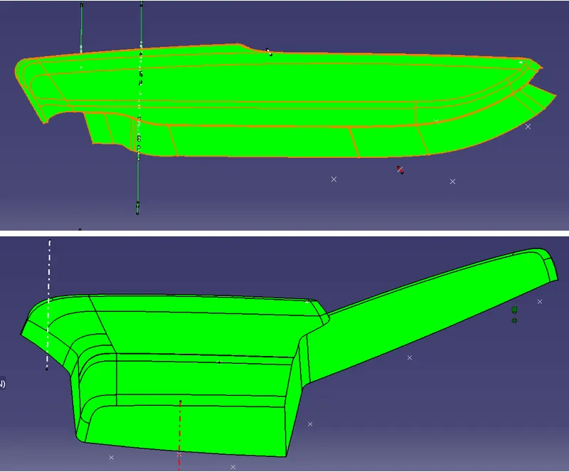
The Map pocket is also divided into two parts as whole of the arm rest wont go through one main tooling, so that the entire part has to be divided into two in a way it will pass through the two tooling devoloped. Find the tooling axis for surface by performing draft analysis using draft analysis tool (Insert > analysis >draft analysis) for two parts.
5. CLASS B CREATION:
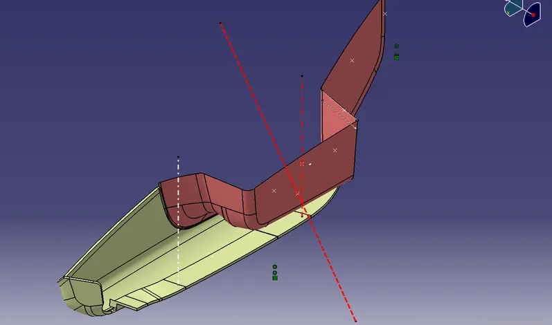
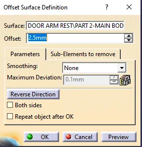
The Class B surfaces of all the parts is devoloped from the Class A surfaces by directly offseting the class A with a value of 2.5mm.
For example, in the case of arm rest the offset for one part is shown below:
The tool used for ofseting the surface is the Offset tool available in the Surface tools panel.
6. CLASS C SURFACE CREATION:
The class C surface means providing the thickness to the surfaces(between class A and class B surface) inorder to make it a closed body.
It is created based on the tooling axis, when the C surface is parallel to the tooling axis
The tools used for creating C Surface are:
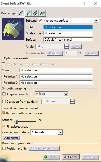
Creating Sweep surfaces with reference surface: The sweep tool is used to devolop the surfaces by sweeping a profile along a guide curve along the required area. To create a swept surface, you first need to define a profile and a guide curve as two separate sketches
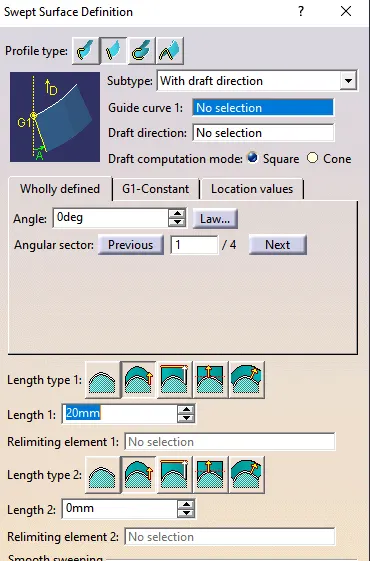
Creating Swept surfaces with draft direction: similar to the Creating Swept surfaces but instead of selecting the reference surface, we have to select direction for draft.
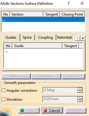
Creating Lofted Multi Section Surface: This tool allows you to create lofted multisection surfaces anywhere just to close the surface. The surface is created between the sections along the computed or user-defined spine. To create a multi section surface, you first need to create sections and guide curves. Next, choose the Multi Sections surface button from the Surface toolbar; the Multi-sections Surface Definition dialog box is displayed.Note that while selecting the section, the arrows must face towards single direction.
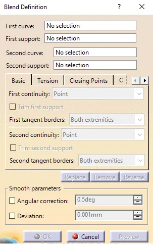
Blend tool option can also be rarely use if any of the above tools didnot work at a purticular area.
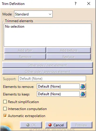
7. Next important step is the Final trimming of the Class A, Class B and Class c surfaces where trimming class A , with class C and Class A + C with Class B. using Trimming Surfaces Insert > Operations > Trim option tool.
The Trim tool allows you to trim two intersecting surfaces or curves with respect to each other. When you invoke this tool, the Trim Definition dialog box will be displayed, Choose a surface as the first element and the other surface as the second element where you have to select only the section of the part you want. One side of each surface will be displayed as transparent, which will be removed. You can choose the Other side button to reverse the sides of surfaces to be trimmed.
After trimming is done, check the boundary of the part and if it shows as a closed boundary then the part can be converted into a closed body. The use of Join tool can be used only upto a maximum merging distance of 0.003
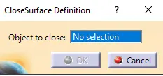
Inorder to make a closed body, goto the part design workbench,define in a partbody and select the close surface definition tool where click on the part and click OK.
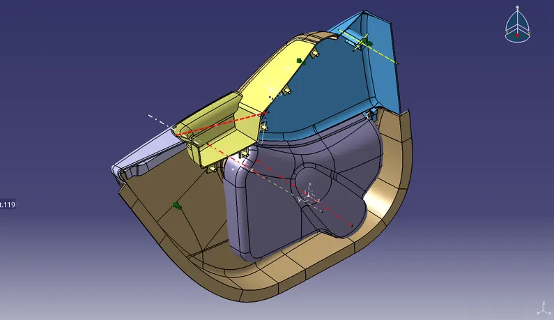
The closed body of all three parts are shown below:
The below fig. shows all closed surfaces of Lower substrate, Arm Rest and Map pocket
8. After all the surfaces has been created and made it as closed body, next is the creation of B side features and attachments on the inner part or class B surface.
9. The Attachments include Heat stakes, Ribs on corner edges, doghouse with pushpins etc..
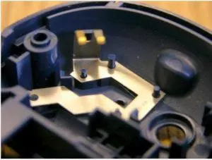
10. HEAT STAKES: It is defined as the pulsed-heat process to join two or more parts out of which one at least is made of plastic. The process is to deform the plastic material using heat and force at a set process time. The bond is made by partially de-forming the plastic part in order to fix the other.
The heat stakes devoloped in the cad model for the lower substrate is shown below:
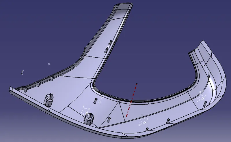
Similarly for the heat stakes made, holes have been created in the other parts like door arm as well as map pocket
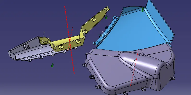
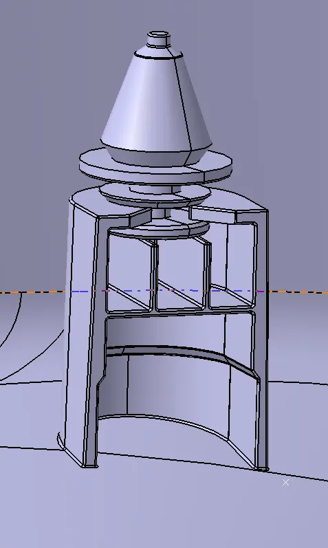
11. DOG HOUSE WITH PUSH PINS:
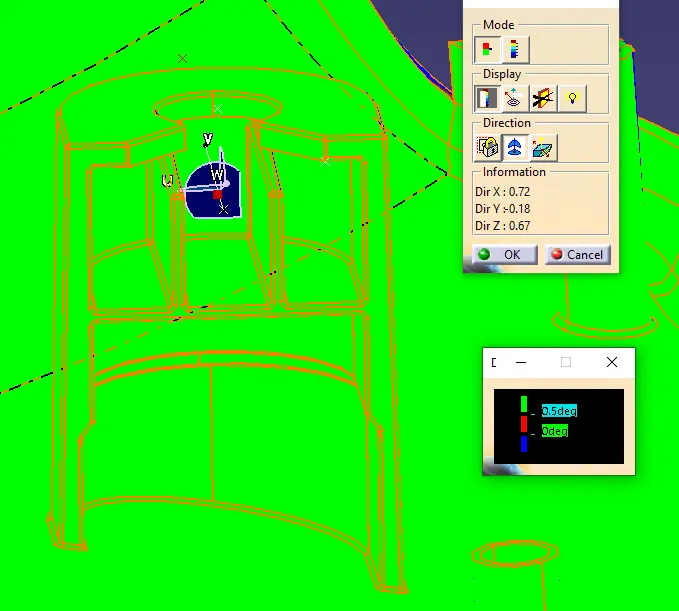
Dog houses are used as supporting feature inorder to increase the height to attach the features to the opposing surface. Sometimes other engineering features like snaps or locators etc. are mounded on them to increase their strength. Dog houses are subjected to draft analysis(outer-1.5 and inner-0.5) to prevent breakage of the component during ejection from mould cavity.
The 2-D drawing of dog house along with the solid part of push pin is given below for reference
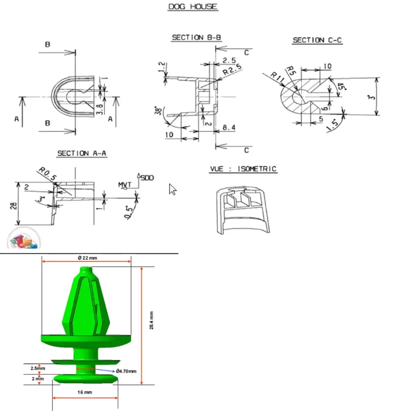
The devoloped model of dog house and pushpins in the 3D part is shown below:
12. Draft analysis & Tooling analysis:
In the injection molding process, plastic products are difficult to demold due to friction force between the cavity and products, thus, finished products might be deformed or damaged. Therefore, designers should add a draft angle to the geometric surface of products, which is parallel to the unloading direction, in order to help the products eject smoothly from the cavity. This study uses CAD software as the main architecture to develop the function of automatic draft angle recognition and construction. The study is divided into three stages. First, the geometric features of products are identified in the CAD model by induced algorithm, then the quilts to be added in the draft design are determined and classified. Finally, draft angles are created in different ways according to different surfaces
The draft analysis button within CATIA V5 will help you quickly gather the draft angle on multiple surfaces without the need for tedious manual measurements.
(A) MAP POCKET - PART 1
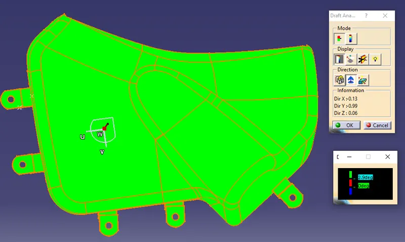
MAP POCKET - PART 2
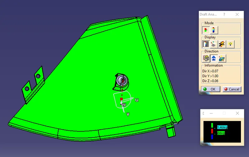
(B) LOWER SUBSTRATE

(C) DOG HOUSE INNER PORTION DRAFT=0.5DEGREE
(D) ARM REST - PART 1
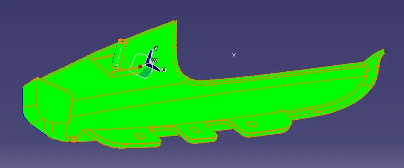
ARM REST - PART 2 (MAIN TOOLING)
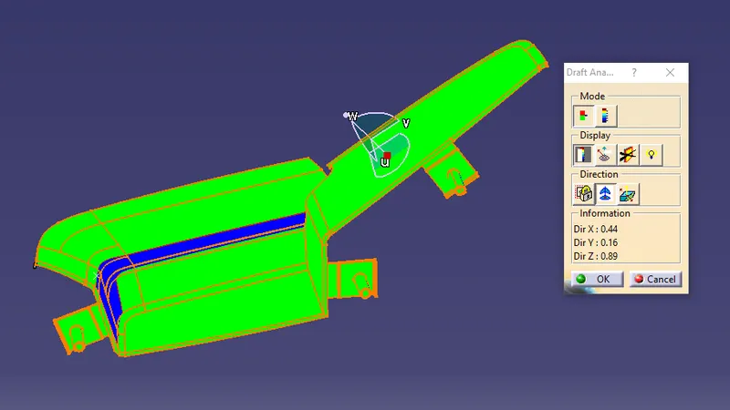
ARM REST - PART 2 (SIDE CORE AXIS)
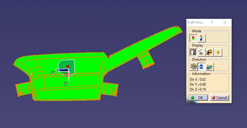
13. As some of the master sections are missing in the model for the map pocket connection flanges and the heat stakes, so we created extra flanges with heat stakes as shown in the below figure.
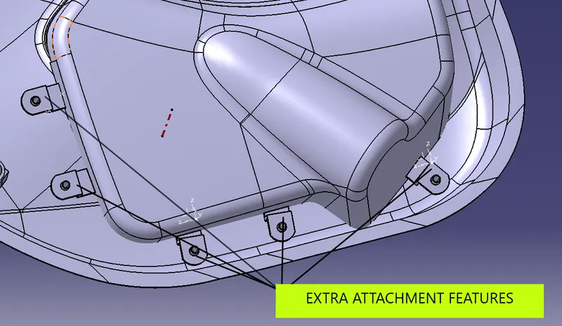
The final designed product of side door panel consisting of all the attachment features is shown below