Section Modulus calculation and optimization
AIM:
To create the section for hood and calculate Section Modulus and optimize the Section Modulus for the same.
INTRODUCTION:
Section modulus is a geometric property for a given cross-section used in the design of beams or any component with flexural properties. Other geometric properties used in the design include an area for tension and shear, the radius of gyration for compression, and moment of inertia and polar moment of inertia for stiffness.
It involves the mathematical properties of structural shapes, where they are of great use in structural analysis and design. Note that these properties have nothing to do with the strength of the material, but are only based on the shape of the section. Those properties are given below:
- centre of area (or centroid)
- second moment of area or moment of inertia (I)
- section modulus (S)
- radius of gyration (r)
Centre of area (or centroid): The centroid of a section is important in structural design and is like the centre of gravity of the shape. Many other simple shapes are symmetrical about the x-x and y-y axes and the centroid can easily be seen.
Second moment of area or moment of inertia (I): The second moment of area is a geometrical property of an area which reflects how its points are distributed with regard to an arbitrary axis. The second moment of area is typically denoted with either an I.The second moment of area is also known as the moment of inertia of a shape. It is directly related to the area of material in the cross-section and the displacement of that area from the centroid. Once the centroid is located, the more important structural properties of the shape can be calculated. The axis that determines the centroid is also known as the neutral axis (N/A).
Section modulus (S): The section modulus of the cross-sectional shape is of significant importance in designing beams. It is a direct measure of the strength of the beam. A beam that has a larger section modulus than another will be stronger and capable of supporting greater loads. Section modulus is denoted by S. To calculate S, the distance (y) to the extreme fibres from the centroid (or neutral axis) must be found as that is where the maximum stress could cause failure.
Calculating the section modulus by S = I/y
where I = moment of inertia, y = distance from centroid to top.
For symmetrical sections the value of S is the same above or below the centroid. For asymmetrical sections, two values are found: S max and S min.
Radius of gyration (r): This is another property of a section and is also a function of the second moment of area. Put in general terms, the radius of gyration can be considered to be an indication of the stiffness of a section based on the shape of the cross-section when used as a compression member.
The radius of gyration is used to compare how various structural shapes will behave under compression along an axis. It is used to predict buckling in a compression member or beam.
The formula for the radius of gyration r is:
r=√IAr=IA in mm
where I = second moment of area
A = area of material in the cross section.
PROCEDURE:
1. Create a Datum plane in the middle of the body so that the section can be taken at the half portion.
2. Create an Intersection curve for outer panel and inner panel in the plane created using the intersection curve tool in the Curve panel.
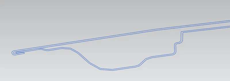
3. By hiding all the parts, we will be able to see the section curve devoloped which is shown above:
4. Boundary for Cross sectional area: In order to calculate Moment of Inertia, we have to create 2D cross section plane, for creating the sketch, following are the procedures:
- select outer most intersection line of outer panel and inner most intersection line of inner panel.
- Fill in gaps by using Spline and make sure that there is no any gap or discontinuity.
- The gap between the inner panel and outer panel for this case is 5mm.
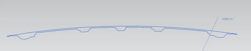
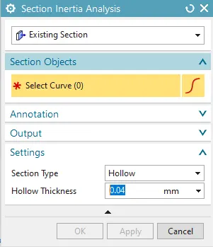
5. Now using section inertia analysis tool, keeping in the existing section, selec the curve devoloped and make sure the section type is given as hollow and click OK.
6. A PMI (Product Manufacturing Information) tab will be shown in the graphics panel along with a folder formed in the part navigator. Take a note on the minimum MOI formed in this case.
7. Similarly increase and decrease the gap between the inner and outer panel by 1mm (where change has to be done on the outer panel) and note the min MOI in these two cases.
RESULTS:
- For the first initial case, the min MOI formed is shown below in the PMI table:
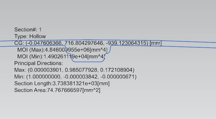
From the fig. we have MOI(Min) and MOI(Max) of I which is M1 and M2.
M1 = 1.490 X 10^4 mm^4
M2 = 4.846 X 10^6 mm^4
y = distance between the neutral axis and the extreme end of the object = 438.294mm
So
S1(min) = I/y
= 1.490 X 10^4 mm^4 / 438.294mm
S1 = 33.9954 mm^3
- For the second case, when the outer panle is offseted 1mm above(gap increased), the min MOI formed is:
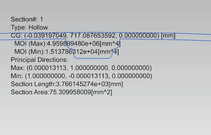
From the fig. we have MOI(Min) and MOI(Max) of I which is M1 and M2.
M1 = 1.513 X 10^4 mm^4
M2 = 4.959 X 10^6 mm^4
y = distance between the neutral axis and the extreme end of the object = 438.294mm
So
S1(min) = I/y
= 1.513 X 10^4 mm^4 / 438.294mm
S1 = 34.520 mm^3
- For the third case, when the outer panel is offseted 1mm below(gap decreased), the min MOI formed is:
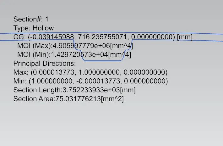
From the fig. we have MOI(Min) and MOI(Max) of I which is M1 and M2.
M1 = 1.429 X 10^4 mm^4
M2 = 4.905 X 10^6 mm^4
y = distance between the neutral axis and the extreme end of the object = 438.294mm
So
S1(min) = I/y
= 1.429 X 10^4 mm^4 / 438.294mm
S1 = 32.60 mm^3
CONCLUSION:
As we knew larger section modulus than another will be stronger and capable of supporting greater loads and have high structural stability when the gap between the inner and outer panel is increased. So from the above we can see that 2nd case has more section modulus so by increasing area we can get more stronger and capable of supporting greater loads
So by changing section area, we can change the strength of hood, so depending on the feedback from the CAE team we can change strength.
Hood should design in such a way that it should absorb all maximum loads when a crash happens. So while designing we have design in such a way that it should not be more stiffer and not more weeker.