Assignment 1
AIM:
To create the midsurface as well as meshing on the given three components of Practice model, Clip repair and Mounting bracket with proper feature capturing and given Quality criteria with target length as 5mm, minimum length as 3.5mm and maximum length as 7mm.
METHODOLOGY:
- Import the hypermesh model from the repective file location by using File->Open->Model option in the menu bar.
- Analyse the given models carefully and check for deformations as well as free edges in the surfaces which must be rectified before extracting the mid surface out of the geometry.
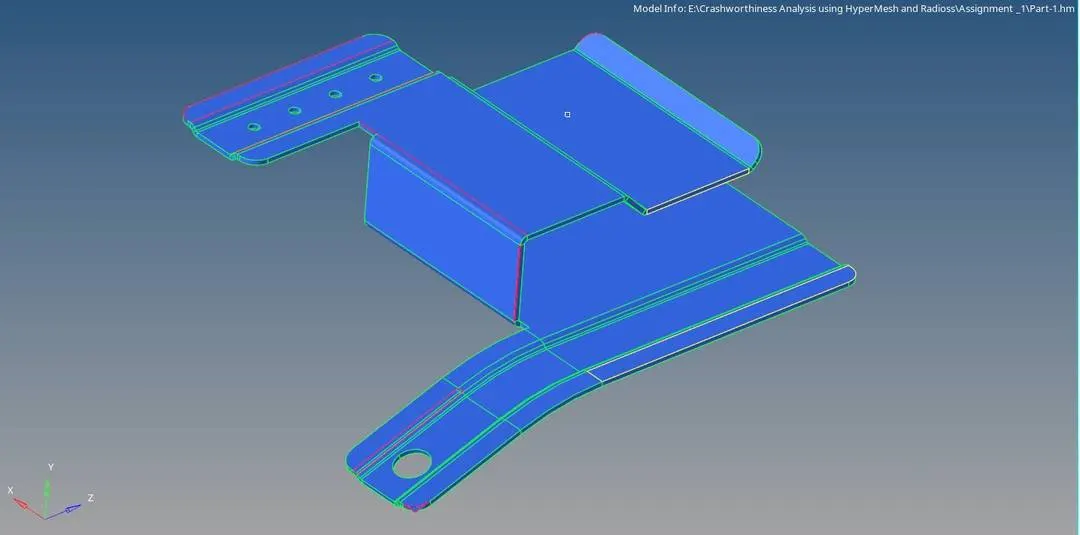
- In the given 3 models there are some topology problems on the surface. In the given below model the surfaces with red lines are the free edges, which has to be removed.
- After the topology cleanup, next is the extraction of mid-surface. Since it is a sheet metal component, the thickness of the entire surface will be same throughout.The mid surface of the given model is taken out using the Auto-mid option available in the Geometry panel.

- The automid with the skin offset has succesfully given the midsurface of all the three given component.The extracted midsurface of all the three given components are given below:
- After which, defeature the models as per the minimum length value which here is 3.5, so that the elements wont fail, while the time of meshing.
- Also, the holes which are less than 5mm can be ignored and fill the holes using the Filler Surf which is available in Quick edit toolbar, which can be directly acessed using F9 button.

- Next important step is the meshing of the components with the given quality criterias. Inorder to input the values of the QA, go to Preference tab->Criteria file settings and the below tab will be opened and select the required checks as given in the question.
- This can be acheived using the Automesh tool available in the 2D panel.
- In the Automesh tool, select the entity as surfaces, and the element size as 5mm, mesh type as mixed, swich on the keep connectivity option and in the flow option, Align and size must be ticked on, so that a proper mesh flow will be formed.
- Once the meshing is done on a surface, change the entity from surface to elements, so that a portion of elements can be remeshed and a better mesh can be generated on the surface.
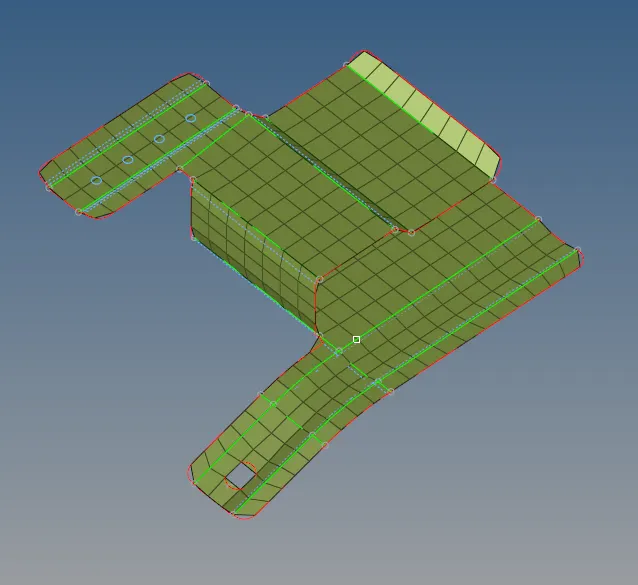
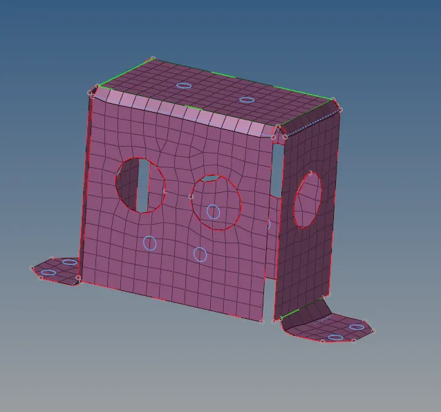
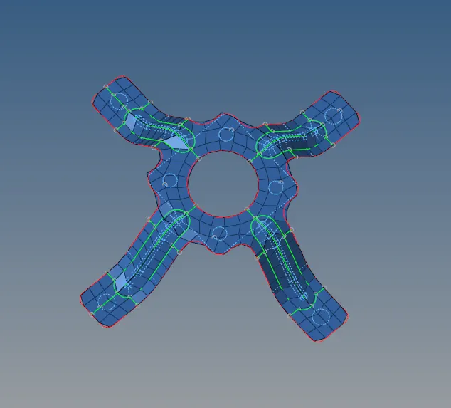
- The meshed surface of all three components are given below:
- After all the model has been completely meshed, check for free edges ,normals and feature capturing which has been done correctly.
- Free edges is the most important part in this, as it determines the connectivity between the nodes. This can be found using the Edge option available in the Tool panel.Change the entity mode to elements and window select the elements and click find edges.
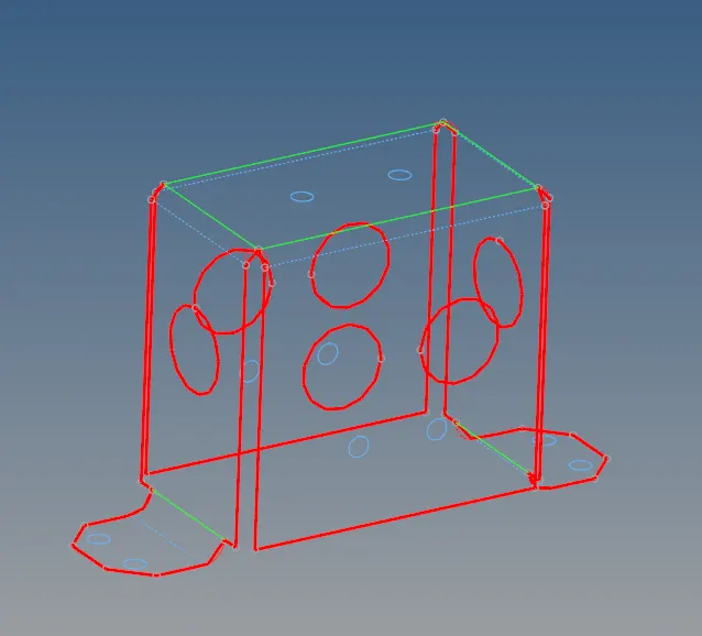
- The normals can also be checked using the normals tool available in the Tool panel.In that option just click on display and change the colour display to vector display and if needed change the size to any higher value. If the vector points outward for the entire surface then the normals for the current model is good.
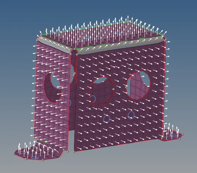
- The next step after completing all these conditions is the assigning thickness to each three components by creating properties in the entity tab and in the pop-up box assign the respective thickness for each componnets.
- Practice model-0.91mm, Clip repair-2mm, Mounting bracket-1.8mm
- The thickness has to be assigned to each components by right clicking on each components and select Assign option and give the respective property to it.
- The thickness assigned can be viewed by changing from 2D Traditional Element Representation to 2D detailed element representation.
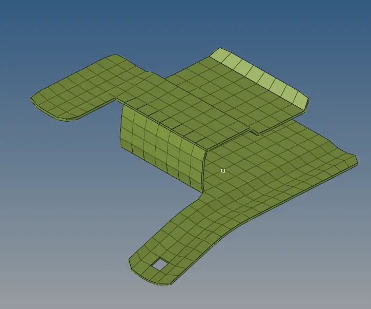
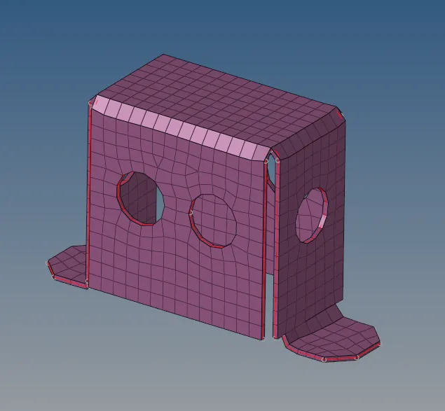
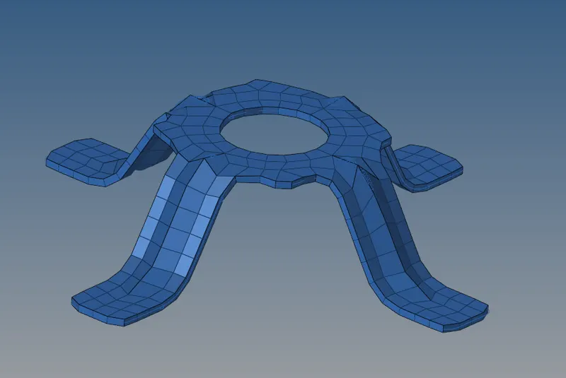
RESULT:
The given three models has been succesfully done with shell mesh by extracting the mid surafce out of it with the given Quality criteras given.