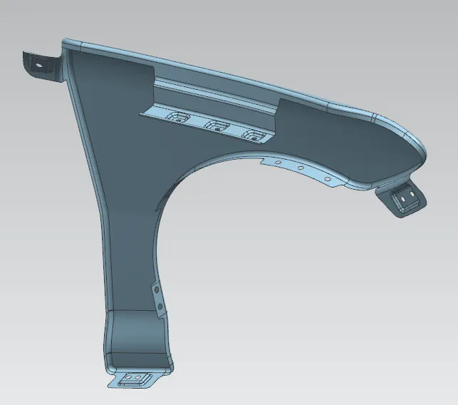
Fender Design Challenge
AIM:
To devolop and design a fender with the given mastersection for the drip area and create flanges in all other respective mounting areas following the design parameters.
INTRODUCTION:
Fender is the American English term for the part of an automobile, motorcycle or other vehicle body that frames a wheel well (the fender underside). Its primary purpose is to prevent sand, mud, rocks, liquids, and other road spray from being thrown into the air by the rotating tire. Fenders are typically rigid and can be damaged by contact with the road surface. Material used in fender is Steel or aluminum.
Fender is a front outer side member of a car, which covers the wheel side. It has so many small features with ups and downs. The binder surface is not a planer one in this case. This is because it reduces the draw depth and it has two rows of draw beads.
Various materials are used to make cars. The main materials used for making cars, parts and components, along with future trends, are steel, aluminum, magnesium, copper, plastics and carbon fibers. The prime reason for using steel in the body structure is its inherent capability to absorb impact energy in a crash situation. The use of aluminum can potentially reduce the weight of the vehicle body. Recent developments have shown that up to 50% weight saving for the body in white can be achieved by the substitution of steel by aluminum.
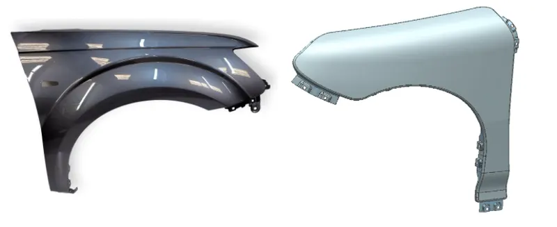
It seems to be difficult to form due to their small radius fillets. In this analysis, there is a need to find out the forming feasibility of this component and if not possible in single stage then we need to modify the die design with least modification and need to optimize the draw bead profile and draw radius in such a way that we can get the good component in a single stage itself. For thin and very big forming dies, we need to do gravity analysis. If our die face is profiled one, then we may need to do binder wrap analysis. The binder wrap analysis results are taken to the forming analysis. After the forming analysis, if trimming is there means just before trimming analysis we have to do mesh coarsening. Then the coarsened mesh and its results are taken for trimming analysis. The results of the trimming analysis are taken to the spring back analysis. From the results of the spring back analysis, further we can cross check the spring back of the real component. The analysis results obtained are used in the sheet metal industry for metal forming processes.
Below figure shows the fender location on the car where it is mounted on the front and rear side.
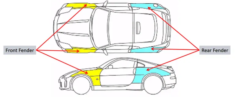
There are basically 2 types of Front Fender
- Full Bumper Type
- Half Bumper Type
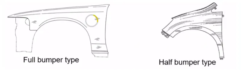
We have changed the design from full bumper type to half bumper type to reduce scrap rate per blank. In full bumper we can only produce one Fender per blank, whereas as a half bumper type we can produce 2 fenders per blank.
Fender Design
The Fender has 5 important regions :
1) Body :- It is the Front part of the Fender which houses other components. It is the largest part in a Fender.
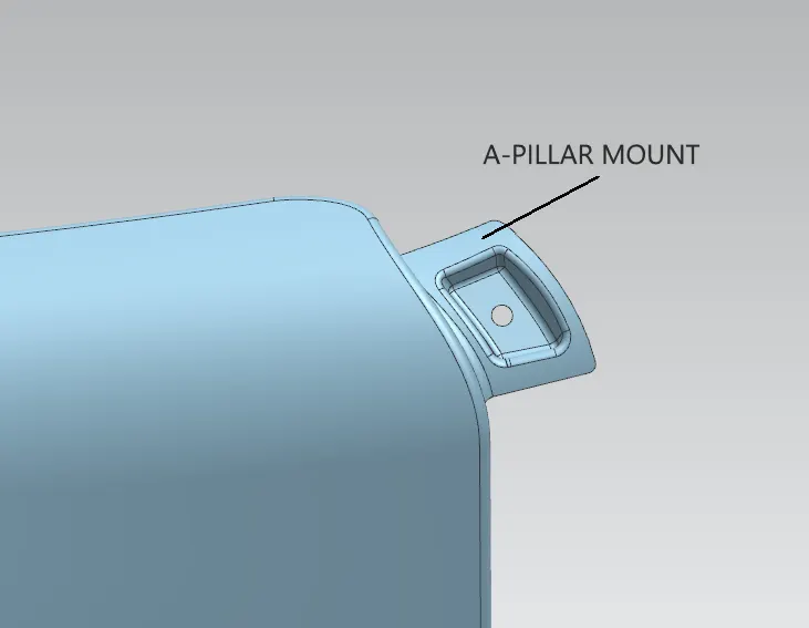
2) A-Pillar mounting area :- Pillars are vertical supports on a vehicle. They are located around all the glass on an automobile. They are important for holding glass in place and adding structural integrity to a vehicle and also connected to the body side of the vehicle. A-pillar is located on either side of the windshield at the front of the car.
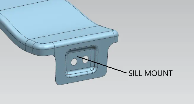
3) Sill mounting Area :- This Area links the fender with the sill (Underside of the door) of the car. Bolts are used to fix the fender.
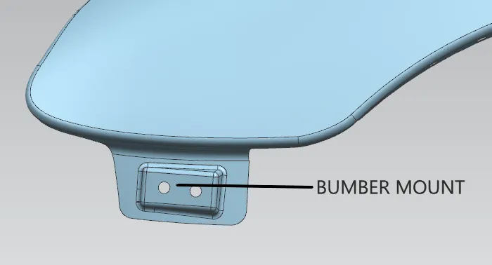
4) Bumper mounting region :- This connects the fender with the front bumper of the car.
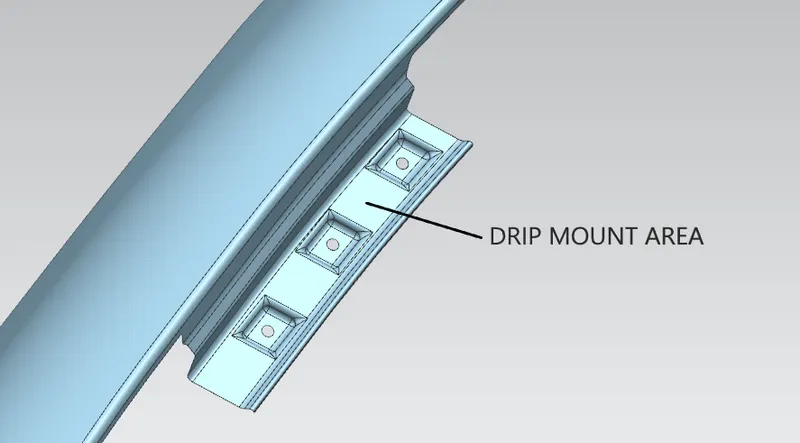
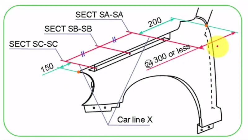
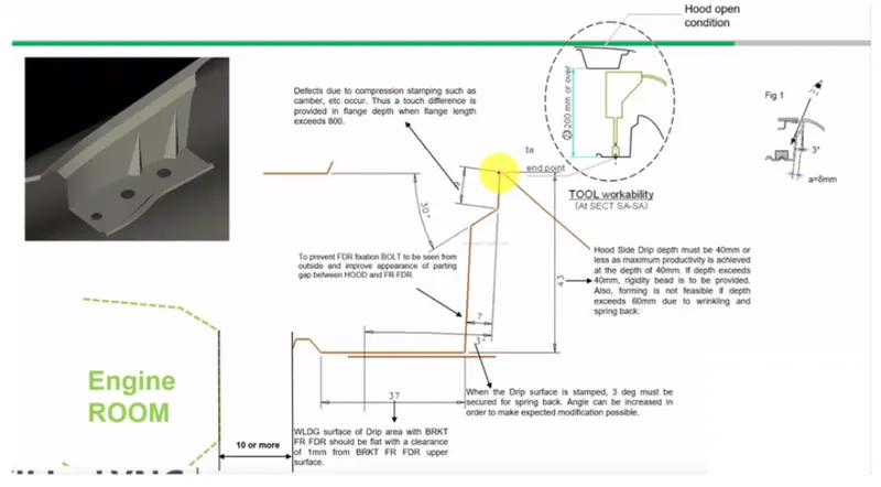
5) Drip Area :- This is the most important region in the fender design. As there are few standards set to design the drip area as it connects the fender with the engine compartment.
Manufacture of front Fender:
Generally the manufacturing of sheet metel are involved following steps
- Process planning: The purpose of process planning of automotive panels is to identify the number of operations, the tasks in each operation, and the content of each task. This researching proposes an automatic reasoning procedure based on expert experience and the laws of physics.
- Blank size calculation.
- Trimming task: The trimming task is separated into two parts.
- Restriking task: The restriking task is necessary when surfaces deform because of springback after drawing and trimming, or the accuracy requirement is high because a surface overlaps another surface of another panel during assembly. To over come spring back of sheet metal Restriking is required.
- Piercing task: Each hole feature requires a piercing task. Hole features can be classified as basic holes, lock holes, and enlarge holes based on their different functions during assembly. A basic hole is for locating the panel, and a lock hole is for locking panels.
- Burring task: Removing the sharp edges and harmfull burs from the component.
Design requirements for Fender:
- Check for Wheel arch area, as per regulation taken for design.
- Drip Area: The followingDesign requirements are used to desing drip area.
- Drip Area should 150 mm from the front side and 200 from the mirrior area.
- From the master section we have optimize values for draft, drawing and assembly point of view. such as Distance from engine comportment is 10mm, Height of fendrer etc.
DESIGN PROCEDURE FOR FENDER:
1. Import the .prt file from the folder location.
2. Check the Class A surface of fender has no imperfections and are free from defects.
3. The flanges for mounting the already given with the class A surface. Offset the entire flange curve 5mm below to create the mounting regions.
4. Using the Curve on surface and trim sheet operation, create and cut the flanges wherever necessary.
5. As per the masersections given for drip area, create the mounting as shown below:
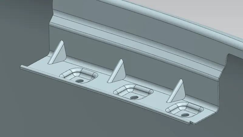
6. Three holes have been made within emboses to increase the structural capability with edge blends given in all sharp corners with minimum of 2.5mm radius.
7. Similarly create mounting flanges for A-pillar region, Sill mount region, bumber region as well.
8. Baffle mount flanges also has to be created with holes to fix the splash cover aroound the wheel arch area.
9. Note that the minmum gap b/w holes, hole and beside edge sholud be more then 5mm.
10. Inorder to increase the strength in corner regions of flanges, Beads or Darts can be given as stiffners.
11. The last and final step is to Thicken the model with an offset of 0.75mm