Assignment 4
OBJECTIVE:
1. Run the crash test of Ball and Plate Simulation with 7 different cases to be analysed and simulated.
2.From all these cases find:
- Total number of cycles, Energy error, mass error and simulation time.
- Notice the animation of all 5 and describe the animations in brief on the basis of whether the elements are being deleted or cracked.
- Plot energies and notice any difference.
- Based on all the results, which case would represent the on-field scenario.
- Prepare a ppt/docx and list down case by case result and your conclusion as to why the failure happened.
BALL AND PLATE SIMULATION MODEL:
SIMULATIONS:
CASE 1:
1. Open the hypermesh software in the Radioss user profile as we are doing an explicit solver analysis.
2. Import the .rad file using Import->solver deck->and browse for the file which is named as FAILURE_JOHNSON_0000 from the respective file location.Click Import so that the model will be available in the graphics panel.
3. In this case, the values has to be given as same defualt values and run the simulation.
4. Click on Radioss and a tab will be opened.Select the input file location where you have to save the model and give the name of the simulation as LAW2_EPSMAX_FAILURE, export option as ALL, run option as Analysis and run number as 1.In the option column, type -nt 4 to run the results much faster.
5. Then the software wil run the analysis ans shows the result.After computation is over, close the pop-up tab and change the panel to Hyperview panel.
6. In this panel, upload or browse for the .h3d file which is the animation file created for the respective model which shows the deformation happened when the ball strikes the plate.
CASE 2:
1. Open the hypermesh software in the Radioss user profile as we are doing an explicit solver analysis.
2. Import the same .rad file using Import->solver deck->and browse for the file which is named as FAILURE_JOHNSON_0000 from the respective file location.Click Import so that the model will be available in the graphics panel.
3. Open the enitity tab where we will get a failure card.In the failure card which named Failure_johnson_1, we have to change some of the input values as per the given question
4. The values to be changed are: Ifail_sh = 1, Dadv = 1 and Ixfem = 1 and save the file name to Law2_epsmax_crack during the time of analysis.
CASE 3:
1. Open the hypermesh software in the Radioss user profile as we are doing an explicit solver analysis.
2. Import the same .rad file using Import->solver deck->and browse for the file which is named as FAILURE_JOHNSON_0000 from the respective file location.Click Import so that the model will be available in the graphics panel.
3.The third case implies that the Failure card has to be deleted rom the entity tab and perform the simulation.
4. The file name for simulation must be given as LAW2_EPSMAX_NOFAIL.
CASE 4:
1. Open the hypermesh software in the Radioss user profile as we are doing an explicit solver analysis.
2. Import the same .rad file using Import->solver deck->and browse for the file which is named as FAILURE_JOHNSON_0000 from the respective file location.Click Import so that the model will be available in the graphics panel.
3. In the 4th case, goto the Material tab in the entity browser, change the value of EPS_p_max from 0.151 to 0 ,so that simulation will be runned without the application of eps_p_max.
4. Run the simulation with file name as Law_2.
CASE 5:
1. Open the hypermesh software in the Radioss user profile as we are doing an explicit solver analysis.
2. Import the same .rad file using Import->solver deck->and browse for the file which is named as FAILURE_JOHNSON_0000 from the respective file location.Click Import so that the model will be available in the graphics panel.
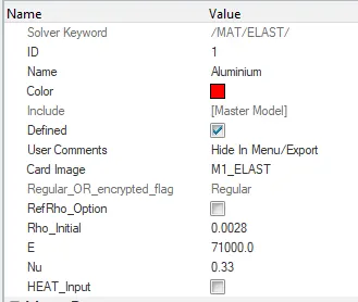
3. In the materials tab, change the card image from M2_PLAS_JOHNZERIL to M1_ELAST.
4. Before changing the material card,note the values of Rho, E and Nu ,which has to be inputed as same when changed to M1_Elasticirty.The value of rho, E and Nu are 0.0028, 71000 and 0.33 respectivily.
5. Run the simulation with file name as LAW1_ELASTIC
CASE 6:
1. Open the hypermesh software in the Radioss user profile as we are doing an explicit solver analysis.
2. Import the same .rad file using Import->solver deck->and browse for the file which is named as FAILURE_JOHNSON_0000 from the respective file location.Click Import so that the model will be available in the graphics panel.
3. In this case, a lot of changes has to be done as compared to the previous cases.
4.First a curve has to be created in the curves folder in the entity tab
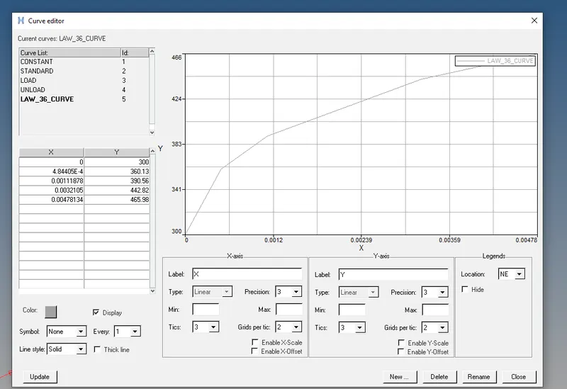
5. The values of X and Y has to be given as per the above values in the figure.
6. Change the Card image to Law36_PLAS_TAB.
7. Input the values of Rho, nu, E, Eps_p_max, Eps_t, Eps_m.
8.Run the simulation with file name as LAW_36.
CASE 7:
1. Open the hypermesh software in the Radioss user profile as we are doing an explicit solver analysis.
2. Import another .rad file using Import->solver deck->and browse for the file which is named as LAW27_0000 from the respective file location.Click Import so that the model will be available in the graphics panel.
3. This will be opened with Plast_Brittle material card as default.
4.Change the shell properties to the recommended shell properties.
Recommended properties:
| Parameters | Comment | |
|
Ishell =24 |
QEPH 4 nodes shells are best combination of cost and accuracy. | |
|
Ismstr=2 |
Full geometric nonlinearities (default)with possible small strain formulation activation in RADIOSS Engine. | |
|
Ish3n=2 |
Standard 3 noded shell (C0)with modification for large rotation(default) |
|
| N=5 | Number of integration points set to 5 for accuracy bending. | |
|
Ithick=1 |
Thickness change is taken into account for accuracy. |
|
|
Iplas=1 |
Iterative plasticity for good accuracy. |
5.Run the simulation with file name as Law_27.
TOTAL NUMBER OF CYCLES, ENERGY ERROR RATE,MASS ERROR, SIMULATION TIME:
| Cases | Total number of cycles | Energy error limit(%) | Mass Error limit(%) | Simulation Time |
| 1 | 49380 | 0.4% to 1.2% | 0.000 | 101.95 |
| 2 | 49217 | -1.1 % to 4.2% | 0.000 | 99.94 |
| 3 | 49408 | -0.3 % to 1.2% | 0.000 | 101.17 |
| 4 | 49304 | 0.2 % to 1.2% | 0.000 | 102.87 |
| 5 | 47969 | -0.6 % to 4.1 % | 0.000 | 99.38 |
| 6 | 53202 | -1.4 % to 0.6% | 0.000 | 112.61 |
| 7 | 49508 | -0.6 % to 1.1% | 0.000 | 107.32 |
CASE DIFFERENCE IN EACH ANIMATION:
CASE 1:
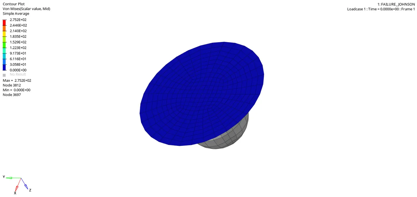
In this simulation, the material card is given as M2_plas_Johns_Zeril with improved shell properties. When the ball hits the plate,the deformation starts and the elements starts to displace, thus a strain will be devoloped.When the ball first touches, we can see that the two elements are getting deleted or removed from the plate.As the deformation increases, the strain energy have been transfered to the adjacent elements. This is because the elements have reached a maximum strain value.When the element reaches strain value of EPS_Max=0.151, then the element will get deleted.
CASE 2:
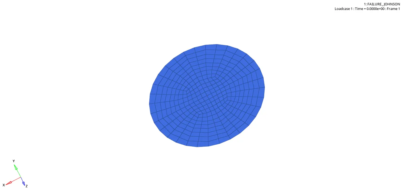
In this simulation, the card image used is the M2_plas_Johns_Zeril with improved and recommended shell properties.In the failure entity card we had changed certain values inorder to check for improved deformation.The values which have changed are as follows:
IXfem=1 : If IXfem is activated, the failure criteria will lead to element cracking by splitting elements into smaller instead of deleting the elements.
IFAIL_SH=1 : This can only be activated if IXfem is activated.In this the shell will get deleted if there is one layer in the failure zone.
Dadv=1 : It is one of the criterian for crack devolopment.
When the simulation is runned, we can see that the much lesser elements are deleted and the strain devoloped is much lower when compared with the Case 1.
CASE 3:
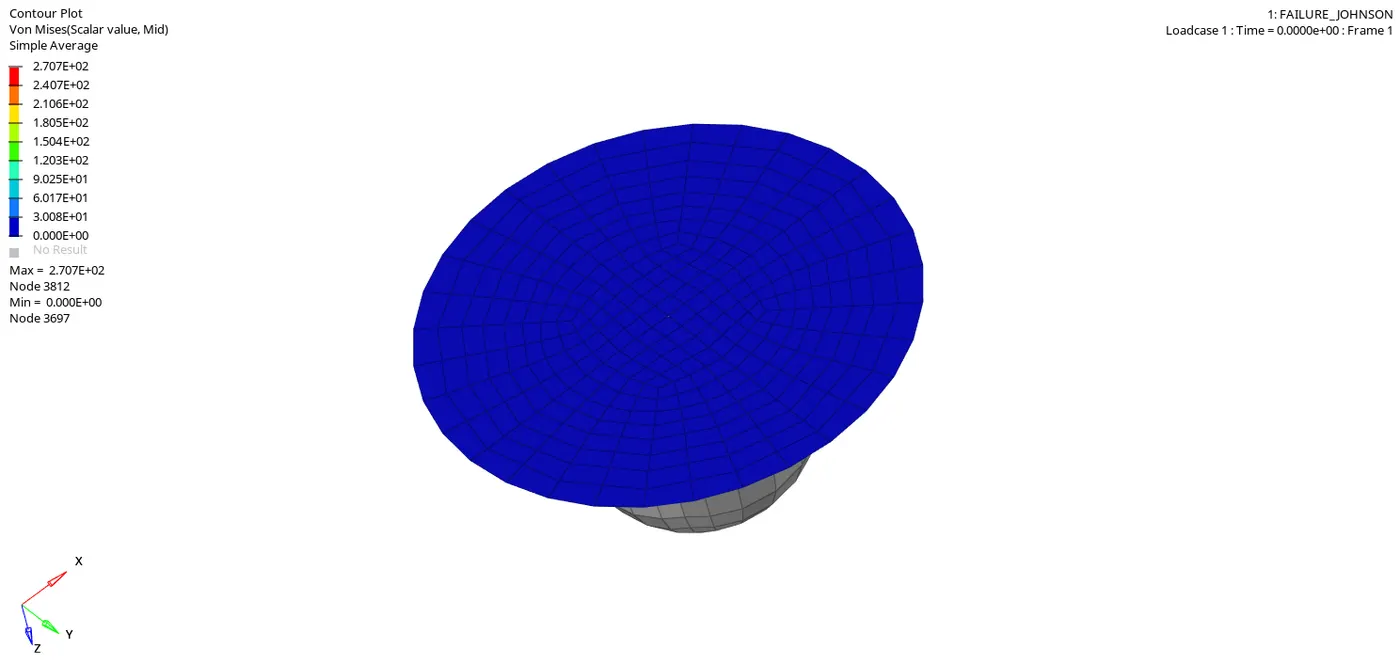
Here in this simulation, the card image used is the Law2 Plasic_Johns with improved shell properties. When the ball hits the plate,the deformation starts and the elements starts to displace, thus a strain will be developed. When the ball first touches, we can see that the two elements are getting deleted or removed from the plate.As the deformation increases, the strain energy have been transfered to the adjacent elements.Since the failure card is deleted so that IXfem and Dadv are zero, element will get deleted rather than getting cracked.Once it reaches the maximum plastic strain value of 0.151 , then the elements will get deleted.
CASE 4:
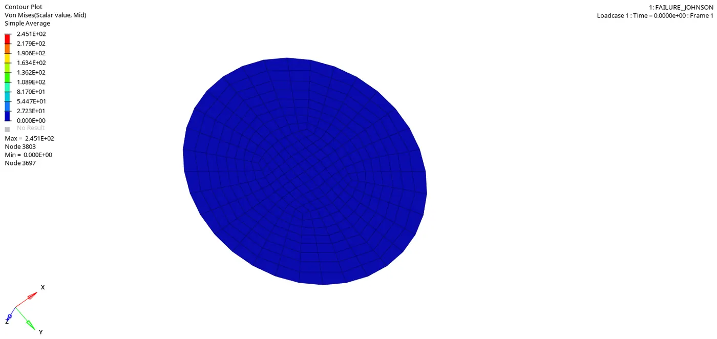
In this simulation, where we neglect the value of EPS_max to zero, so that the criteria for failure is in such a way that the element will only leads to cracking rather than getting deleted.The material card used here is the same as that used before with recommended shell properties.Also the stress formed during the time of deformation is also lesser.
CASE 5:
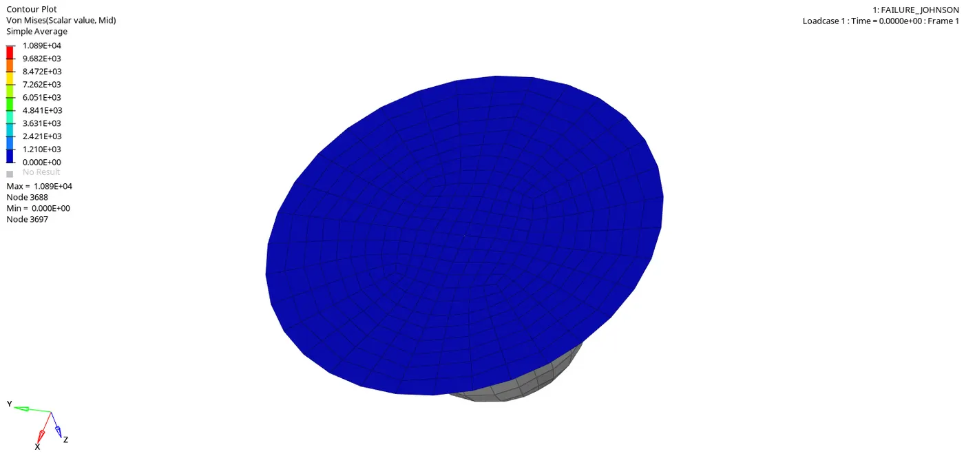
In this simulation,we change the material card from Law 2 Plast_Johns to M1_Elastic. Here the material become Linear elastic. Youngs modules , density and poisons ratio are the 3 factors that determine the material stiffness. So all this factors are within the elastic limit, ie they follow the hookes law. Here the plate is undergoing elastic deformation or reversible deformation, so as a result element will not undergo plastic deformation and the element will not crack.
CASE 6:
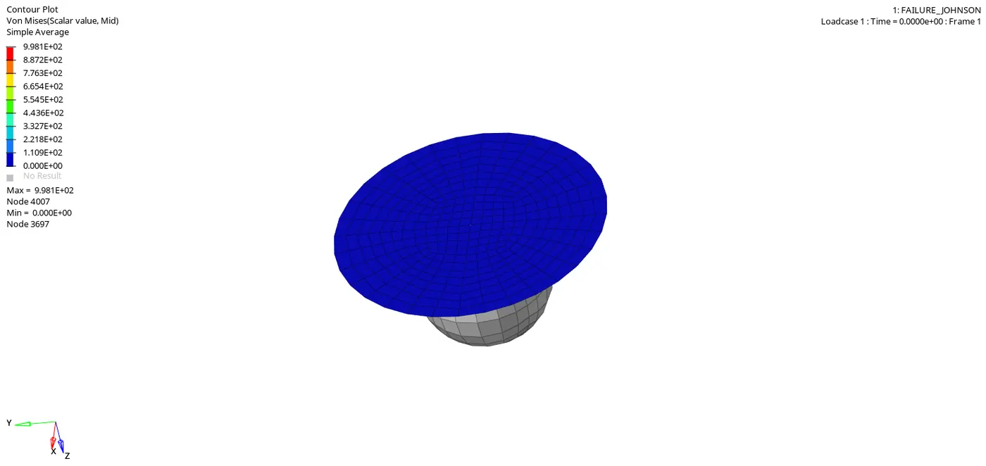
In this simulation, the material card has been changed from Law 1 elastic to Law 36 elasto plastic with the recommended properties. In the material card certain values has to be changed as per given in the question. A curve has to be plotted in this case using the curves card available in the entity tab.With the given values of X and Y, a graph is plotted which will develop a curve which has to be inserted in the material card later. All the recommended input values has to given in the material card.In this simulation, when the ball hits the plate, strain energy is developed and in the later stage, some of the elements are getting deleted.
CASE 7:
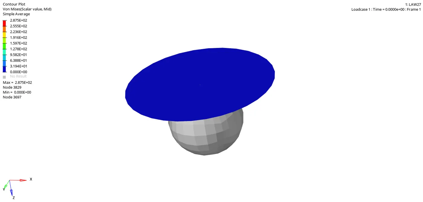
In this case of simulation, the material card has been changed to Law_36, which is Elastic plastic brittle.Eps_p_max is the maximum plastic strain it can achieve, after which the element will get deleted as we can see in the end of the simulation. Eps_t is the beginning of the tensile damage.Eps_m is the end of tensile damage. At this stage, the stress value will be null but the element will not get deleted. Eps_f is the tensile failure , where strain will reach a value and the element will get deleted.
CASE 1:
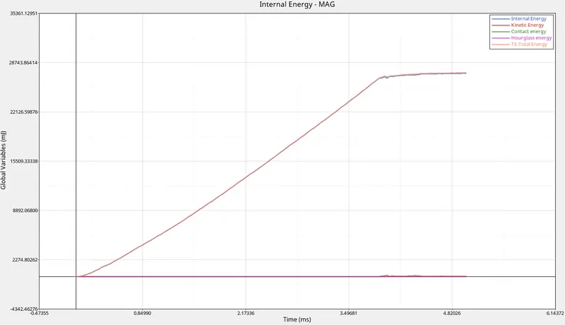
In the first case, the hourglass energy remains constant because the QEPH (IShell=24) recommended property is used in the material card, which removes the hourglass energy with the physical stabilisation method which is controlled in the material level itself.
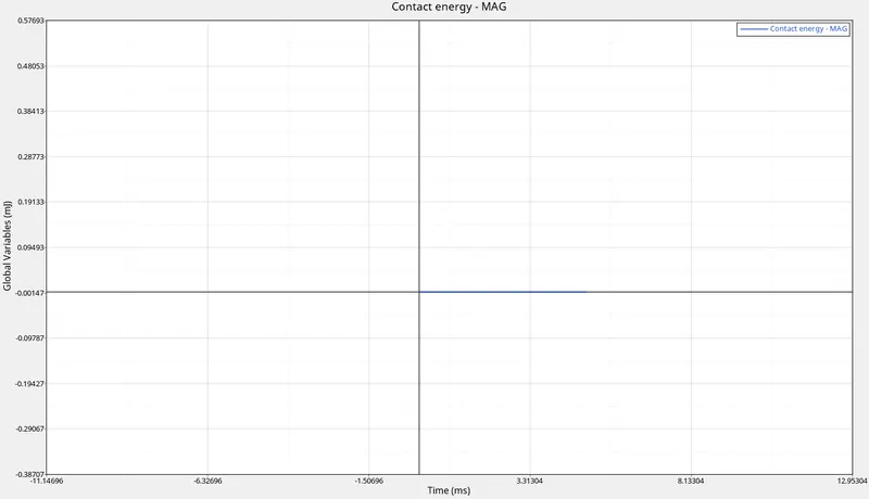
In the case of contact energy, it also remains constant as there is not contact happened due to the deformation of the plate.
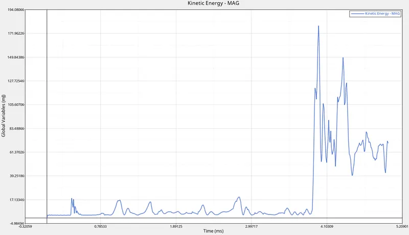
The Kinetic energy and internal energy has a steep hikes at the initial stages as we can see in the graph that at 4.1ms the K.E increases with a sudden increase and then again with the varying deformation, there are some drop and hikes in the graph.As the velocity of the object increases when a force is exerted, the KE also increases. But after the impact in the later stages of deformation, the energy is absorbed from the component, so the kinetic energy varies linearly.This energy is absorbed as internal energy, so that is the reason why it is increasing in small amount.
The total energy is the summation of all the energies formed during the deformation.At first when the component is idle and the total enegy is zero as seen in the graph, but with the initiation of the deformation, the total energy starts to increase and reaches a maximum value.
CASE 2:
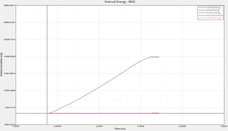
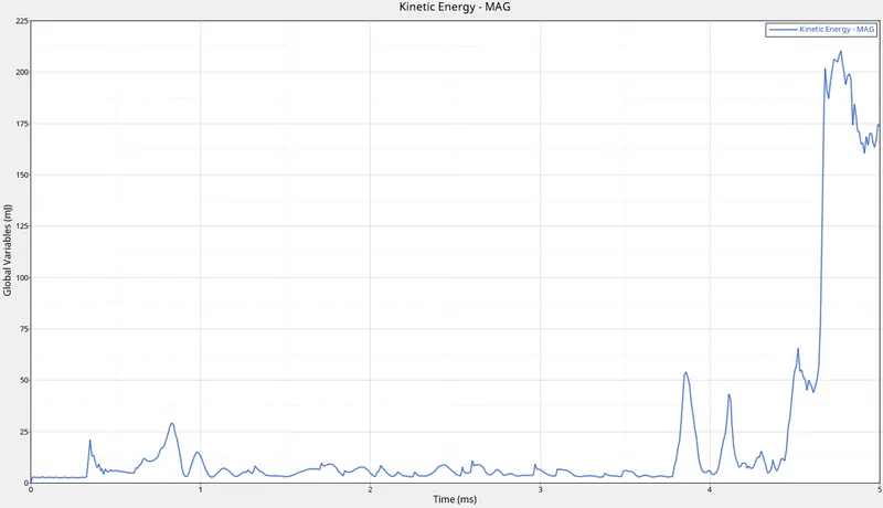
In the second case, the hourglass energy remains constant because the QEPH (IShell=24) recommended property is used in the material card, which removes the hourglass energy with the physical stabilisation method which is controlled in the material level itself.
In the case of contact energy, it also remains constant as there is not contact happened due to the deformation of the plate.
The Kinetic energy and internal energy has a steep hikes at the initial stages as we can see in the graph that at 4.1ms the K.E increases with a sudden increase and then again with the varying deformation, there are some drop and hikes in the graph.As the velocity of the object increases when a force is exerted, the KE also increases. But after the impact in the later stages of deformation, the energy is absorbed from the component, so the kinetic energy varies linearly.This energy is absorbed as internal energy, so that is the reason why it is increasing in small amount.The only thing happened is the variation that happened with respect to time.
The total energy is the summation of all the energies formed during the deformation.At first when the component is idle and the total enegy is zero as seen in the graph, but with the initiation of the deformation, the total energy starts to increase and reaches a maximum value
CASE 3:
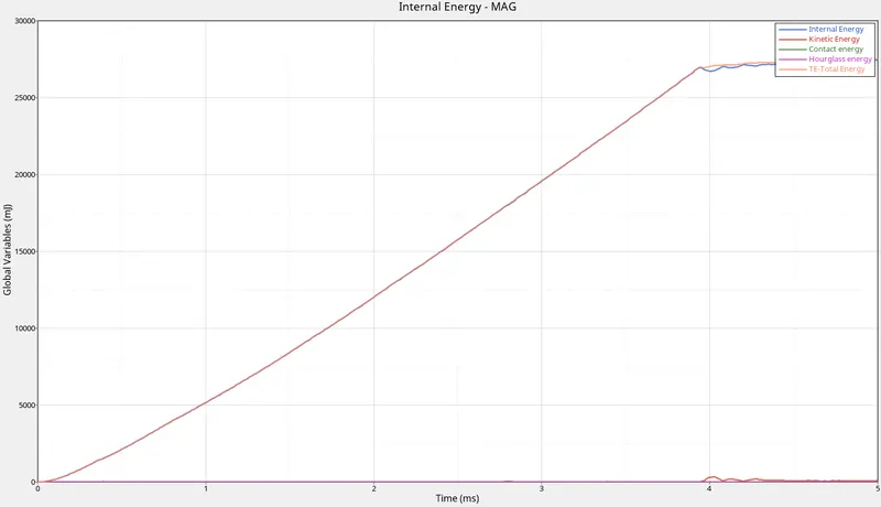
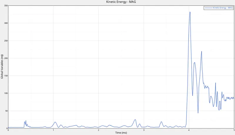
In the third case, the hourglass energy remains constant because the QEPH (IShell=24) recommended property is used in the material card, which removes the hourglass energy with the physical stabilisation method which is controlled in the material level itself.
In the case of contact energy, it also remains constant as there is not contact happened due to the deformation of the plate.
The reason behind the change in Kinetic energy and Internal energy is same as in case 1 and 2. The only difference is the variation of Energy with respect to time.
The total energy is the summation of all the energies formed during the deformation.At first when the component is idle and the total enegy is zero as seen in the graph, but with the initiation of the deformation, the total energy starts to increase and reaches a maximum value
CASE 4:
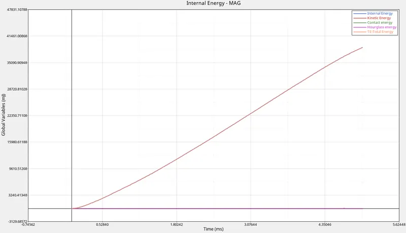
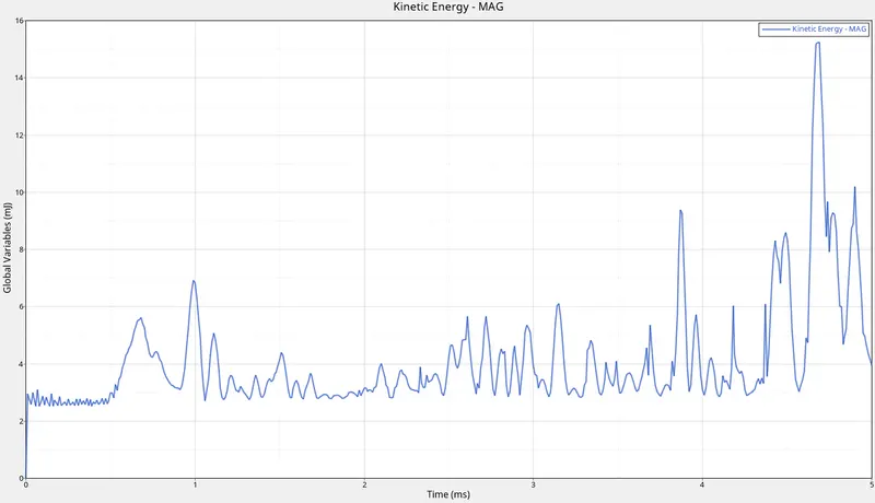
In the fourth case, the hourglass energy remains constant because the QEPH (IShell=24) recommended property is used in the material card, which removes the hourglass energy with the physical stabilisation method which is controlled in the material level itself.
In the case of contact energy, it also remains constant as there is not contact happened due to the deformation of the plate.
The Kinetic energy for this simulation is constant, because from the initial stages of deformation, the kinetic energy is converted into internal energy and the interanal energy varies linearly with respect to time.
The total energy is the summation of all the energies formed during the deformation.At first when the component is idle and the total enegy is zero as seen in the graph, but with the initiation of the deformation, the total energy starts to increase and reaches a maximum value. Here the internal energy and kinetic energy follows the same path and have only very small deviations
CASE 5:
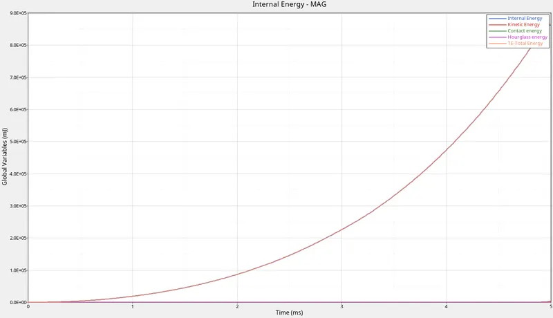
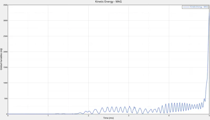
In the fifth case, the hourglass energy remains constant because the QEPH (IShell=24) recommended property is used in the material card, which removes the hourglass energy with the physical stabilisation method which is controlled in the material level itself.
In the case of contact energy, it also remains constant as there is not contact happened due to the deformation of the plate.
The Kinetic energy and internal energy has a steep hikes at the initial stages as we can see in the graph that at 4.1ms the K.E increases with a sudden increase and then again with the varying deformation, there are some drop and hikes in the graph.As the velocity of the object increases when a force is exerted, the KE also increases. But after the impact in the later stages of deformation, the energy is absorbed from the component, so the kinetic energy varies linearly.This energy is absorbed as internal energy, so that is the reason why it is increasing in small amount.
The total energy is the summation of all the energies formed during the deformation.At first when the component is idle and the total enegy is zero as seen in the graph, but with the initiation of the deformation, the total energy starts to increase and reaches a maximum value.
CASE 6:
The hourglass energy remains constant because the QEPH (IShell=24) recommended property is used in the material card, which removes the hourglass energy with the physical stabilisation method which is controlled in the material level itself.
In the case of contact energy, it also remains constant as there is not contact happened due to the deformation of the plate.
The reason behind the change in Kinetic energy and Internal energy is same as in case 1,2,3,5. The only difference is the variation of Energy with respect to time.
The total energy is the summation of all the energies formed during the deformation.At first when the component is idle and the total enegy is zero as seen in the graph, but with the initiation of the deformation, the total energy starts to increase and reaches a maximum value.
CASE 7:
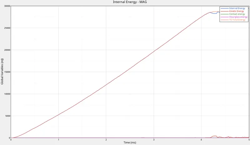
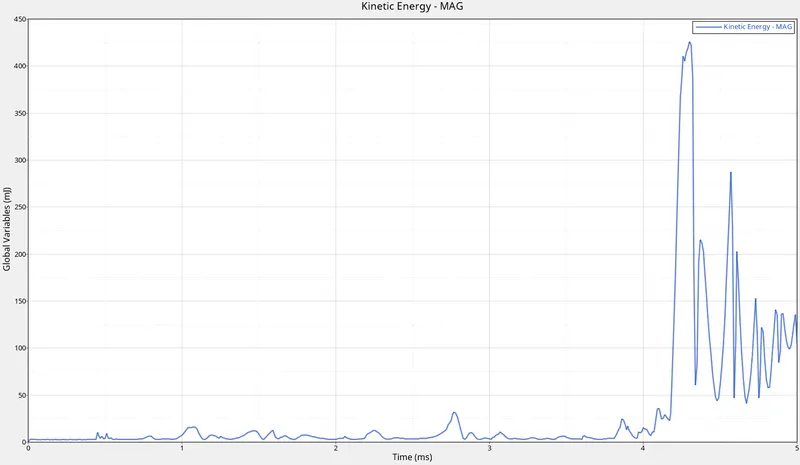
In case of Hourglass energy is constant beacuse Improved shell properties are applied so due to stiffness method it will stabilise the elements and contact energy is also constant.
The reason behind the change in Kinetic energy and Internal energy is same as in case 1,2,3,5 and 6. The only difference is the variation of Energy with respect to time.
In case of Total energy , the component that deforms is at rest and hits by a rigid moving component.. This is why in the graph the Total energy starts at zero and it is changing in the graph when time changes the graph is hiking to a maximum value and after some time the change in Energy is varying.
- Case 6 is used in real life scenario
Law 36- Elastic Plastic piecewise Linear material is the most important material used in industry now.
It determine the proper yield stress number, Failure parametrs and failure properties in plastic region behaviour.
In this law 36, mostly the lab test results are input to the simulation. In lab tests the tests are done at different strain rates. Higher the strain rates earlier the failure.
RESULTS:
All the seven cases are done with simulations and energy plotting.We can see that only in case 5, elements are not getting deleted since the deformation is happening in the plastic region while all other simulation has undergone with plastic deformation with yielding which results in the fracture.During the time of deformation, the elements getting failed and the failed elements are deleted.