Assignment 2
1.
To obtain the speed of sound in a steel rail, we need two unknowns such as Youngs modulus(E) and density(Rho)
These values are available in the Material tab in the Entity bar.
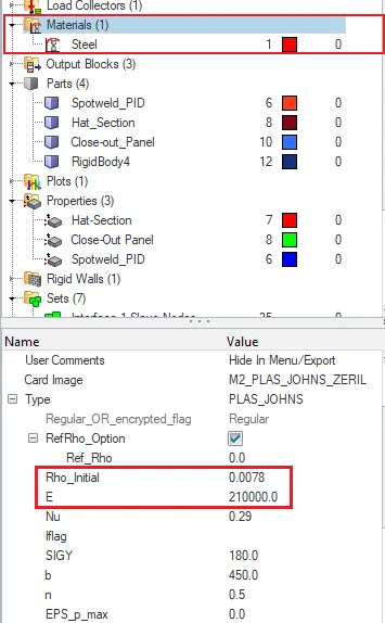
E= 210000 Rho= 0.0078
Speed of the sound(C)= Youngs modulus / Density
= (E/Rho)= (210000/0.0078) = 5188.745 m/s
2. Length of the rail= 1000mm
Time taken for the shockwave to travel from one end of the rail to other= Length of the rail / speed of sound
= ( l/c ) =1000/5188.745
=0.19272ms
3.Time for sound to travel the length of the rail= (l/c)= 0.19272ms
4. The engine file can be edited itself in the Rad file or we can change the values in the hypermesh Engine cards.
- First, change the user profile to RADIOSS
- Import the engine file from the respective file location by using Import->Solver deck->Browse the file-> and click Import.
- In the model browser , select the Card file
- The termination time or Tstop is available in the ENG_RUN file.
- Click on the respective file and change the value of Tstop to 0.19272ms (Given that trmination time equal to the time it takes for the sound to travel the length of the rail)
5.
- Now from the same cards,select ENGINE_ANIM_DT
- We need to find the value of Tfreq.
- Number of Animation steps= 20
- Tfreq = (Tc/No of animations)
= (0.19272/20)
= 0.0096
6.
- NOw from cards, select the ENG_PRINT
- In that ,give the value of N_print as -10 as per given in the question.
7
AIM:
To create the tetra mesh of a housing component and hexa meshing of an arm bracket with the given quality criterias.
PROCEDURE:
- Import the hypermesh model of housing from the file location and analyse the model carefully.
- Clean the geometry wherever there are small gaps in between the surfaces,so that most of the tet-collapse errors can be removed at the earlier stages itself.
- Remove all the minimum and maximum length errors formed by splitting the trias and combining it. The quads formed in the geometry after splitting up can be found using the "By config" tool in the element colour mode tab.
- First the model has to be surface meshed with the 2D mesh using the Automesh(F12) with a target mesh size as 5mm in single shot.
- Once the 2D meshing is complete, move on to the 3d meshing.
- Now the model has to be tetra meshed using 3D->Tetra mesh option by selecting the elements option under the Fixed trias/quads to tetra mesh
- Before that,check whether fill voids,fix midnodes ans smoothing option is checked on in the tetra mesh parameters.Give the tet-collapse value as 0.15
-


- Once it is complete mask few elements to check whether it is formed or not.
- After that check for tet-collapse error in the check elements tab and fix it either by remeshing the geometry using the Tetra remesh option in the Tetramesh panel.
- Remesh the geometry by selecting the elements and click mesh and even if there are more elements to be rectified, then fix the errors manually using the translate option or replacing the points tool.

HEXA MESHING:
- Import the hypermesh model of housing from the file location and analyse the model carefully.
- Clean the geometry wherever there are small gaps in between the surfaces,so that most of the tet-collapse errors can be removed at the earlier stages itself.
- Remove all the minimum and maximum length errors formed by splitting the trias and combining it. The quads formed in the geometry after splitting up can be found using the "By config" tool in the element colour mode tab.
- The component consist of 4 parts: Base, Arm_curve, Arm_straight and Boss.
- First select the base, which has to be surface meshed with the 2D mesh using the Automesh(F12) with a target mesh size as 10mm.
- After which the hexa meshing can be devoloped using the Element offset tool available in the 3D panel.
- Select solid layers option
- First, select the elements which has to be offseted.In along Geom to follow option select the surfaces along the thickness , where the mesh has to be followed.
- Keep the number of layers as 5 and the total thickness as 25 so that 5 layers will be devoloped.
- Click Offset+
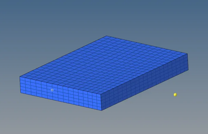
- Now select the 2D shell elements from the base which are needed only for the Arm curve.
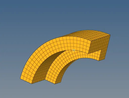
- The hexa meshing in the arm curve can be achieved using the Spin option available in the 3D panel tool.
- Inorder to spin the elements, a center point has to be created using the 3 node distance option(F4).
- Select the elements, Select the axis normal to which it has to be rotated, here in this case being X-axis, and the base point as the centre node, the angle in which elements to be rotated is 90 degrees.In the On spin option type the numner of layers needed in between the model. click spin+ or spin- accordingly.
- The next part in this model is the arm straight which can be hexameshed using the Linear Solid option available in the 3D panel.
- For the element selection, it has to be shell elements and the shell elements of the arm curve has to extracted. Fot that go to Tools-> Faces-> Select the components-> Find faces.
- So the elements have been created in the first base. In the second base do a 2D shell mesh, so that number of elements formed should be exactly same as that of the first base.
- In the Linear solid there is From and To option available.Select the elements in the arm curve base as from and elements on the other end of arm straight as to.The alighment has to be given exactly as what is given initially for the first elements selected from the arm curve.
- Click on solids and a proper hexa mesh will be formed on the arm_straight part.
- The last part is the Boss, which can be Hexa meshed with the Solid map option available in the 3D panel.
- First, one side or base of the cylinder boss has to be shell meshed.
- In the source geometry. select it as none.In the elements to drag option, select the 2D shell elements from the base. In the desination Geom select the oppposite base of the boss cylinder. To give the path by which mesh has to go, in teh alon Geom select the node path as shown above and in line, select any straight line ie. going along the path.
- Give the size as 10mm and click mesh.The Hexa mesh will be devoloped accurately in the boss with proper connectivity.
(NOTE: Whenever starting with a part,change that part to the current model,so that mesh will be stored in that respective part itself.)
- Now delete all the Quad4 elements from the model using the delete option and selecting the By Config option.
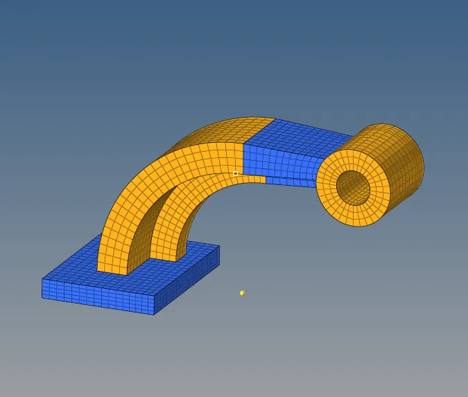
RESULTS:
- All the calculations are done and changes have been made in the engine cad file which are written above and are updated in the hypermesh file
- The components have been tetrameshed and Hexameshed with the given target length and have been removed with all tet-collapse.