Assignment 3
OBJECTIVE:
1. Run the crash test of the given beam with a wall , with existing properties.
2. At the end of the simulation, do the energy error and mass error checks.
3. Plot rigid wall forces, internal energy, hourglass energy, contact energy, total energy and kinetic energy of the simulations.
4. Also do the crash test with Recommended properties as per given in the question.
5. Check energy error and mass errors for the same, Also plot the energy graphs as first case.
6. Compare between both cases.
PROCEDURE:
1. Open the hypermesh software in the Radioss user profile as we are doing an explicit solver analysis.
2. Import the .rad file using Import->solver deck->and browse for the file from the respective file location.Click Import so that the model will be available in the graphics panel.
3. In the model browser, click on Card.
4. Under Card, select the ENG_RUN, where change the value of total run time (TSTOP) as 55ms as given in the question.
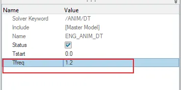
5. As same, under the card,select the ENG_ANIM_DT and change the value of TFREQ to 1.2,as per the calculation when the number of animations initially given as 46.
6. After all the Engine files has been edited, now we can start with the analysis by going to the Analysis panel in Hypermesh tool.
7. Click on Radioss and a tab will be opened.Select the input file location where you have to save the model, export option as ALL, run option as Analysis and run number as 1.In the option column, type -nt 4 to run the results much faster.
8. Then the software wil run the analysis ans shows the result.After computation is over, close the pop-up tab and change the panel to Hyperview panel.
9. In this panel, upload or browse for the .h3d file which is the animation file created for the respective model which shows the deformation happened when it srrikes a Rigid wall.
10. Split the screen into two so that the graphs which will be opened can be seen in the other half of the graphics panel.
Plotting Rigid wall forces and Global Variables
1. From Hyperview, change it to Hypergraph 2D, which allows us to plot the graphs.
2.When it is opened, a new panel will be opened at the bottom where upload the Input file of .T01(which shows the Time history plots).
3. Below that we can see the X Type and Y Type which is nothing but the X component and Y component.
4. On X axis, select the time as the constraint while in the Y axis, it is subdivided into three:
- Y Type
- Y Request
- Y Component
5. In Y type, select Global variables.
In Y Request, select the energy constraints which we need.Here we took Kinetic energy,Internal energy,Hourglass enerfy,Contact energy and Total energy for consideration.
In Y Component, select the MAG OPTION. Click Apply.
6. Similarly, we plot another graph for Rigid wall forces which is the resultant normal and tangent force and the total resultant force.
7.The simulation can be runned using the animation file which have been uploaded earlier. Click on the model which has been opened in the Hyperview panel(as we have already uploaded the .h3d file).Click on the play button and now we see the animated video of the model with deformation when striked on to a rigid wall.
8.If we need to see all the deformation in terms of displacement or velocity with the intensity of deformation happening at each sections, then there is an option called Contour, which is available in the bottom menu bar.

9. When clicked on it, a new panel will be opened where select the result type which you need ie. displacement, velocity etc.Next select the component which you need to be contoured.
ENERGY AND MASS ERROR CHECK:
Energy error: The Energy error is computed in radioss as percentage.
- If the error is negetive , then there is some energy dissipated.The normal hourglass energy is about -10% to -15%.
- If the error is positive,then tehre is some energy creation.Error of +1% or +2% is acceptable.When positive there wont be any hourglass energy and the computated results will also be much accurate.
CASE 1: WITH ALREADY EXISTING PROPERTY:
In the file folder we have 0001 file which has to be opened in notepad and check for the values of energy and mass error

The value or percentage of energy error for this model is -10.3% which is acceptable and the Mass error has a value of 0.1659 E-03. Since the mass error has to be less than 5% of the total mass of the model.Since it is way below 5%, then the mass error values are acceptable.
CASE 2: WITH THE RECOMMENDED PROPERTY:
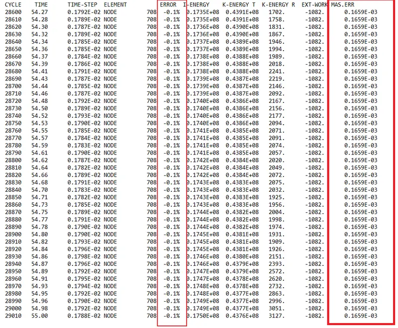
- Here i got -0.1% so its acceptable in case of QEPH ie.full integration formulation where the hourglass will be zero as the QEPH has physical stabilization to remove hourglass in the material level itself.
- For Mass error, it should be less than 5% of the total model mass.
- Our mass error is 0.1659E-03 which is less than 5% of the total mass so its also acceptable.
SIMULATION ANALYSIS WITH GLOBAL VARIABLES AND RIGID WALL FORCES :
CASE 1: WITH ALREADY EXISTING PROPERTIES
1. In this case, the model has it own default properties without any change in it.
2. The animated simulation with the default property values are shown below:
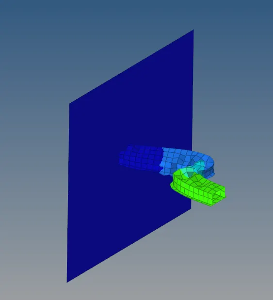
Here the beam is crushed on towards the rigid wall.The above figure is displayed with repect to displacement with the contour. We can see that the elements at the initial deformation areas have been displaced much higher awway than the elements near the rigid wall.
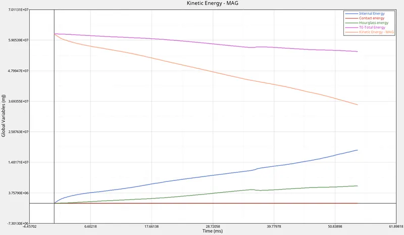
- Kinetic Energy: The kinetic energy of this model starts with a very high value from the initial stage (5.9E+07) and then gradually decreases.This is because at the initial stage of deformation happens with very high velocity and with applies mass of the body.But with time, when the force moves along the surface some energy will get disscipated along the path.So there will be slow decrement in the value of kinetic energy.
- Internal energy: It is the sum of kinetic energy and potential energy.when t=0 , the internal energy is zero as there where no deformation happening currently.But when the deformation starts, frictional force is devoloped along with some heat dessipation.With the intensity of deformation, the internal energy will be increased.
- Hourglass energy: Since the IShell properties of the model is IShell=0 by default and it is in underintegrated shell elements.In this under-integration only one point will be there for the elemental calculations where the force and displacements exist in each 4 nodes of the element.The summation of displacements and force sometimes provide zero strain and stress values and then the element fails to calculate the stiffness values.When it fails in such a way, it will result in some weird deformation and results in the formation of hourglass energy. Thus here also the body is deformed little without any stress and by time this deformation goes on increasing so the graph of hour glass is increasing.
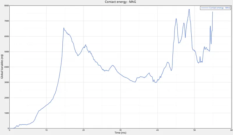
- Contact energy:This type of energy is formed when one element comes in contact with the other or neighbouring elements.The opposing force created by this element forms the contact energy.At the first stages of deformation, the contact energy goes constantly without any increase. But at the half section,with the bending or high deformation take place, the contact energy will be devoloped and increases gradually and reaches a maximum value.After the helf section the deformation is reduced, so there were no high contact with the elements then the contact energy will be reduced. But in the above graph with all energy plotted in a single graph, the contact energy tends to form negligible.
- Total energy: The total energy of the system is the summation of all the energies happening with the component.The total energy is always conserved but the other energies like K.E is not conserved.Kinetic energy is very high at the initial stage due to the initial high velocity and the mass of the body applied to it.When the deformation starts, K.E is reduced and the internal energy is increased and the contact energy here is negligible.So the total energy will become constant at a value of 6.2E+7.But with the formation of hourglass energy ,the total energy will be reduced to a value equal to the increase in hourglass energy.That is the reason why the total energy is getting reduced from that value.
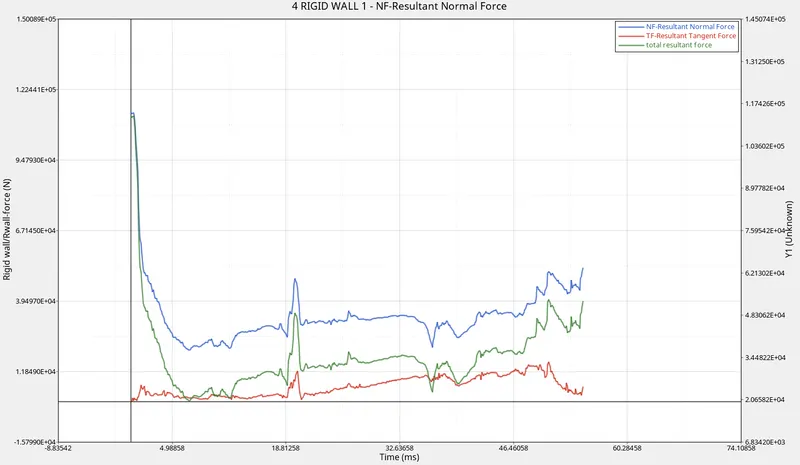
- Resultant normal force:The normal force is the force acting normal to the body.At the initial stage the resultant normal force have a very high value of 9.9E+4. This is because when the foce is applied to the model.it strikes the rigid wall with very high velocity.This is the reason why it starts with a high value at the initial stage of deformation.After which the intensity of deformation reduces and when it reaches the half stage, then again there is a slight increase in the value as the deformation or the bending is higher at this stage and with the succesive stages it shows some high and low peaks due to this.
- Resultant Tangent force: This is the force acting tangent to the body. The tangent force is similar to the frictional force.at start without any contact the resultant tangent force will be zero and minimally varies with time.
- Total Resultant Force: It is the sum of resultant normal and resultant tangent force.So when combined together it will plot a graph similar to the normal and tangent force.
CASE 2: WITH RECOMMENDED PROPERTIES:
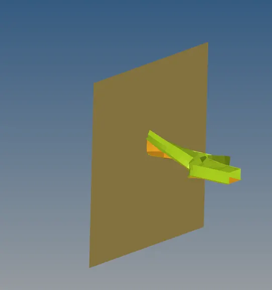
The below shown animation is the model with recommended properties applied.We can see that the model is not only getting deformed but also getting twisted along its path.
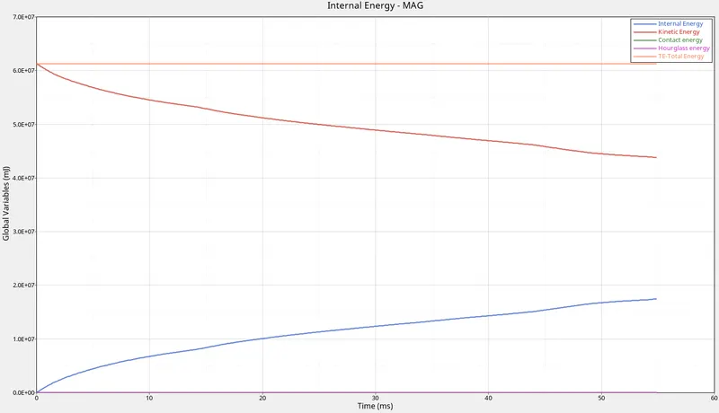
- Internal energy: It is the sum of kinetic energy and potential energy.when t=0 , the internal energy is zero as there where no deformation happening currently.But when the deformation starts, frictional force is devoloped along with some heat dessipation.With the intensity of deformation, the internal energy will be increased
- Kinetic Energy: The kinetic energy of this model starts with a very high value from the initial stage (5.9E+07) and then gradually decreases.This is because at the initial stage of deformation happens with very high velocity and with applies mass of the body.But with time, when the force moves along the surface some energy will get disscipated along the path.So there will be slow decrement in the value of kinetic energy.
- HourGlass Energy: In Ishell 24 , physical stiffness is used to remove the hourglass energy in the material level itself and extra stiffness is added in the property level to remove the extra deviation of the nodes, which will remove the total accumulated hourglass deformation. So here the hourglass energy is vanished due to the use of Ishell 24, Here the stiffness is added in a way that no hourglass energy is produced.
- Total energy: The total energy of the system is the summation of all the energies happening with the component.The total energy is always conserved but the other energies like K.E is not conserved.Kinetic energy is very high at the initial stage due to the initial high velocity and the mass of the body applied to it.When the deformation starts, K.E is reduced and the internal energy is increased and the contact energy here is negligible.So the total energy will become constant.Since the QEPH element formulation is used, the hourglass energy is zero and that is why the total energy remains constant throughout without any deformation.
- Contact energy: It is formed by the contact of the two bodies . Here we can see that there is no formation of energy on the rigid wall while colliding of 2 bodies that is why the contact energy is zero.
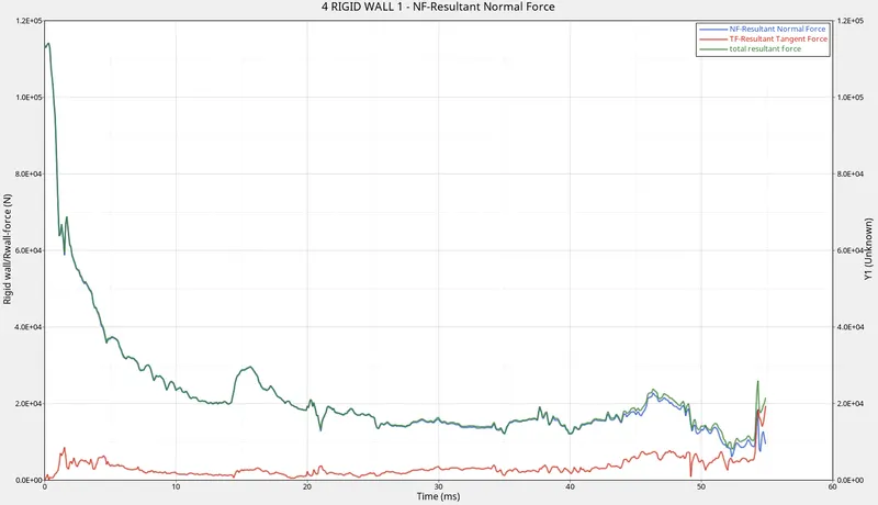
- Resultant normal force:The normal force is the force acting normal to the body.At the initial stage the resultant normal force have a very high value of 9.9E+4. This is because when the foce is applied to the model.it strikes the rigid wall with very high velocity.This is the reason why it starts with a high value at the initial stage of deformation.After which the intensity of deformation reduces, the value will be reduced.As compared to the first case, there is not much bending in between the model and the deformation is much lesser as compared to the first case.That is why the the graph of resultant normal force is reducing without any increase.
- Resultant Tangent force: This is the force acting tangent to the body. The tangent force is similar to the frictional force.at start without any contact the resultant tangent force will be zero and minimally varies with time.
- Total Resultant Force: It is the sum of resultant normal and resultant tangent force.So when combined together it will plot a graph similar to the normal and tangent force.
RESULTS:
The given beam is analysed in the radioss and the graph is plotted before and after adding the recommended properties which is analysed and explained.