Week 4- Challenge
AIM:
Create 1D elements with given cross-section and DOF on a bracket design model inorder to make it stiff and rigid.
The one dimensional elements used in this model are RBE2, RBE3, CROD, CBEAM, CBAR AND CELAS.
PROCEDURE:
- Import the IGS model from the file using import tool.
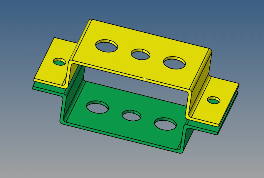
- Analyse and check the model for triple cons and if needed, do an autocleanup.
- Next step is to create the midsurface of the model, which is done by taking the mid for each part named as bracket_1 and bracket_2.
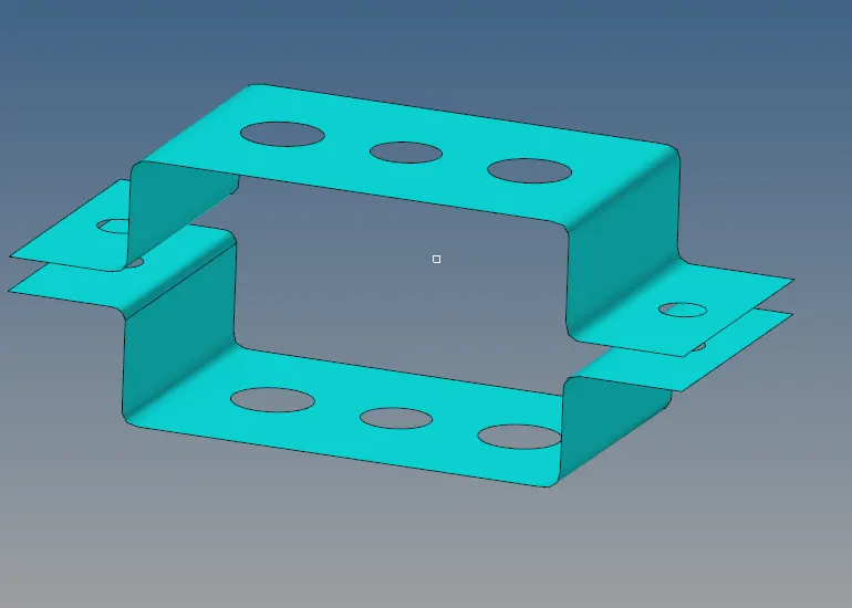
- Once the mid surface of bracket_1 is extracted create another new component and make it as current before extracting the secong mid surface.Organize is a tool which allows to move or copy any files from one place to another.

- The mid surface can be taken by the midsurface tool in geometry tab. Select the automid as the option and select the surface which here has to be meshed and click extract. Likewise, the mid of bracket_2 also has to be extracted.
- Next step is to delete the surface of the brackets.This is done by selecting the delete option in the toolbar and delete the surface by window selecting the whole model.Also, in the Model view delete the surfaces and wireframes from the components tab.
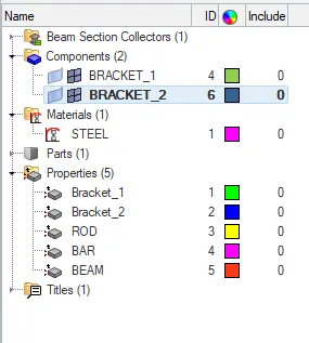
- In the browser tab create the material by right clicking create->material.Change the material of the bracket as Steel and also define the card image respectivily.
- After which we have to create the properties for bracket_1 and bracket_2 and in each of that add the material and thickness to it.The thickness of bracket_1 is 2 mm and bracket_2 is 2.5mm.
- Now we have to update the components tab by adding the property that we have made or devoloped for each of the brackets in the property tab.
- After all these updations have been done, next step is to move to the meshing scenario before which washer split have to be drawn around the holes which is in the quick edit option in the geometry toolbar.
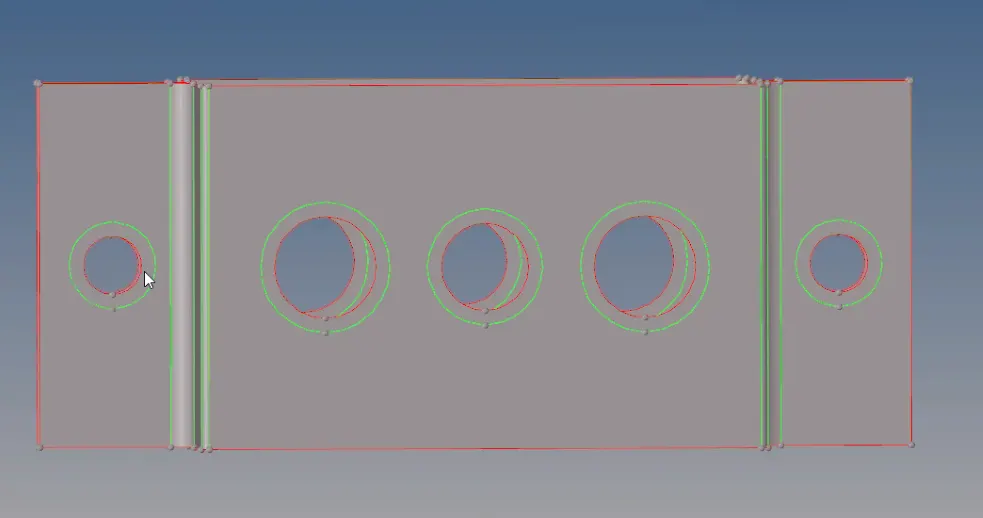
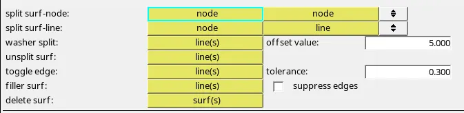
- In the 2D toolbar, select the automesh and select the surface which have to be meshed (choose all or displayed), select the element size as 8 and mesh type as mixed and mesh the component. The meshing may take a bit longer depending upon the complexity of the component.

- After the mesh is created ensure that the boundary edges of the holes where the washer splits are given are of equal number of nodes and no trias are formed at the boundary edges.
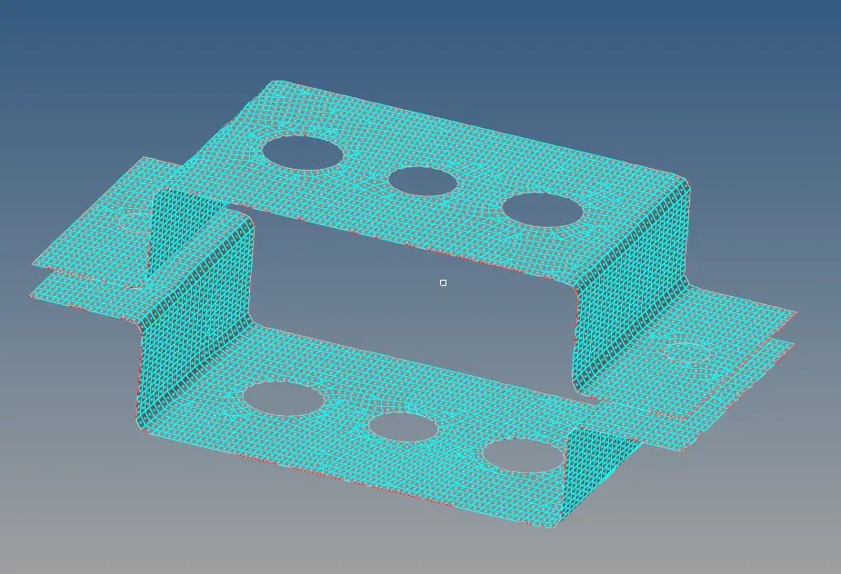
- Now the holes have to be rigidised with the RBE2 as well as RBE3 connections as given in the question with the required degree of freedom.
- The RBE2 connection can be devoloped using the rigids option in the 1D toolbar. The RBE2 have multiple dependent nodes and single independent nodes while the RBE3 have one dependent node and multiple independent node.

- In the rigids,select the independent node as nodes and select the path option to select the nodes easily and give the DOF as per the given question and click create.

- For RBE3 elements,select the nodes just opposite to RBE2 node selection and select the DOF as per required and click create.
- After creating RBE2 link on d & e ,apply mass on the nodes by selecting the masses on the 1D toolbar and select the nodes where to apply the mass ang give the value in the column specified. Ensure that the element type is given as CMASS1.

- Next we have to create the cross sections for this bar, rod and beam as Cross, Thin walled box, I-section respectivily. Generate all the cross section with the given values as dimensions.Ensure that the names of the C/S have been changed to element name.This is done on the Hyperbeam View on the toolbar next to the model view.
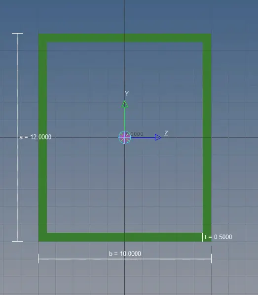
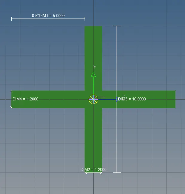
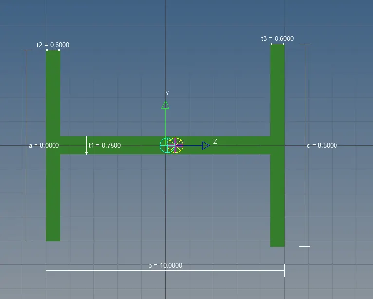
- Open the hyperbeam view and in the entities add the required C/S as given in the question by right clicking on the tab and select Create->Standard section->Optistruct or Hypermesh.You will get the C/S either from these two options.
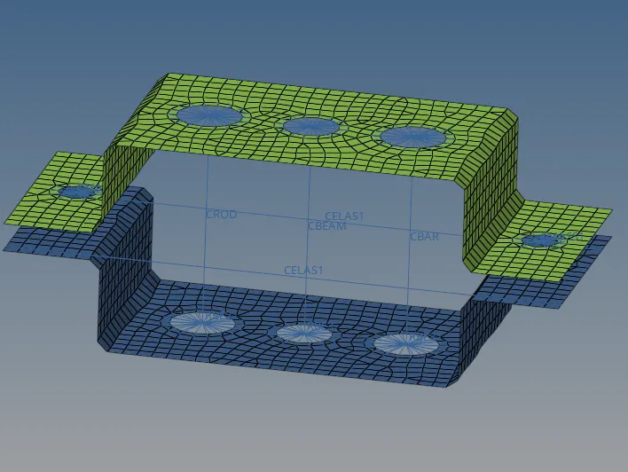
- After creating the cross section, the 1D elements have to be generated like bar,rod and beam connecting the two links.
- The bar and beam can be created using a single tool where just the options has to be changed.In the 1D toolbar we get the bars option.In that select the nodes A and B, select the path where it has to be formed and select the element type as CBAR and bar is formed.
- Likewise Beam can also be created by selecting the nodes and select the path and selecting the element type as CBEAM.
- The Rods can be created with the rod option in the 1D. Select the nodes and select the element type as CROD.
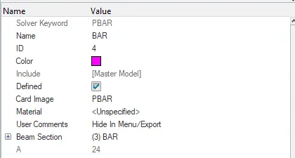
- Now create properties for bar,rod and beam in the property tab. In the detailed property tab pop up below, change the card image as PROD,PBAR and PBEAM respectivily and in the beam section column add the cross section that has been created earlier in the hyperbeam.
- After all these properties are updated with the hyperbeam cross section,then go to each 1d toolbar to update the property tab.In all the rod, bar and beam option update the property tab with the respective property that we have created earlier.By doing that all the properties get updated with the hyperbeam section that it has been converted into a solid.
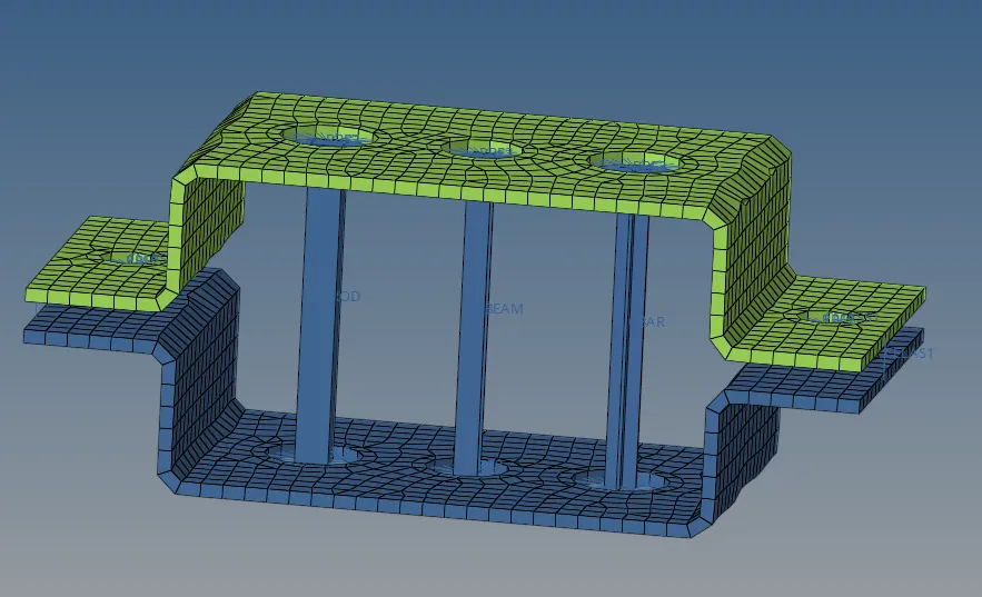
- For example in the case of bar, select the bar option, in there select the update option and select the element , select the path and in the next tab shown as property, click on it and select the bar property that we created in the model view table and select the element type as CBAR and click update.Likewise it has to be done for rod and beam.

- Now inorder to change the view from 1D to 3D, just change the view from one Dimensional traditional element to 1Dimensional detailed element view in the toolbar.
- So this helps to see our connections in 3D.

- Now the last connection is the spring connection which has to be given at edges of f as shown in the figure.This can be done using the springs options in the 1D toolbar. Select the nodes on the edges and since it will be formed in the translational x axis it automatically constraints DOF1.The element type here is CELAS1.Then the spring connection is formed along the required path.

- Inorder to make the surface solid from 2D, just select the option from 2D Traditional element rep to 2D detailed element representation.
CONCLUSION:
The two unattached brackets of uniform thickness has been meshed by extracting the midsurface out of it and thereafter rigidize the material by giving RBE2 and RBE3 connection links on all holes and in between links rod,beam and bar connections have also been created with the given dimensional values.