Assignment 5
OBJECTIVE:
- Create the mesh for bumper assembly with a mesh size of 6mm.
- Run the crash tube model as it is.
- Change the property to Inacti=6 and run the model.
- Create the type 11 contact with the dafault values and run the simulation.
- Remove both notches from the tube and remove boundary condition on rigid body nodes then run.
- Create a new notch in the middle ,select the whole section and run.
- Create a new notch with nodes only from opposing 2 faces and run.
With the above formed simulation results,
1. Plot RWALL forces ,contact forces,internal energy and Create TH/PART for all parts and compare results for all cases.
2. Comment your thought on why there is a change in the internal energies.
3. How does the notch affect the results?
4. Plot energies and note any difference.
PROCEDURE:
BUMPER ASSEMBLY:
1. First, import the model of bumber assembly from the file location.
2. Check for any surface deformation and if any, remove it.
3.Align the flanges to a distance as per the temporary nodes given. This can be done using the translate option available in the Tools panel.
4. After aligning all nodes to the respective positions, extend the flanges to the surface using the extend option available in the surface edit toolbar.
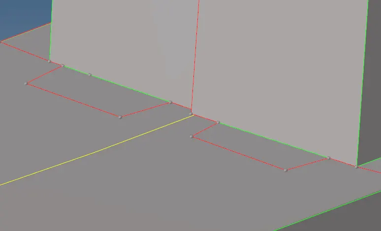
5. After all the clenups in the geometry has been finished, go for meshing of the component which can be done using the Automesh option available in the 2D panel.
6. Select the surafce to be meshed andchange the element size to 6mm and check the options of Align and Size. Click mesh.
7. The completed model of mesh is given below:
8. After which rigid connections a=have to be given in between the flange and the base surface wherever the connections are not formed.
9. Inorder to give rigid connection goto Rigids in the 1D panel.

10. In this panel select the nodes which has to be rigidized with all the DOF constrained and click create. The rigid element will be formed in between the nodes.
CRASH TUBE SIMULATION:
CASE 1:
1. Open the Hypermesh in Radioss user profile.
2. Import the model in Solver deck and click import.
3. The first case implies to run the model as it is ie. with the given default value.
4. By defualt, the interface is in Type 7 ie, the node to surface interface contact. The gap is defined aroung the master and slave segment and this gap can be variable or constant. The slave is kept outside the master with the help of resistive forces.
Here the Igap=0(determines how the size of the gap is calculated) and GApmin=1(minimum gap needed for the activation of the interface) by default.Since the distance between the master and slave is more than gapmin value, the initial penetration or th penalty formulation will not be formed.
The graph for each component has also to be plotted which can be done by opening the solver deck entity. Under that open the TH file and under that create a part within it.In the pop-up menu, for the Entity ID select all four components and select the required variables needed to be plotted for each component and in the next Data:part, select the variables needed. Here the selected variables are IE, KE, HE and TE.
5. Run the simulation by going to the Radioss in the Analysis panel.Browse the location to which the simulation fiel has to be saved.
6. Check the export option have been turned to All, Run option as analysis and the run number as 1. In the option type-nt 4 to increase the speed of the simulation. Click on radioss.
7. At this time, the simulation starts to run and it may take a while longer,depending upon the model.
8. Change the hypermesh panel to Hyperview panel and browse the animation file from the previous saved simulation result. The Anim file will be in .h3d format.Click apply.
9. The animation file with the crash tube hitting the rigid wall will be devoloped.
10. Now split the window and open the Hypergraph 2D panel.
11.In the same simulation file check for T01 file and upload it in the Hypergraph.
12. Below that we can see the X Type and Y Type which is nothing but the X component and Y component.
On X axis, select the time as the constraint while in the Y axis, it is subdivided into three:
- Y Type
- Y Request
- Y Component13. In Y type, select Global variables.
In Y Request, select the energy constraints which we need.Here we took Kinetic energy,Internal energy,Hourglass enerfy,Contact energy and Total energy for consideration.
In Y Component, select the MAG OPTION. Click Apply.
14. Similarly, we plot another graph for Rigid wall forces which is the resultant normal and tangent force and the total resultant force as well as the graph to be plotted for each component or part seperetely.
15. Below are the graph plots which has been plotted:
(i) Global variables:
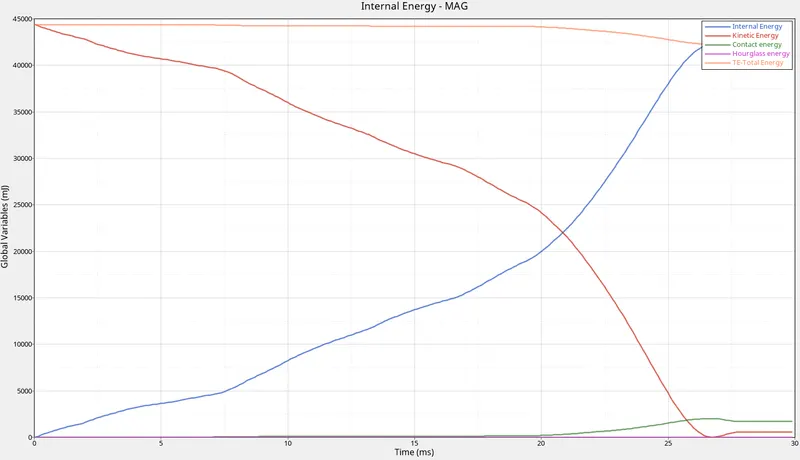
This plot shows the variation in energies.
- Kinetic Energy: The kinetic energy of this model starts with a very high value from the initial stage (5.9E+07) and then gradually decreases.This is because at the initial stage of deformation happens with very high velocity and with applies mass of the body.But with time, when the force moves along the surface some energy will get disscipated along the path.So there will be slow decrement in the value of kinetic energy.
- Internal energy: It is the sum of kinetic energy and potential energy.when t=0 , the internal energy is zero as there where no deformation happening currently.But when the deformation starts, frictional force is devoloped along with some heat dessipation.With the intensity of deformation, the internal energy will be increased.
- Hourglass energy: Since the IShell properties of the model is IShell=0 by default and it is in underintegrated shell elements.In this under-integration only one point will be there for the elemental calculations where the force and displacements exist in each 4 nodes of the element.The summation of displacements and force sometimes provide zero strain and stress values and then the element fails to calculate the stiffness values.When it fails in such a way, it will result in some weird deformation and results in the formation of hourglass energy.Since the Ishell is given as QEPH 24 is applied in the property tab, the hourglass energy is reduced to zero with the physical stabilization happening in teh material level itself.
- Contact energy:This type of energy is formed when one element comes in contact with the other or neighbouring elements.The opposing force created by this element forms the contact energy.At the first stages of deformation, the contact energy goes constantly without any increase. But at the end of the simulation, with the high deformation or crushing happens, the contact energy will be devoloped and increases gradually. But in the above graph with all energy plotted in a single graph, the contact energy tends to form negligible.
- Total energy: The total energy of the system is the summation of all the energies happening with the component.The total energy is always conserved but the other energies like K.E is not conserved.Kinetic energy is very high at the initial stage due to the initial high velocity and the mass of the body applied to it.When the deformation starts, K.E is reduced and the internal energy is increased and the contact energy here is negligible.So the total energy will become constant.But with the formation of contact energy ,the total energy will be reduced to a value equal to the increase in contact energy.That is the reason why the total energy is getting slightly reduced from that value.
(ii)R-WALL Graph
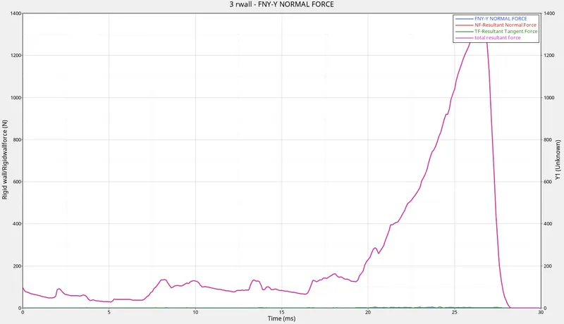
- Resultant normal force:The normal force is the force acting normal to the body.At the initial stage the resultant normal force starts with a low value. This is because at the initial stage the deformation happened is less and it strikes the wall with less velocity. After which the intensity of deformation reduces and when it reaches the half stage, then again there is a slight increase in the value as the deformation or the bending is higher at this stage and reaches a maximum value and drops back to zero.
- Resultant Tangent force: This is the force acting tangent to the body. The tangent force is similar to the frictional force. At start without any contact the resultant tangent force will be zero and minimally varies with time.
- Total Resultant Force: It is the sum of resultant normal and resultant tangent force.So when combined together it will plot a graph similar to the normal and tangent force.
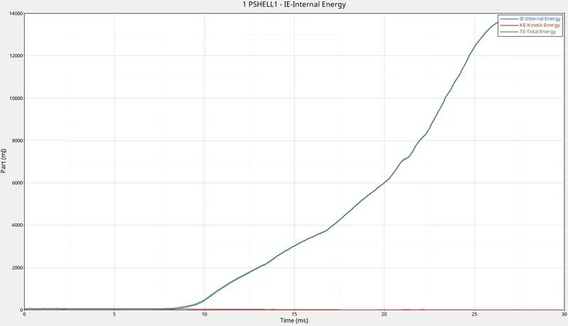
(iii)Part/TH
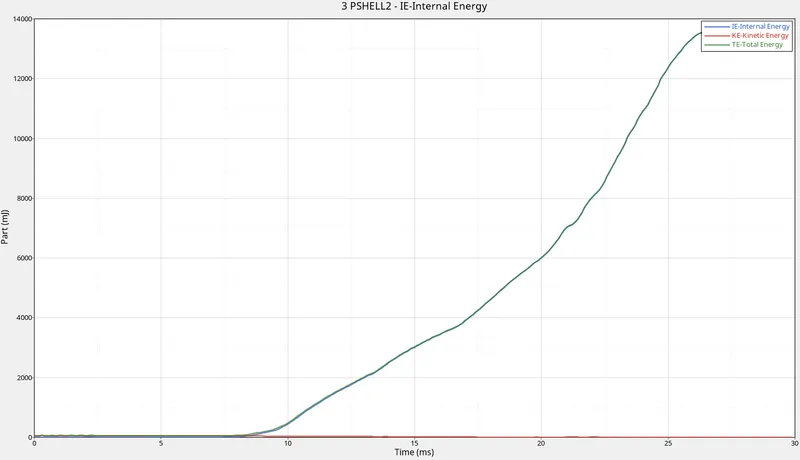
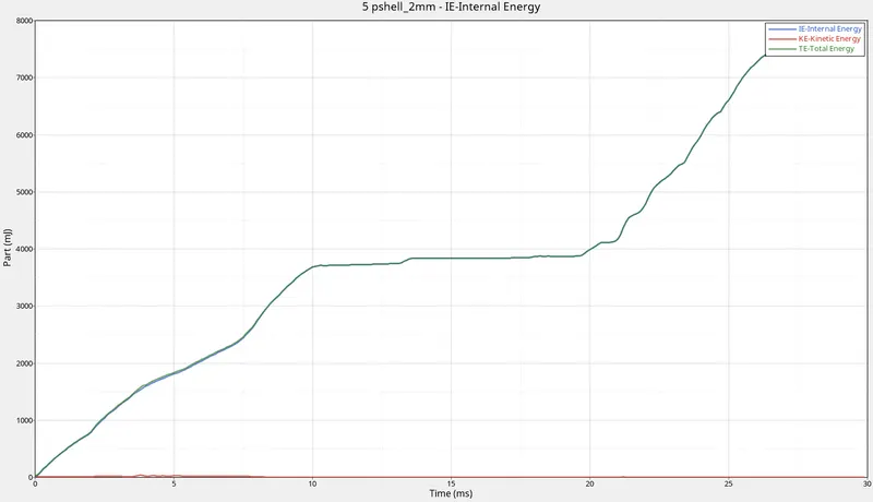
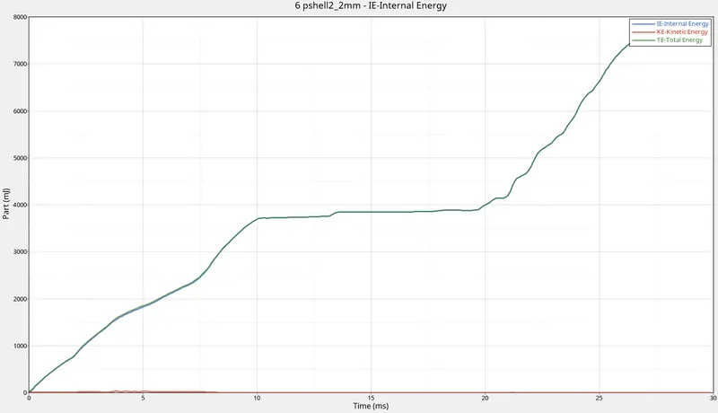
16. The animated simulation result for case 1 is shown below:
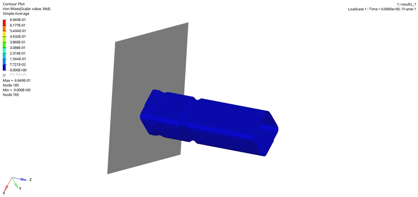
CASE 2:
1. Open the Hypermesh in Radioss user profile.
2. Import the model in Solver deck and click import.
3. The first case implies to run the model by changing to Inaci=6. The inacti property can be changed in the groups file in the model entity.
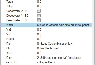
4.
By defualt, the interface is in Type 7 ie, the node to surface interface contact. The gap is defined aroung the master and slave segment and this gap can be variable or constant. The slave is kept outside the master with the help of resistive forces.
Here the Igap=0(determines how the size of the gap is calculated) and GApmin=1(minimum gap needed for the activation of the interface) by default.Since the distance between the master and slave is more than gapmin value, the initial penetration or th penalty formulation will not be formed.
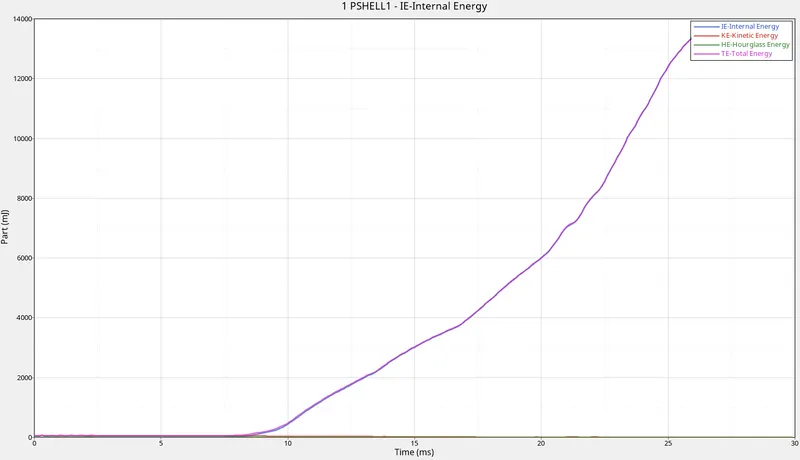
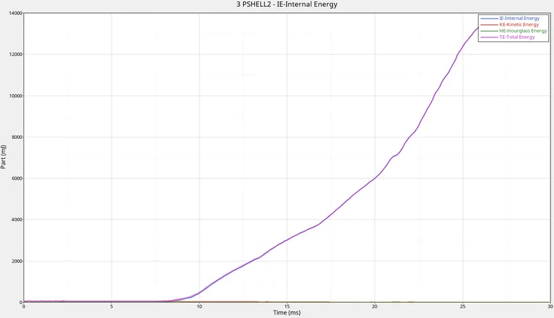
The graph for each component has also to be plotted which can be done by opening the solver deck entity. Under that open the TH file and under that create a part within it.In the pop-up menu, for the Entity ID select all four components and select the required variables needed to be plotted for each component and in the next Data:part, select the variables needed. Here the selected variables are IE, KE, HE and TE.
5. Run the simulation by going to the Radioss in the Analysis panel.Browse the location to which the simulation fiel has to be saved.
6. Check the export option have been turned to All, Run option as analysis and the run number as 1. In the option type-nt 4 to increase the speed of the simulation. Click on radioss.
7. At this time, the simulation starts to run and it may take a while longer,depending upon the model.
8. Change the hypermesh panel to Hyperview panel and browse the animation file from the previous saved simulation result. The Anim file will be in .h3d format.Click apply.
9. The animation file with the crash tube hitting the rigid wall will be devoloped.
10. Now split the window and open the Hypergraph 2D panel.
11.In the same simulation file check for T01 file and upload it in the Hypergraph.
12. Below that we can see the X Type and Y Type which is nothing but the X component and Y component.
On X axis, select the time as the constraint while in the Y axis, it is subdivided into three:
- Y Type
- Y Request
- Y Component13. In Y type, select Global variables.
In Y Request, select the energy constraints which we need.Here we took Kinetic energy,Internal energy,Hourglass enerfy,Contact energy and Total energy for consideration.
In Y Component, select the MAG OPTION. Click Apply.
14. Similarly, we plot another graph for Rigid wall forces which is the resultant normal and tangent force and the total resultant force as well as the graph to be plotted for each component or part seperetely.
15. Below are the graph plots which has been plotted:
(i) Global Variables:
This plot shows the variation in energies.
- Kinetic Energy: The kinetic energy of this model starts with a very high value from the initial stage (5.9E+07) and then gradually decreases.This is because at the initial stage of deformation happens with very high velocity and with applies mass of the body.But with time, when the force moves along the surface some energy will get disscipated along the path.So there will be slow decrement in the value of kinetic energy.
- Internal energy: It is the sum of kinetic energy and potential energy.when t=0 , the internal energy is zero as there where no deformation happening currently.But when the deformation starts, frictional force is devoloped along with some heat dessipation.With the intensity of deformation, the internal energy will be increased.
- Hourglass energy: Since the IShell properties of the model is IShell=0 by default and it is in underintegrated shell elements.In this under-integration only one point will be there for the elemental calculations where the force and displacements exist in each 4 nodes of the element.The summation of displacements and force sometimes provide zero strain and stress values and then the element fails to calculate the stiffness values.When it fails in such a way, it will result in some weird deformation and results in the formation of hourglass energy.Since the Ishell is given as QEPH 24 is applied in the property tab, the hourglass energy is reduced to zero with the physical stabilization happening in teh material level itself.
- Contact energy:This type of energy is formed when one element comes in contact with the other or neighbouring elements.The opposing force created by this element forms the contact energy.At the first stages of deformation, the contact energy goes constantly without any increase. But at the end of the simulation, with the high deformation or crushing happens, the contact energy will be devoloped and increases gradually. But in the above graph with all energy plotted in a single graph, the contact energy tends to form negligible.
- Total energy: The total energy of the system is the summation of all the energies happening with the component.The total energy is always conserved but the other energies like K.E is not conserved.Kinetic energy is very high at the initial stage due to the initial high velocity and the mass of the body applied to it.When the deformation starts, K.E is reduced and the internal energy is increased and the contact energy here is negligible.So the total energy will become constant.But with the formation of contact energy ,the total energy will be reduced to a value equal to the increase in contact energy.That is the reason why the total energy is getting slightly reduced from that value.
(ii)R-Wall
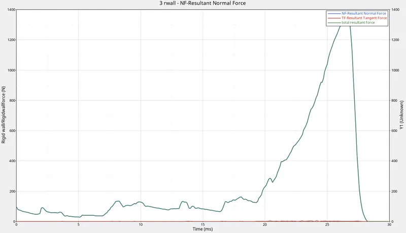
- Resultant normal force:The normal force is the force acting normal to the body.At the initial stage the resultant normal force starts with a low value. This is because at the initial stage the deformation happened is less and it strikes the wall with less velocity. After which the intensity of deformation reduces and when it reaches the half stage, then again there is a slight increase in the value as the deformation or the bending is higher at this stage and reaches a maximum value and drops back to zero.
- Resultant Tangent force: This is the force acting tangent to the body. The tangent force is similar to the frictional force. At start without any contact the resultant tangent force will be zero and minimally varies with time.
- Total Resultant Force: It is the sum of resultant normal and resultant tangent force.So when combined together it will plot a graph similar to the normal and tangent force.
(iii)Part/TH
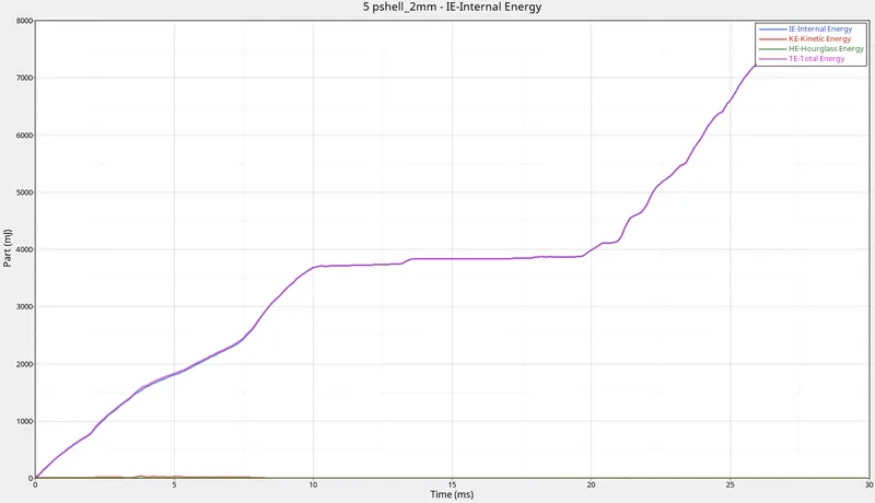
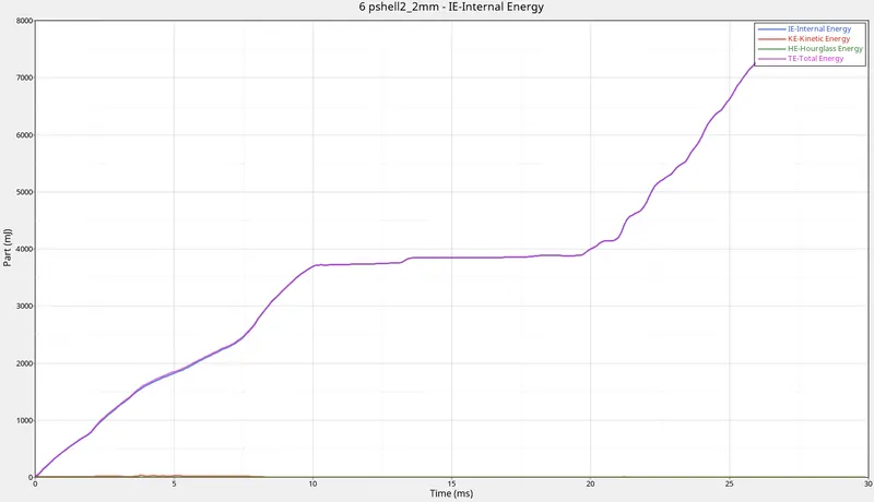
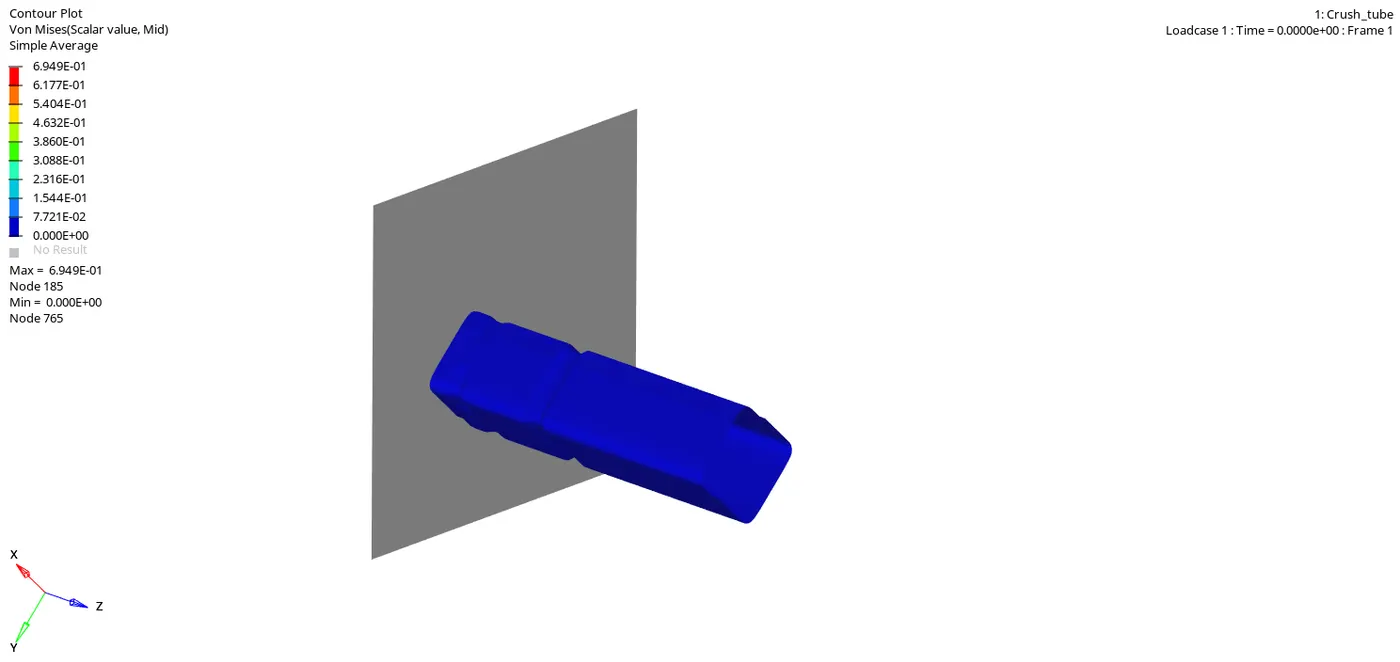
16. The animated simulation result(Von Mises) for case 2 is shown below:
CASE 3:
1. Open the Hypermesh in Radioss user profile.
2. Import the model in Solver deck and click import.
3. Create a TYPE 11 contact interface by right clicking the groups file in the model tab.In the pop-up menu bar, change the card image to TYPE 11 and change all the given values as same as that of type 7 in the previous card.
4. Now follow the steps similar to that of previous case till step 14.
5. Below are the graph plots which has been plotted:
(i) Global Variables:
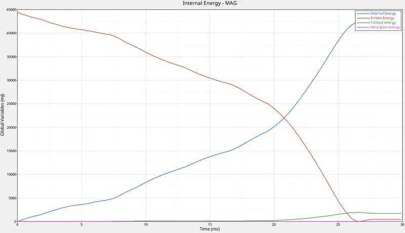
This plot shows the variation in energies.
- Kinetic Energy: The kinetic energy of this model starts with a very high value from the initial stage (5.9E+07) and then gradually decreases.This is because at the initial stage of deformation happens with very high velocity and with applies mass of the body.But with time, when the force moves along the surface some energy will get disscipated along the path.So there will be slow decrement in the value of kinetic energy.
- Internal energy: It is the sum of kinetic energy and potential energy.when t=0 , the internal energy is zero as there where no deformation happening currently.But when the deformation starts, frictional force is devoloped along with some heat dessipation.With the intensity of deformation, the internal energy will be increased.
- Hourglass energy: Since the IShell properties of the model is IShell=0 by default and it is in underintegrated shell elements.In this under-integration only one point will be there for the elemental calculations where the force and displacements exist in each 4 nodes of the element.The summation of displacements and force sometimes provide zero strain and stress values and then the element fails to calculate the stiffness values.When it fails in such a way, it will result in some weird deformation and results in the formation of hourglass energy.Since the Ishell is given as QEPH 24 is applied in the property tab, the hourglass energy is reduced to zero with the physical stabilization happening in teh material level itself.
- Contact energy:This type of energy is formed when one element comes in contact with the other or neighbouring elements.The opposing force created by this element forms the contact energy.At the first stages of deformation, the contact energy goes constantly without any increase. But at the end of the simulation, with the high deformation or crushing happens, the contact energy will be devoloped and increases gradually. But in the above graph with all energy plotted in a single graph, the contact energy tends to form negligible.
- Total energy: The total energy of the system is the summation of all the energies happening with the component.The total energy is always conserved but the other energies like K.E is not conserved.Kinetic energy is very high at the initial stage due to the initial high velocity and the mass of the body applied to it.When the deformation starts, K.E is reduced and the internal energy is increased and the contact energy here is negligible.So the total energy will become constant.But with the formation of contact energy ,the total energy will be reduced to a value equal to the increase in contact energy.That is the reason why the total energy is getting slightly reduced from that value.
(ii)R-Wall Graph
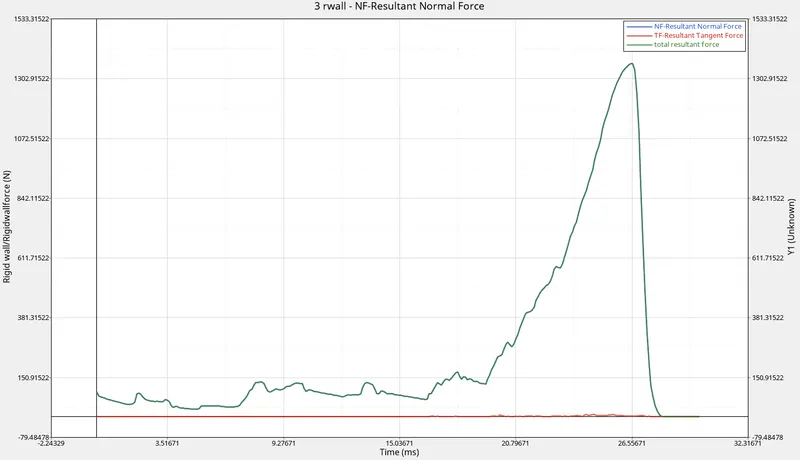
- Resultant normal force:The normal force is the force acting normal to the body.At the initial stage the resultant normal force starts with a low value. This is because at the initial stage the deformation happened is less and it strikes the wall with less velocity. After which the intensity of deformation reduces and when it reaches the half stage, then again there is a slight increase in the value as the deformation or the bending is higher at this stage and reaches a maximum value and drops back to zero.
- Resultant Tangent force: This is the force acting tangent to the body. The tangent force is similar to the frictional force. At start without any contact the resultant tangent force will be zero and minimally varies with time.
- Total Resultant Force: It is the sum of resultant normal and resultant tangent force.So when combined together it will plot a graph similar to the normal and tangent force.
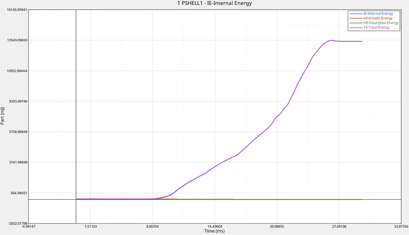
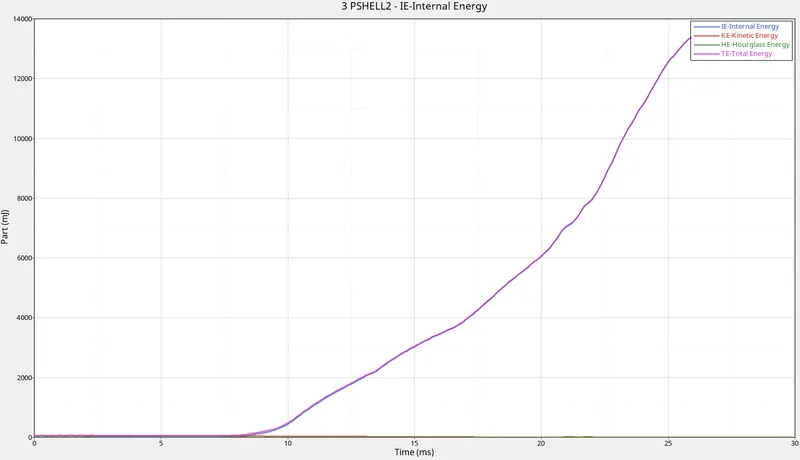
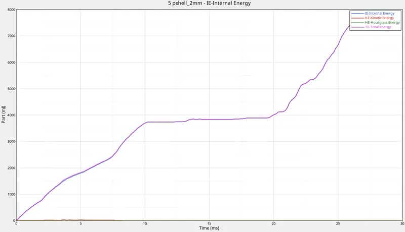
(iii)Part/TH
 \
\
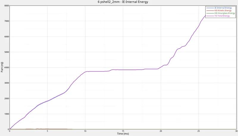
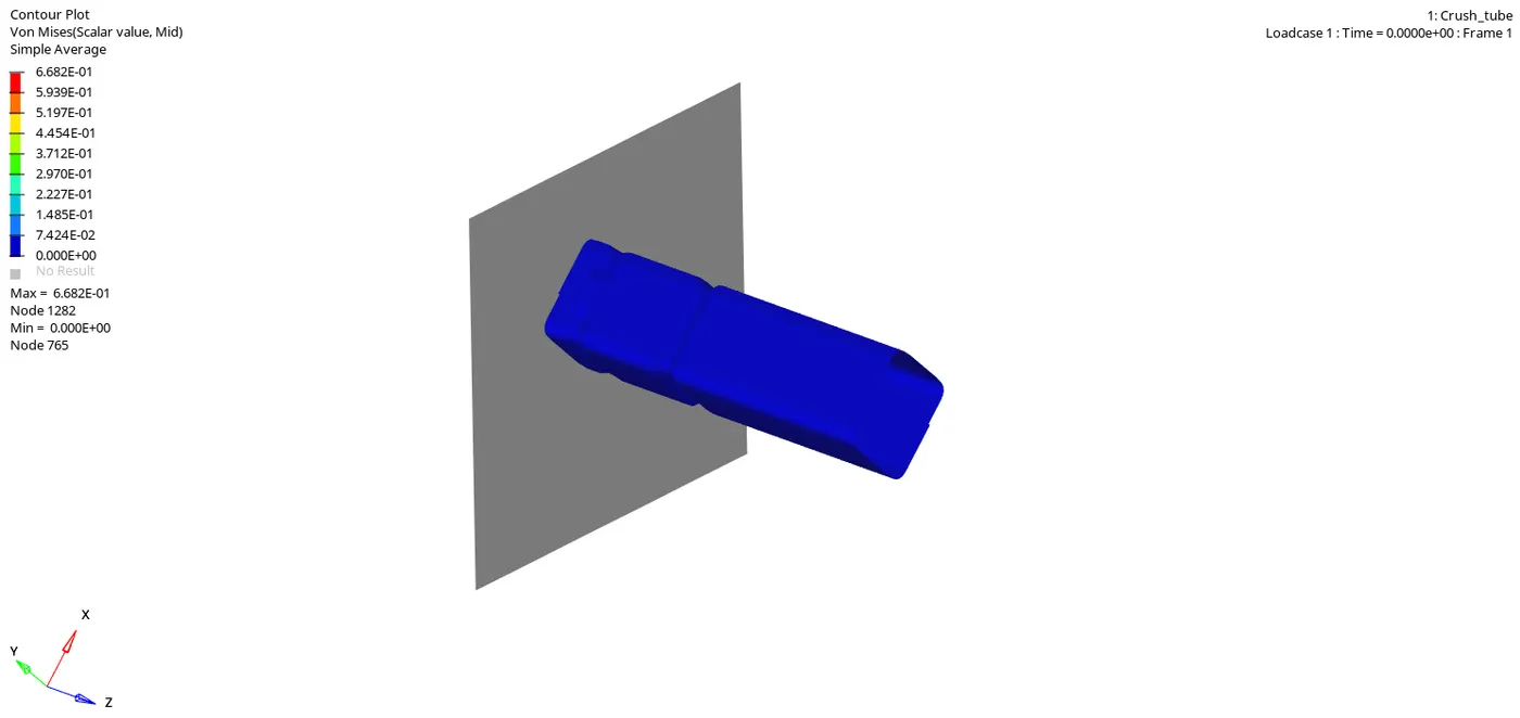
6. The animated simulation result(Von Mises) for case 3 is shown below:
CASE 4:
1. In this case, the notch in the part has to be removed and keep it as a flat surface. Also the boundary conditions has to be removed ie. all DOF has to be unchecked.
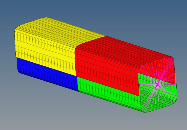
The notches in the surface can be removed using the Align option which is available in the node edit tool in the geometry panel.
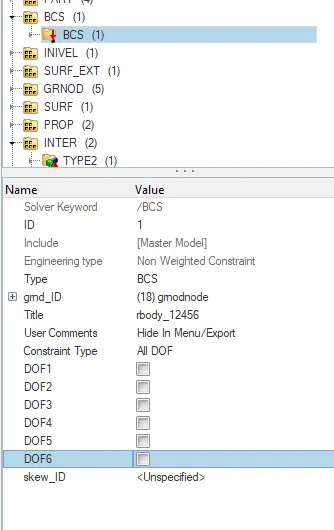
2. The DOF can be unchecked in the BCS(boundary condition) file in the solver tab.
3.Run the simulation as per case 2 till graph plotting.
4. Below are the graph plots which has been plotted:
(i) Global Variables:
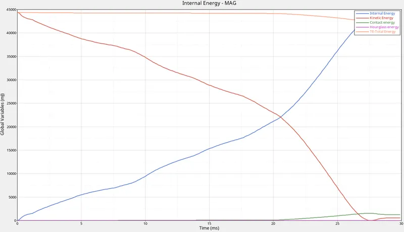
This plot shows the variation in energies.
- Kinetic Energy: The kinetic energy of this model starts with a very high value from the initial stage (5.9E+07) and then gradually decreases.This is because at the initial stage of deformation happens with very high velocity and with applies mass of the body.But with time, when the force moves along the surface some energy will get disscipated along the path.So there will be slow decrement in the value of kinetic energy.
- Internal energy: It is the sum of kinetic energy and potential energy.when t=0 , the internal energy is zero as there where no deformation happening currently.But when the deformation starts, frictional force is devoloped along with some heat dessipation.With the intensity of deformation, the internal energy will be increased.
- Hourglass energy: Since the IShell properties of the model is IShell=0 by default and it is in underintegrated shell elements.In this under-integration only one point will be there for the elemental calculations where the force and displacements exist in each 4 nodes of the element.The summation of displacements and force sometimes provide zero strain and stress values and then the element fails to calculate the stiffness values.When it fails in such a way, it will result in some weird deformation and results in the formation of hourglass energy.Since the Ishell is given as QEPH 24 is applied in the property tab, the hourglass energy is reduced to zero with the physical stabilization happening in teh material level itself.
- Contact energy:This type of energy is formed when one element comes in contact with the other or neighbouring elements.The opposing force created by this element forms the contact energy.At the first stages of deformation, the contact energy goes constantly without any increase. But at the end of the simulation, with the high deformation or crushing happens, the contact energy will be devoloped and increases gradually. But in the above graph with all energy plotted in a single graph, the contact energy tends to form negligible.
- Total energy: The total energy of the system is the summation of all the energies happening with the component.The total energy is always conserved but the other energies like K.E is not conserved.Kinetic energy is very high at the initial stage due to the initial high velocity and the mass of the body applied to it.When the deformation starts, K.E is reduced and the internal energy is increased and the contact energy here is negligible.So the total energy will become constant.But with the formation of contact energy ,the total energy will be reduced to a value equal to the increase in contact energy.That is the reason why the total energy is getting slightly reduced from that value.
(ii) R Wall Graph:
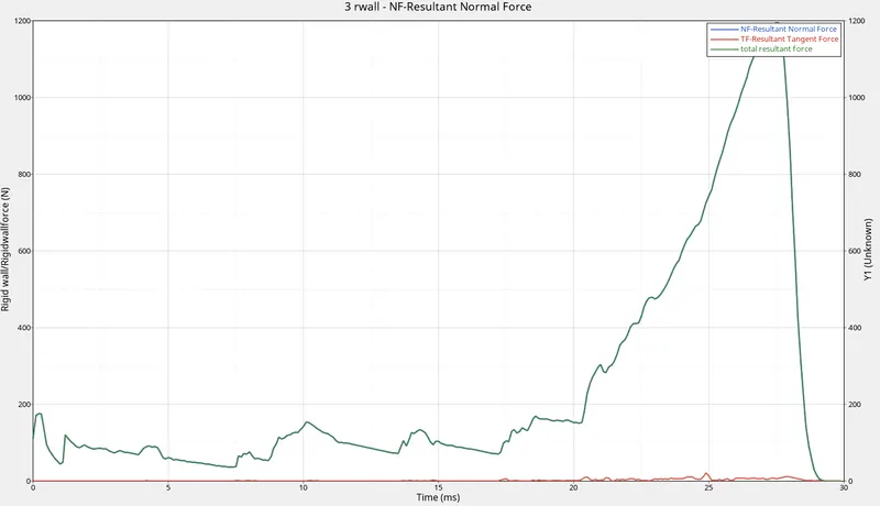
- Resultant normal force:The normal force is the force acting normal to the body.At the initial stage the resultant normal force starts with a low value. This is because at the initial stage the deformation happened is less and it strikes the wall with less velocity. After which the intensity of deformation reduces and when it reaches the half stage, then again there is a slight increase in the value as the deformation or the bending is higher at this stage and reaches a maximum value and drops back to zero.
- Resultant Tangent force: This is the force acting tangent to the body. The tangent force is similar to the frictional force. At start without any contact the resultant tangent force will be zero and minimally varies with time.
- Total Resultant Force: It is the sum of resultant normal and resultant tangent force.So when combined together it will plot a graph similar to the normal and tangent force.
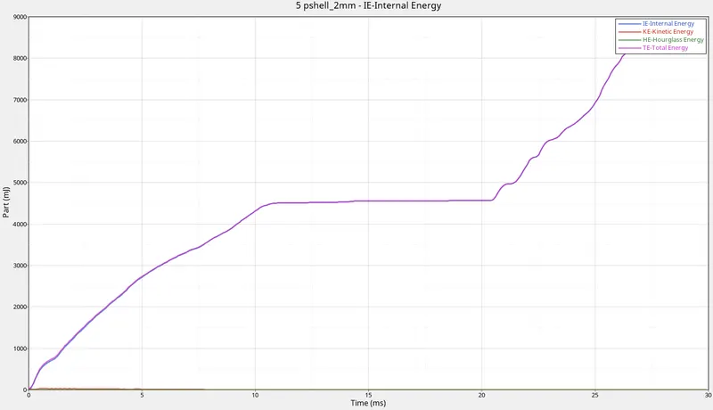
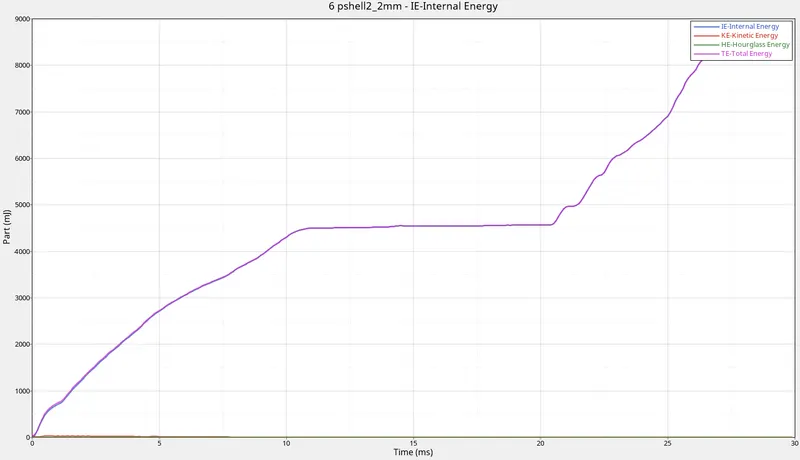
Part/TH:
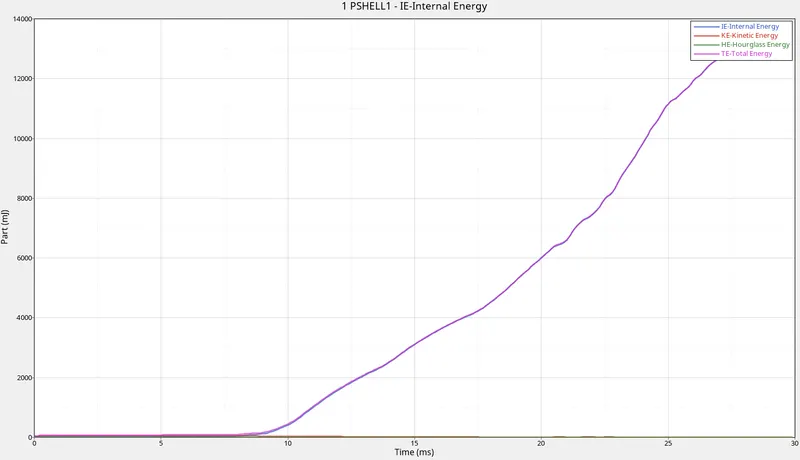
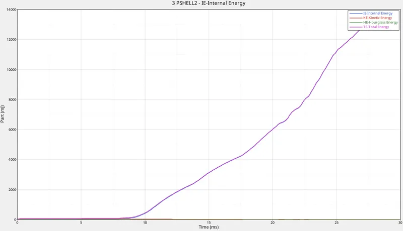
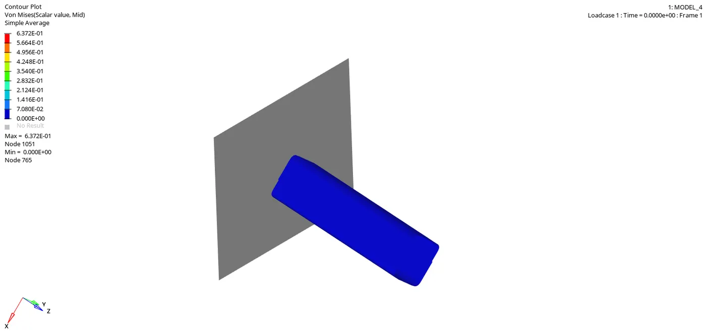
5. The animated simulation result(Von Mises) for case 4 is shown below:
CASE 5:
1. In this simulation, create a notch at the middle of the entire component.
2. This can be done using the translate option and giving an offset value of 3.4(approx.)
3.Now run the simulation similarly as in the case 2 till plotting the graph.
4. Below are the graph plots which has been plotted:
(i) Global Variables:
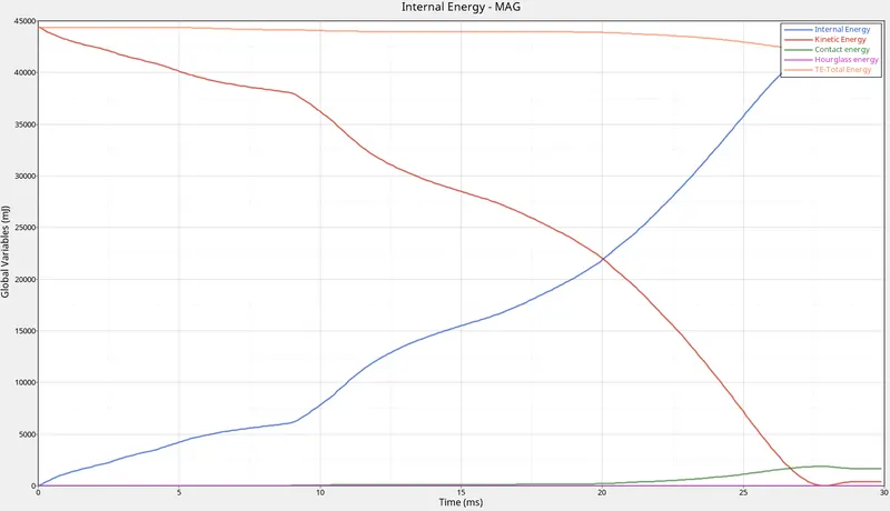
This plot shows the variation in energies.
- Kinetic Energy: The kinetic energy of this model starts with a very high value from the initial stage (5.9E+07) and then gradually decreases.This is because at the initial stage of deformation happens with very high velocity and with applies mass of the body.But with time, when the force moves along the surface some energy will get disscipated along the path.So there will be slow decrement in the value of kinetic energy.
- Internal energy: It is the sum of kinetic energy and potential energy.when t=0 , the internal energy is zero as there where no deformation happening currently.But when the deformation starts, frictional force is devoloped along with some heat dessipation.With the intensity of deformation, the internal energy will be increased.
- Hourglass energy: Since the IShell properties of the model is IShell=0 by default and it is in underintegrated shell elements.In this under-integration only one point will be there for the elemental calculations where the force and displacements exist in each 4 nodes of the element.The summation of displacements and force sometimes provide zero strain and stress values and then the element fails to calculate the stiffness values.When it fails in such a way, it will result in some weird deformation and results in the formation of hourglass energy.Since the Ishell is given as QEPH 24 is applied in the property tab, the hourglass energy is reduced to zero with the physical stabilization happening in teh material level itself.
- Contact energy:This type of energy is formed when one element comes in contact with the other or neighbouring elements.The opposing force created by this element forms the contact energy.At the first stages of deformation, the contact energy goes constantly without any increase. But at the end of the simulation, with the high deformation or crushing happens, the contact energy will be devoloped and increases gradually. But in the above graph with all energy plotted in a single graph, the contact energy tends to form negligible.
- Total energy: The total energy of the system is the summation of all the energies happening with the component.The total energy is always conserved but the other energies like K.E is not conserved.Kinetic energy is very high at the initial stage due to the initial high velocity and the mass of the body applied to it.When the deformation starts, K.E is reduced and the internal energy is increased and the contact energy here is negligible.So the total energy will become constant.But with the formation of contact energy ,the total energy will be reduced to a value equal to the increase in contact energy.That is the reason why the total energy is getting slightly reduced from that value.
(ii)R Wall Graph:
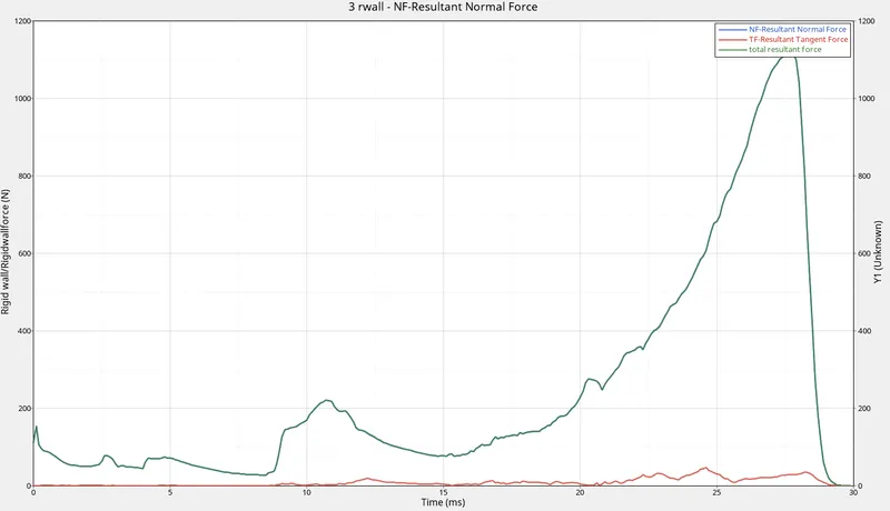
- Resultant normal force:The normal force is the force acting normal to the body.At the initial stage the resultant normal force starts with a low value. This is because at the initial stage the deformation happened is less and it strikes the wall with less velocity. After which the intensity of deformation reduces and when it reaches the half stage, then again there is a slight increase in the value as the deformation or the bending is higher at this stage and reaches a maximum value and drops back to zero.
- Resultant Tangent force: This is the force acting tangent to the body. The tangent force is similar to the frictional force. At start without any contact the resultant tangent force will be zero and minimally varies with time.
- Total Resultant Force: It is the sum of resultant normal and resultant tangent force.So when combined together it will plot a graph similar to the normal and tangent force.
(iii) Part/TH:
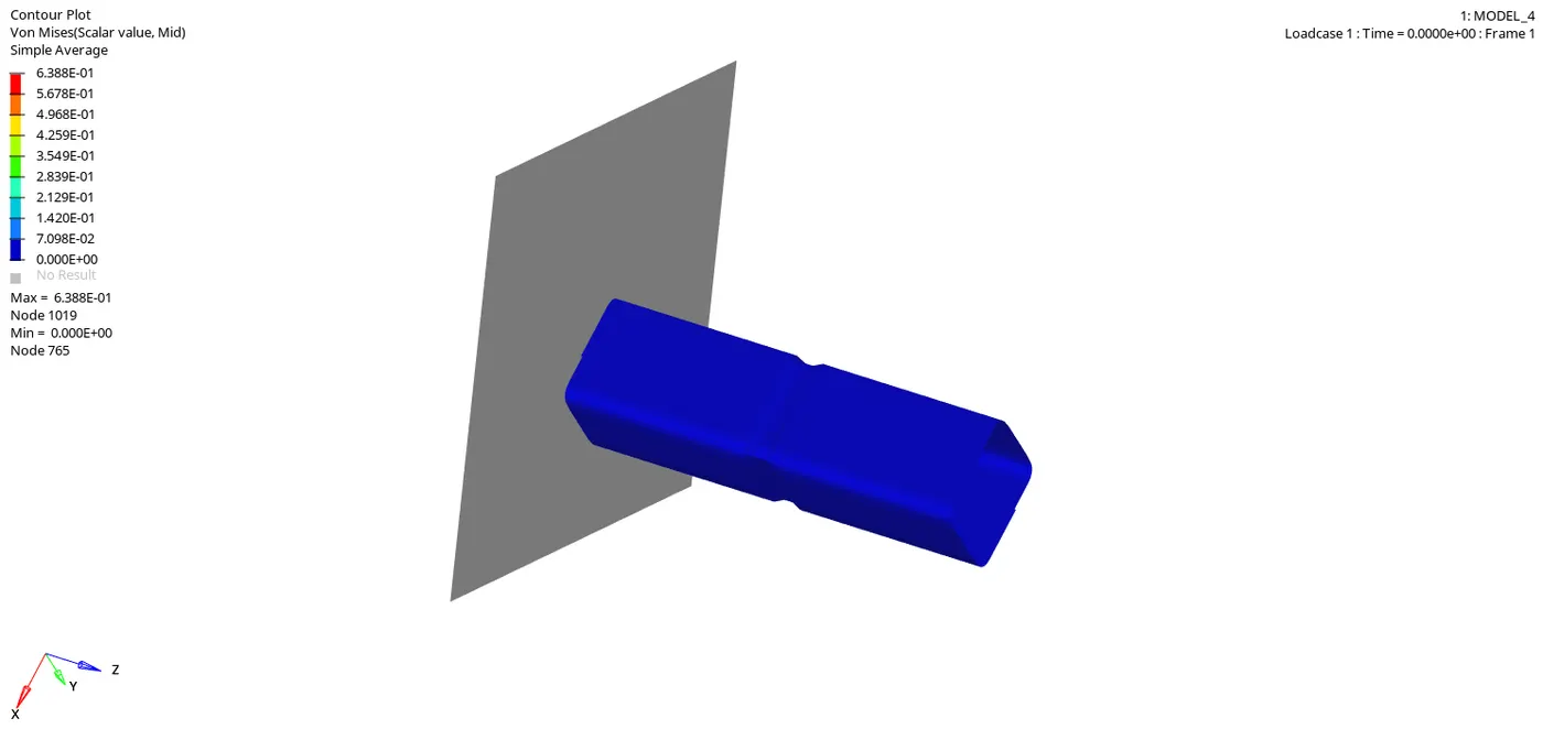
5. The animated simulation result(Von Mises) for case 5 is shown below:
CASE 6:
1. In this simulation, create a new notch with nodes only from the opposing faces.
2. This can be done using the translate tool in the node edit panel.
3. Run the simulation as per the previous cases till graph plotting.
4.Below are the graph plots which has been ploted:
(i) Global Variables:
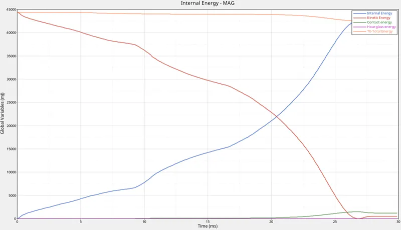
This plot shows the variation in energies.
- Kinetic Energy: The kinetic energy of this model starts with a very high value from the initial stage (5.9E+07) and then gradually decreases.This is because at the initial stage of deformation happens with very high velocity and with applies mass of the body.But with time, when the force moves along the surface some energy will get disscipated along the path.So there will be slow decrement in the value of kinetic energy.
- Internal energy: It is the sum of kinetic energy and potential energy.when t=0 , the internal energy is zero as there where no deformation happening currently.But when the deformation starts, frictional force is devoloped along with some heat dessipation.With the intensity of deformation, the internal energy will be increased.
- Hourglass energy: Since the IShell properties of the model is IShell=0 by default and it is in underintegrated shell elements.In this under-integration only one point will be there for the elemental calculations where the force and displacements exist in each 4 nodes of the element.The summation of displacements and force sometimes provide zero strain and stress values and then the element fails to calculate the stiffness values.When it fails in such a way, it will result in some weird deformation and results in the formation of hourglass energy.Since the Ishell is given as QEPH 24 is applied in the property tab, the hourglass energy is reduced to zero with the physical stabilization happening in teh material level itself.
- Contact energy:This type of energy is formed when one element comes in contact with the other or neighbouring elements.The opposing force created by this element forms the contact energy.At the first stages of deformation, the contact energy goes constantly without any increase. But at the end of the simulation, with the high deformation or crushing happens, the contact energy will be devoloped and increases gradually. But in the above graph with all energy plotted in a single graph, the contact energy tends to form negligible.
- Total energy: The total energy of the system is the summation of all the energies happening with the component.The total energy is always conserved but the other energies like K.E is not conserved.Kinetic energy is very high at the initial stage due to the initial high velocity and the mass of the body applied to it.When the deformation starts, K.E is reduced and the internal energy is increased and the contact energy here is negligible.So the total energy will become constant.But with the formation of contact energy ,the total energy will be reduced to a value equal to the increase in contact energy.That is the reason why the total energy is getting slightly reduced from that value.
(ii) R wall graph:
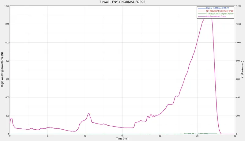
- Resultant normal force:The normal force is the force acting normal to the body.At the initial stage the resultant normal force starts with a low value. This is because at the initial stage the deformation happened is less and it strikes the wall with less velocity. After which the intensity of deformation reduces and when it reaches the half stage, then again there is a slight increase in the value as the deformation or the bending is higher at this stage and reaches a maximum value and drops back to zero.
- Resultant Tangent force: This is the force acting tangent to the body. The tangent force is similar to the frictional force. At start without any contact the resultant tangent force will be zero and minimally varies with time.
- Total Resultant Force: It is the sum of resultant normal and resultant tangent force.So when combined together it will plot a graph similar to the normal and tangent force.
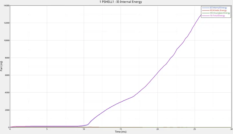
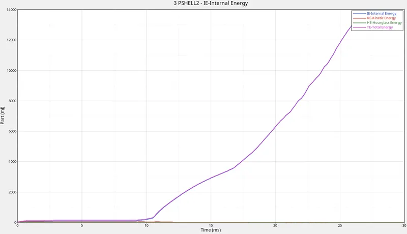
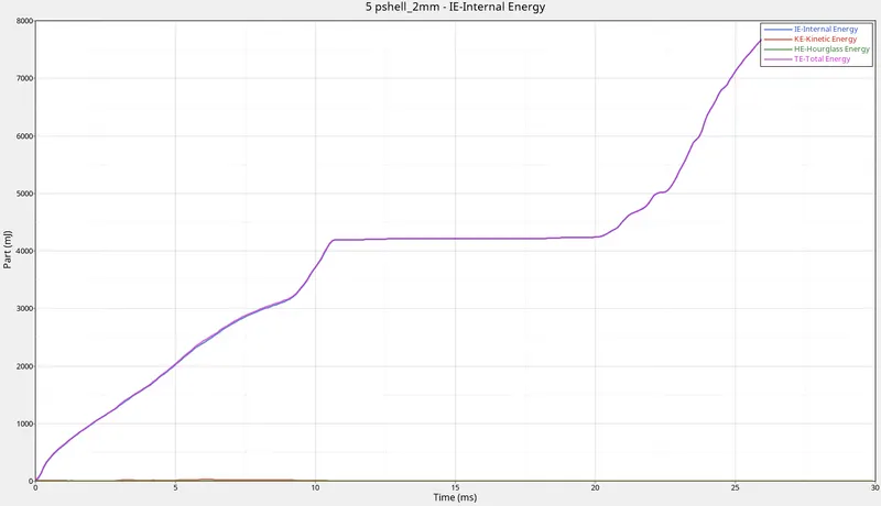
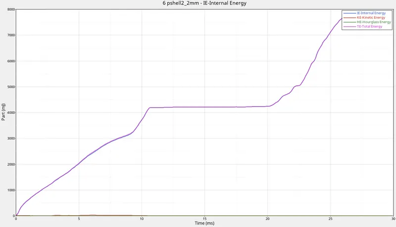
Part/ TH graph:
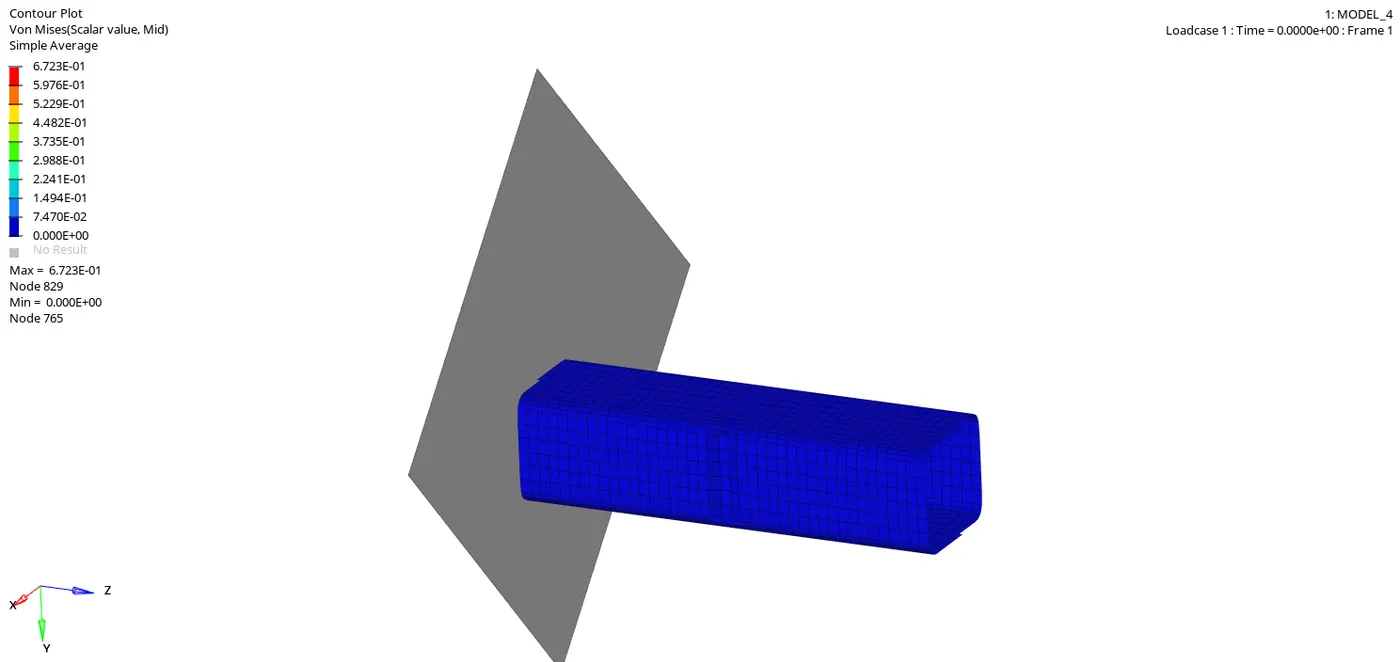
5. The animated simulation result(Von Mises) for case 6 is shown below:
AFFECT OF NOTCHES IN THE RESULT:
The notches in the model affect the contact energy.With teh increment of notches, it absorbs energy and less deformations have been formed and thus contact energy is reduced.
CONCLUSION:
All the cases have been simulated with the given criterias and gaph has been plotted with global variables like IE,KE,TE and HE and also the RWall forces have also been plotted and compared.