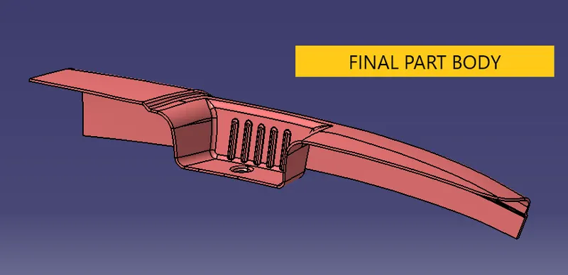
Door Arm Rest Week 8 Challenge
AIM:
To design the door arm rest of the side door with the part thickness of 2.5mm from the aesthetic class A surface.
PROCEDURE:
First create the tooling axis for the part which will clear the entire part with a draft angle of a minimum of 3 degree.
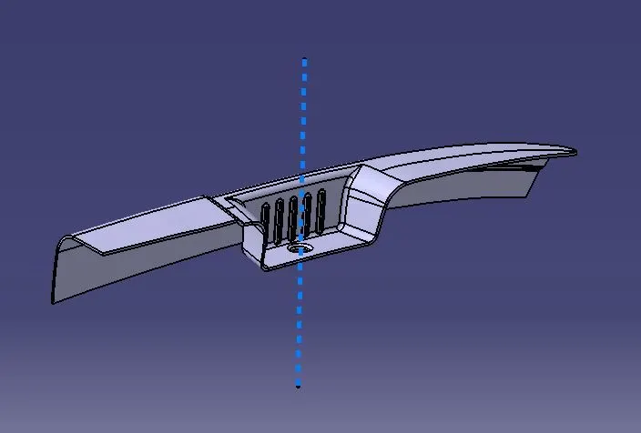
Inorder to create a tooling axis, first create a point in the bottom hole and an axis system at the same point.
Then using the intersection tool, create an intersection curve in the XZ and YZ plane. Then create two lines along that curve which you think the curve is more than three degree angle.
With the two lines created, create a biscecting line which will give the tooling axis in one plane. Similarly with the same procedures, create the tooling axis in YZ plane.
With the feature draft analysis check whether the tooling axis created is clearing all with the specified angle.
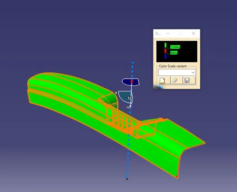
After tooling axis is created, go for the generative shape design, starting with extracting each parts without considering any fillets.
After extracting each part, untrim the part and extrapolate the part if needed whether to be in no propagation or in point continuity.
In the door arm part only the double fillet area will be harder which can be executed using extracting the tangent line connecting the two fillets with the Sweep function with the reference surface. By creating a profile and a guide curve, one could execute to generate the fillets.
After extrapolation, the parts has to be offseted to a distance of 2.5mm with the proper direction for offseting. This can be cross checked by unhiding the class A surface.
After which trim the surfaces created with respect to the class A surface design.
After the class B surface is created, provide proper fillets to all the edges required which is, if the fillets given has to the inner radius then the fillet value will be outer fillet radius-part thickness and for the outer fillet, the fillet value is inner fillet radius radius+ part thickness.
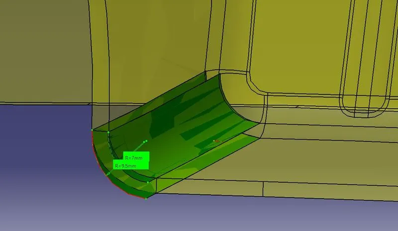
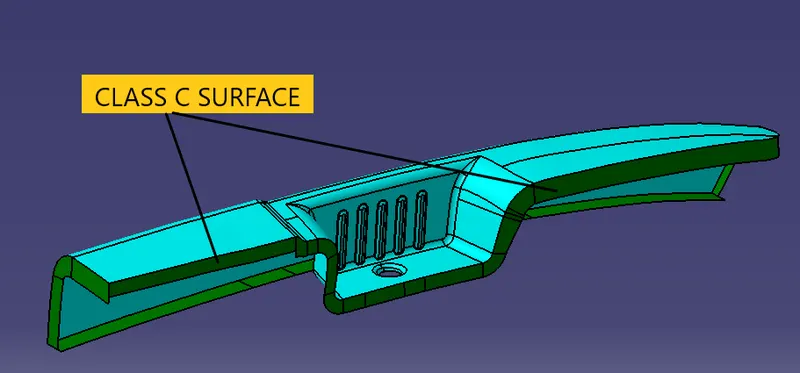
Now the class C surface has to be created using the sweep function with the tooling axis as the pulling direction along the boundary of the A surface
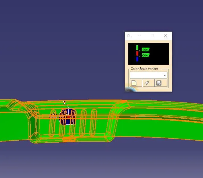
A side tooling axis has also to be created to clear the draft in the areas where the main tooling has not cleared. The draft analysis of the side tooling which clears the other parts are given below:
After which trim the former with class B and a proper part will be formed, but the inside of it will be hollow.
Inorder to make it a solid part, change the profile to part design where using the close surface option, we can make the part into a solid.