Week 12 - Project-1
AIM:
To extract the midsurface and generate the mesh in the given plastic model of a side door panel with the given quality criterias and a better mesh flow with capturing all necessary features and assign thickness to each component having varying thickness.
OBJECTIVE:
- Cleanup the geometrical errors and remove all deformations in the model.
- Extract the mid-surface of the model.
- Check for all features where minimum length probably fails, and make changes accordingly.
- Mesh the component with the given element size and remove all the qulaity errors with proper feature capturing.
- Assign thickness for all features with varying thickness.
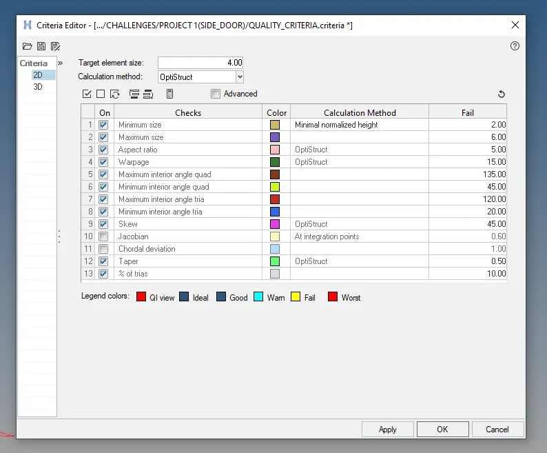
QUALITY CRITERIA:
Target element length: 4mm
| S.N | Quality Criteria | Value |
| 1 | Aspect Ratio | 5 |
| 2 | Skewness | 45 |
| 3 | Warping | 15 |
| 4 | Taper | 0.5 |
| 5 | Min. Length | 2mm |
| 6 | Max. Length | 6mm |
| 7 | Min angle Quad | 45 |
| 8 | Max angle Quad | 135 |
| 9 | Min angle Tria | 20 |
| 10 | Max angle Tria | 120 |
| 11 | Tria % | 10 |
PROCEDURE:
- Import the model which is currently in .hm format which can be opened either by double clicking on the file or using File-> Import-> Model option, where select the file from the respective file location.
- Analyse and check the model carefully, as it is a plastic component, thereby it may have varying thickness and many deformations which has to be rectified.
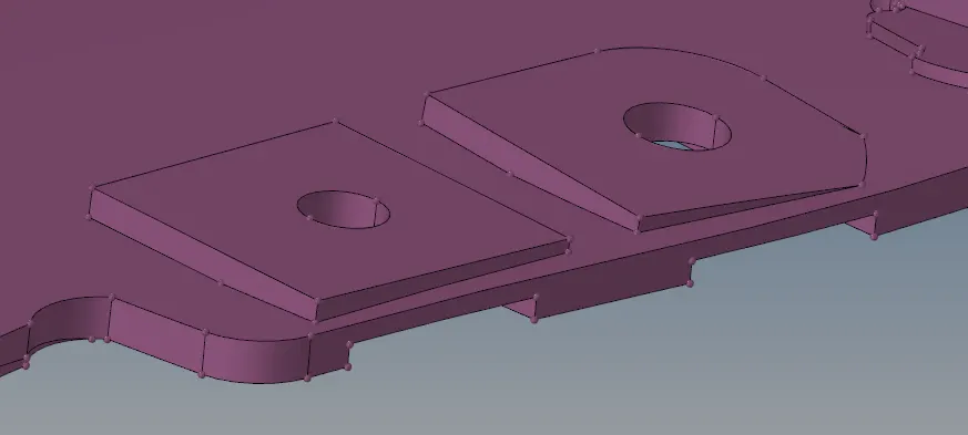
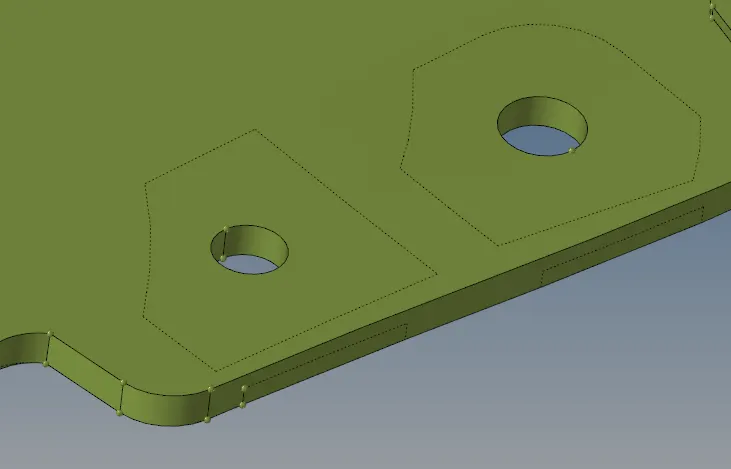
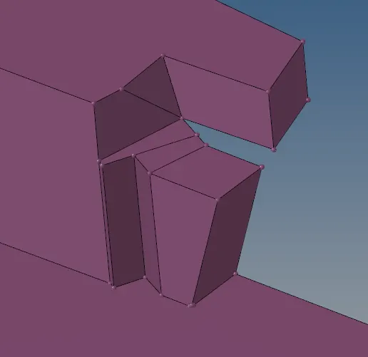
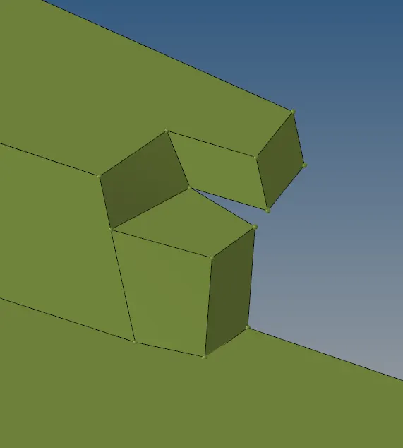
- Some of the major deformations in the model are given below with pre and post worked in the same.
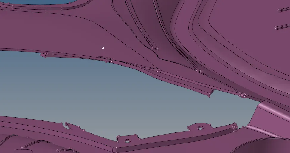
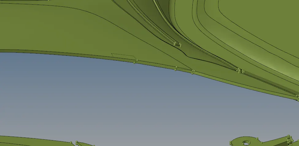
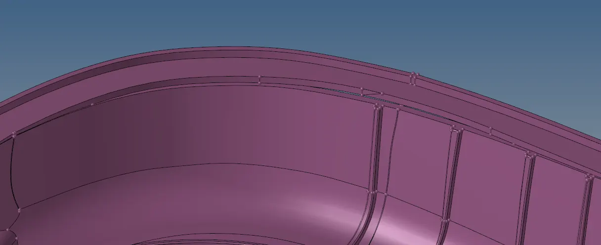
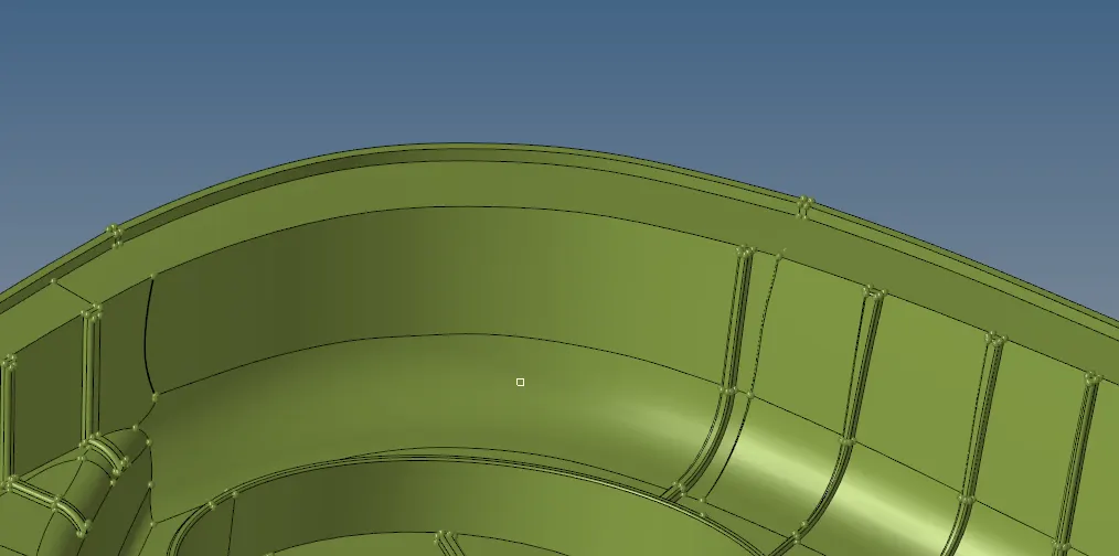
- Likewise, check all parts in the model by going through each area and remove all the deformations, gaps, free edges as well as T-connections and make a perfect parent geometry out of it.
- Other geometry cleanup includes removing unwanted or extra features which might fail for the minimum length which can be removed or altered in the parent itself, so that an exact replica can be obtained.
- After the completion of geometry cleanup, start the process of extracting mid-surface out from the component which will take the most time out of all these stages till completion.
- Since it is a plastic component with varying thickness, the mid cannot be extracted in a single shot, rather after extracing the base surface, attach each and every ribs and features on to the base surface, thereby an exact replica of the parent geometry can be obtained.To start with, extract the outer base surface from the parent. Upon close examination. the overall thickness of the base surface can be obtained as 2.8mm thick.
- For plastic parts the thickness can be calculated with the project option in tools panel. Goto Tools-> Project (Shift+F7)-> Surface-> Nodes-> selct the node on one side of any surface where you have to find the thickness by left clicking the mouse and dragging it along the surface, after which a temporary node will be created on the surface, which youi have to duplicate it twice and in the To Surface option, select the opposite surface where the node needs to get projected ->and click Project. Two nodes will be created in the exact opposite sides where you can calculate the distance using Geometry-> Distance (F4) ->Nodes-> Select the two nodes and the distance will be shown.


- After checking the thickenss randomly in each parts, we conclude that the base surface is of uniform thickness and the midsuraface can be extracted with the offset tool in the surface edit option in the geometry panel.
- Select the offset option, change it to continous offset from disjoint and select the surface and click on by face so that the entire base surface get selected and offset it with the reqired dimensions and proper vector directions.

(Note: The colour normals include Red as well as Blue where we have to select the blue colour normal)
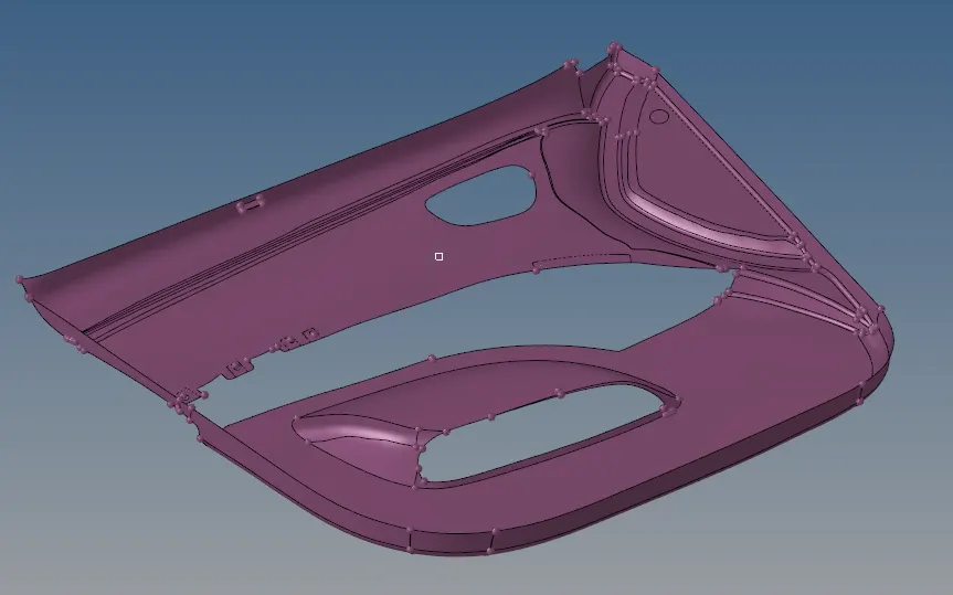
- Once the mid is extracted check on all parts if its formed exactly as the parent without any deformations, so that you can move out to the next step.
- Next step is to attach the outer flange connecting the boundaries of the base surface. Just like the same project and offset tool, measure the distance and take an average of the measured value and offset it.
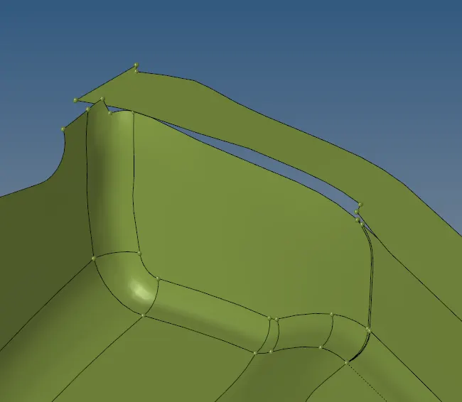
- Inorder to connect these two surfaces together, the best option is using Geometry->surfaces->Drag along vector tool, where a surface can be draged along the specified vector direction. After which two surfaces got extended one step remaining is to intersect or connect the surfaces.Inorder for that the tool used will be Trim with surfaces option in surface edit toolbar. In Trim with surfaces use the Self intersecting surfaces, select all the surfaces which needs to be intersected and trim. It automatically finds the surfaces with intersections and trim accordingly.

- If this tool doesn't work, go for midline tool in line toolbar where you can create a mid line on the surface and project that line to the destination surface and a surface can be created over there with the ruled option in the surface panel.
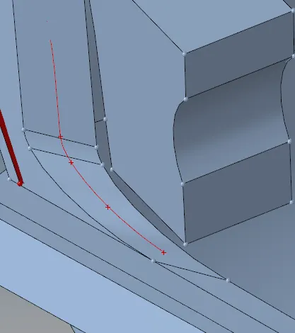
- After completing with the surfaces, go for each ribs which has to be manually offseted and defeatured.Since the ribs are of uneven shapes and has to be defeatured inorder to obtain a better mid, defeature it by removing all fillets from it.This can be done using Geometry-> Defeature->Surface fillets->In find fillets in selcted, select the surfaces or fillets which needs to be removed and assign values for minimum radius as 0.1 and maximum radius as 20 and click on Find.


- Now a secondary panel will be opened where we can add the selection of the surfaces and select the edges of the surfaces which we have selected and click Remove.
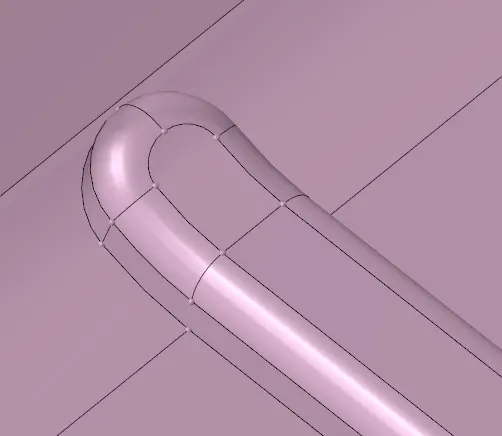
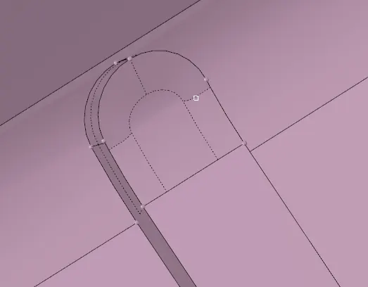
- If this doesnt work, we have to do the defeaturing manually using the drag along vector tool as explained earlier.
- Each fillets have to be manually offseted and are many ways to do the same.Some of the methods are:
Using mid-line tool, where create the midline from the rib and project it to the base surface create a surface in between the lines as shown below:
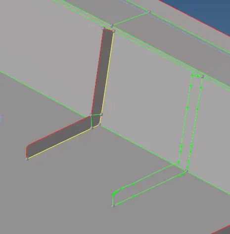
Using the Final edit tool in the midsurface tool in geometry panel where select the to sides of a part and a midplane will be formed in between the two sides selected.

- After all the ribs are created with the above given tools, most of the ribs has to be extended to the base surfaces upon analysing closely.This is done using Geometry panel-> surface edit-> Extend->Change the Max extension to Extend over edges and on the destination, change it to surfs:to target from cross extension.In the option of lines to extend over select the bottom edge of the ribs we we need to be extended and the destination as base surface just below the rib and click on Extend.

{Note:When extended, a T-connection line will be formed in the intersection of the two}
- Likewise, all ribs has to be attached in the similar way as in the parent geometry.
- When the midsurfacing is completed by following all the above steps, proceed with meshing. Before start to mesh, check for all fillets and surfaces where the minimum length fails and rectify or defeaure all those areas and toggle lines wherever necessary.
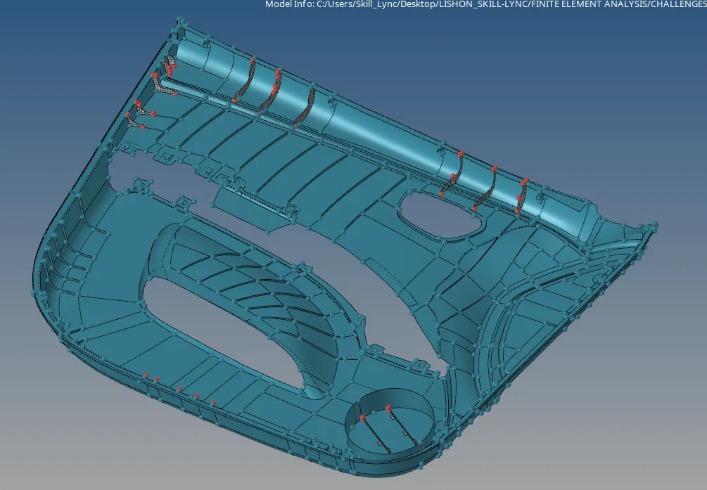
- The extracted midsurface with all the features captured is shown below:
- Ensure that the current compound selected is the midsurface and in the Criteria file settings in the preference tool change all the quality values as per given in the question with target length as 4mm.
- Analyse the model to confirm where to start the model ,so that a better mesh flow and tria management can be devoloped at the end of the meshing.The suitable part to start the meshing is from the speaker holder part, which is the most complex part to get the meshing done.

- Before starting, change the Geometry colour mode to By Topo and the Element colour mode as By Element Quality so that all the failed elements can be visible while meshing.Also change the shaded geometry to wireframe mode, so that component can be easily meshed without difficulties or glitches.
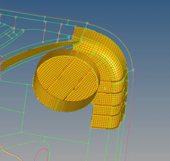
- The meshing is done with the Automesh tool in the 2D Panel, where select the surface to be meshed.In the size and Bias,
Element size = 4mm
Mesh type = Mixed
Tick on the Align and Size in the Flow option.Click the mesh button and that purticular area will get meshed. To do a remesh instead of surfs select the elements and window select a small regions of elements where you have to remesh and click mesh.

- The trias formed in the generated mesh can be removed using the Quality Index tool in the 2D panel. A lot of Tria management tools are available in this toolbar which includes:
Place node: this tool allows to move thenodes along any direction parellel to the surface.
Smooth: This allows to align the mesh and helps to remove the quality errors formed.
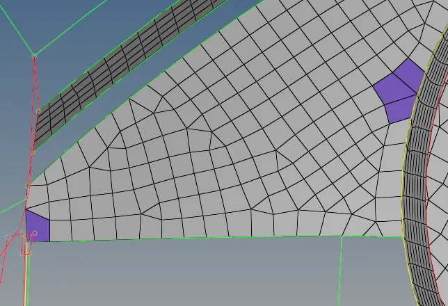
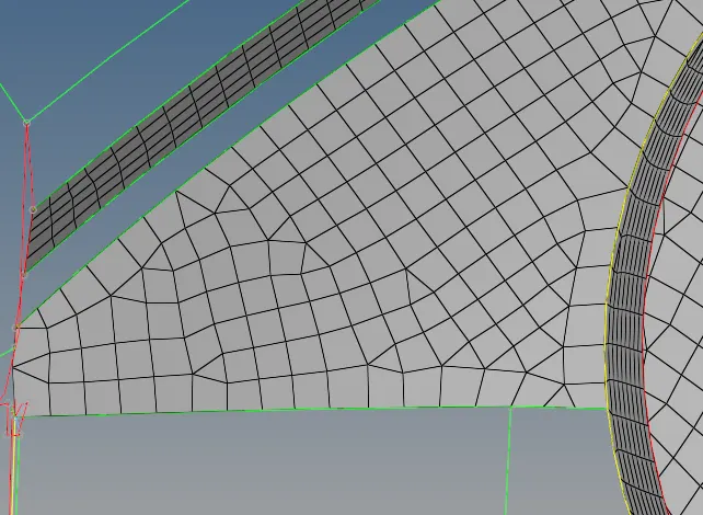
Swap edge: This helps to swap the edges of the elements to the adjacent elements so that trias can be moved along the surface.
Split/Collapse edges: This helps to split the trias, thereby helps to move the tria forward.
Drag Tria Element: This is one of the most important and frequently used tool in QI. This moves the tria or can be draged along anywhere(either to split up or paste the trias).After this tool is carried out note to smooth that particular region to get a better mesh flow.
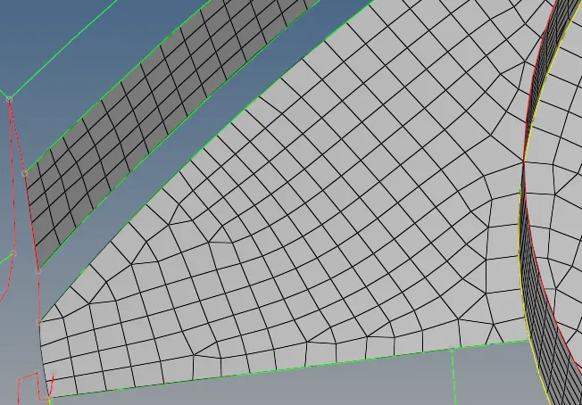
Element optimize: By clicking on the neighbouring areas of the failed elements, it helps to remove most of the failed elements irrespective of the mesh flow.
- With each parts meshed, the mesh flow must be continous with the other.This can be achieved using the Smooth option in the 2D panel.This allows to smooth or align the mesh flow irrespective of the quality parameters.

Inorder to do a smooth operation goto 2D-> Smooth(shift+F12)->select the element by geom option.another secondary panel will be opened and click which all surfaces to be selected and give the iteration as 30 so that with a single click, the smoothing will be done for 30 times.
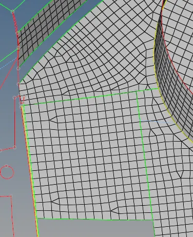
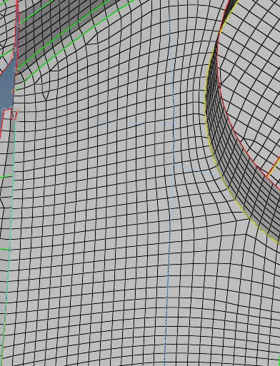
The above figure shows the mesh flow before and after using the QI tool.
- The meshing has to done or completed in a flow rather than doing a random meshing in different areas.The generated mesh for the entire component is shown below:
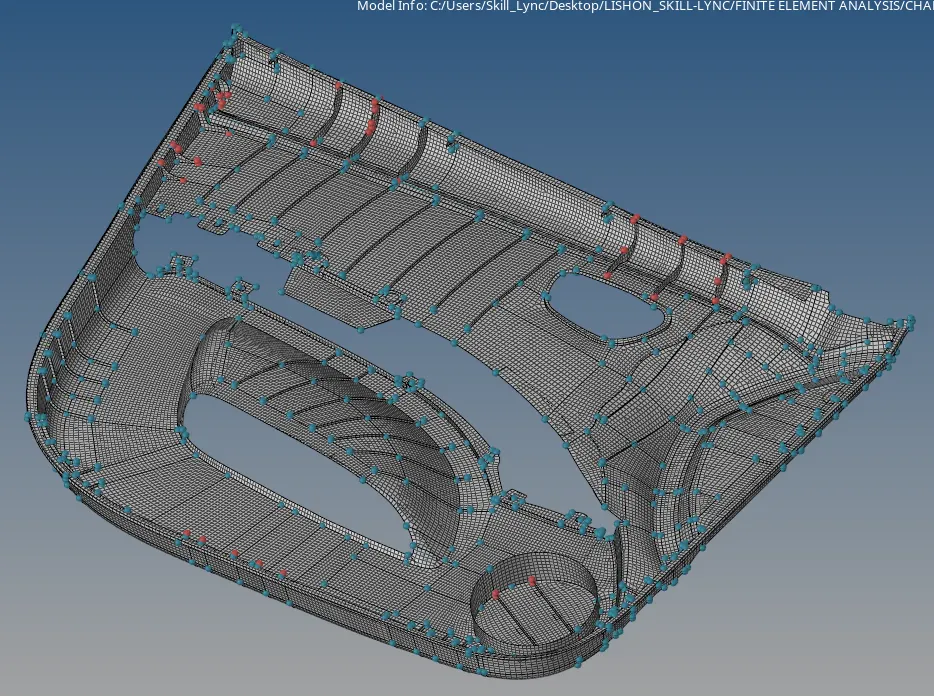
- The meshing is done as per the given quality parameters with tria percentage of 1.1
- After the generation of mesh and post which the free edges has to be checked in the geometry using Edge option in the Tool panel.

- In this tool instead of components, select the element as the type and window select the entire geometry and click free edge option.Ensure that the element colour code has been changed to By Comp, so that free edge lines are visible clearly.If no free edges are formed in between the surfaces , then your model is free from free edges.
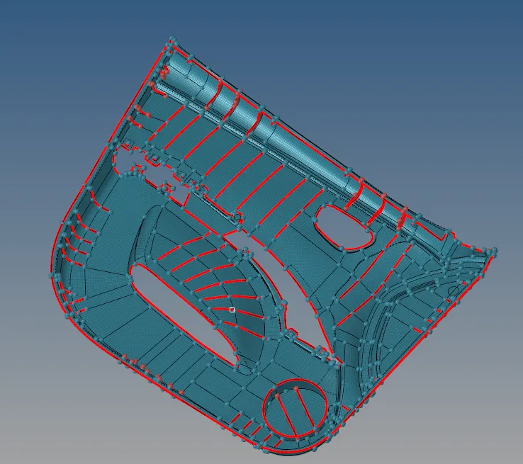
- If there is any free edges fix it either using the equivalence tool in the edge option itself. When preview equiv is given it will show areas where to fix and click on Equivalence to fix it.Another way of doing it manually is by Replace option (F3) where you can replace it to form a single one.

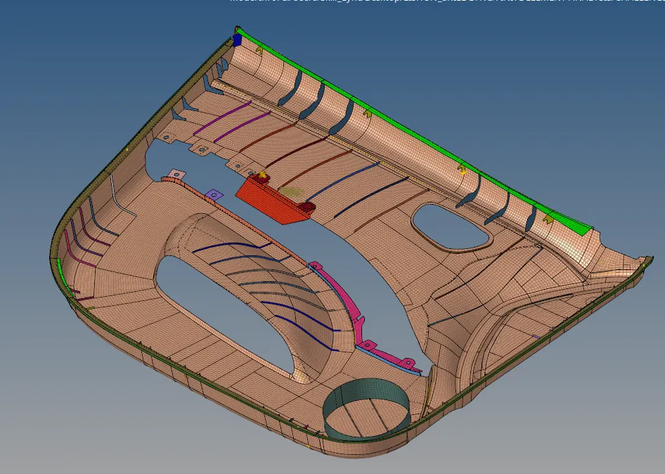
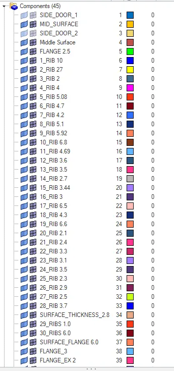
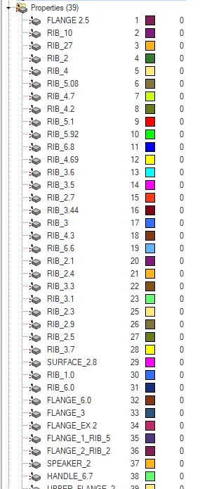
- The next step after completing the meshing is the assigning the thickness to each and every parts which have varying thickness.This is done by creating a component and rename with the name of the part along with the thickness value(Example:1_RIB_2.5).After creating the component create a propery for the same with thickness as 2.5 and assign the property to the component by rigt clicking on components->Assign and select the property from the drop down box.After goto Tools->Organize->select the elements which have to be moved and select the destination component as 1_RIB_2.5 and click on move.

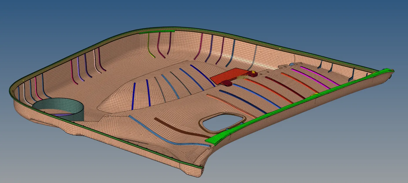
- Similarly gothrough each and every component andassign thickness to it.When assigned with all the thickness and the change the option to 2D detailed Element Representation from traditional element representation, so that the assigned thickness will be reflected into the meshed mid surface which is shown below:
2D Traditional Element Representation:
2D Detailed Element Representation:
CONCLUSION:
The given model or component of Side door panel have been completed by extracting the midsurface which is an exact replica of the parent model and generated the meshing on the whole component with the given quality parameters and a better mesh flow all over the region.The tria percentage of the model is reduced to 1.1 percentage.The tria percentage can be checked in the Page 3 of Quality Index toolbar
