Project 2 Adaptive Cruise Control
Adaptive Cruise Control (ACC) Model Development Report
1. Introduction
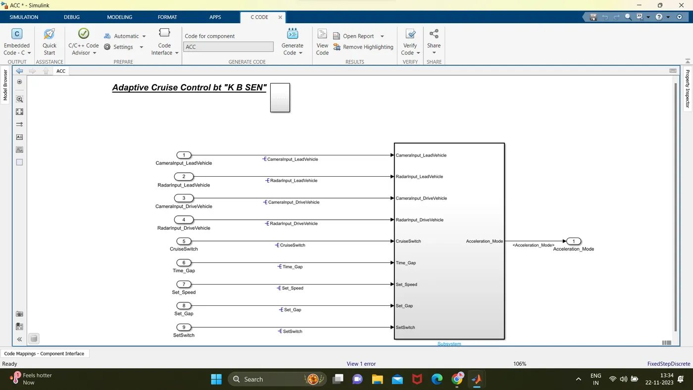
The Adaptive Cruise Control (ACC) feature enhances the driving experience by automatically adjusting the vehicle speed to maintain a safe following distance from the lead vehicle. This report outlines the development of the ACC feature using MATLAB Simulink, adhering to Model-Based Design (MBD) processes.
2. System Architecture
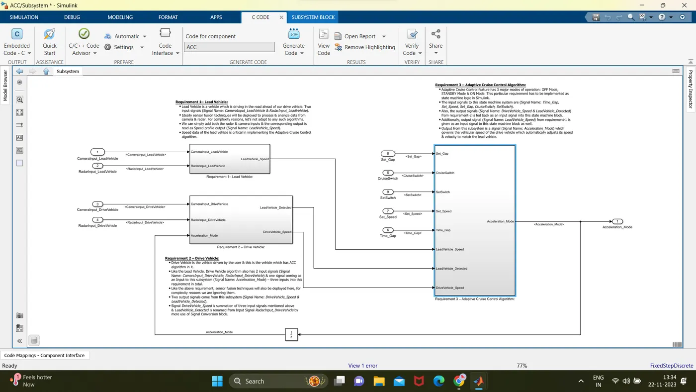
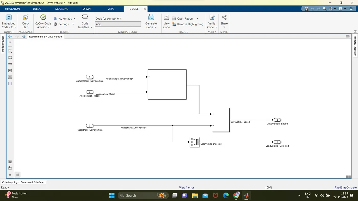
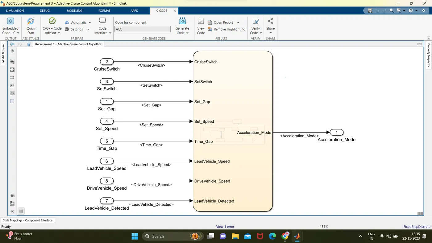
The ACC system is composed of three main requirements: Lead Vehicle, Drive Vehicle, and the ACC Algorithm. The Lead Vehicle module processes inputs from radar and camera sensors to provide the speed profile of the lead vehicle. The Drive Vehicle module incorporates sensor fusion and generates signals representing the speed of the drive vehicle and the detection status of the lead vehicle. The ACC Algorithm, implemented as a state machine, receives inputs and produces an output signal, Acceleration_Mode, which governs the drive vehicle's speed.
3. Model-Based Design (MBD) Processes
The development process follows MBD principles, including Requirement Tagging & Traceability, Signal Line Design Description (SLDD) creation, Configuration Parameter changes, Model Advisor checks, and Code Generation.
- Requirement Tagging & Traceability: Each requirement is tagged and traced throughout the model, ensuring a clear understanding of its implementation.
- SLDD Creation: Signal Line Design Descriptions are created for each signal, defining its purpose and behavior.
- Configuration Parameters: "Support Floating Numbers" is enabled under Code Generation settings.
- Code Generation: Embedded Coder is utilized to generate code. Storage classes for signals are appropriately set, and a sample time of 0.01s is chosen for all signals.
4. Lead Vehicle Requirement
The Lead Vehicle module processes radar and camera inputs to provide the speed profile of the lead vehicle, crucial for the ACC algorithm.
5. Drive Vehicle Requirement
The Drive Vehicle module fuses sensor inputs, producing signals representing the drive vehicle's speed and the detection status of the lead vehicle.
6. ACC Algorithm Requirement
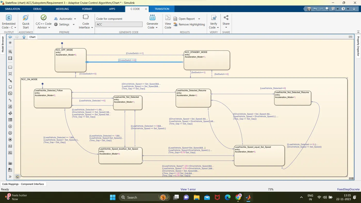
The ACC Algorithm is implemented as a state machine with three major modes: OFF, STANDBY, and ON. It takes inputs such as Time_Gap, Set_Speed, Set_Gap, CruiseSwitch, SetSwitch, and outputs the Acceleration_Mode signal.
7. State Machine Logic
- ACC OFF MODE (3a): The default state with Acceleration_Mode set to 0. Transition conditions depend on CruiseSwitch.
- ACC STANDBY MODE (3b): Activated by CruiseSwitch and SetSwitch. Transition conditions control state changes.
- ACC ON MODE (3c): Activated by SetSwitch. Six sub-states govern the ACC ON MODE logic.
- LeadVehicle_Detected_Follow (Default): Default state with Acceleration_Mode set to 2. Transition conditions control state changes.
- LeadVehicle_Not_Detected: Acceleration_Mode set to 1. Transition conditions control state changes.
- LeadVehicle_Detected_Resume: Acceleration_Mode set to 3. Transition conditions control state changes.
- LeadVehicle_Not_Detected_Resume: Acceleration_Mode set to 1. Transition conditions control state changes.
- LeadVehicle_Speed_lessthan_Set_Speed: Acceleration_Mode set to 4. Transition conditions control state changes.
- LeadVehicle_Speed_equal_Set_Speed: Acceleration_Mode set to 5. Transition conditions control state changes.
8. Conclusion
The ACC model is successfully developed, adhering to MBD processes and meeting the specified requirements. The state machine logic ensures proper control of the ACC feature, allowing the drive vehicle to adapt to the lead vehicle's speed while maintaining safety and comfort. The model is ready for further validation and testing to ensure its robust performance in real-world scenarios.