Project 1 - 40-V to 80-V adjustable output voltage boost reference design for LIDAR applications
Designing a non-synchronous boost controller for automotive applications requires careful consideration of various factors, including layer stackup, trace width, via size, trace length, and PCB layout. Here's how you can address each of the questions:
Layer Stackup:
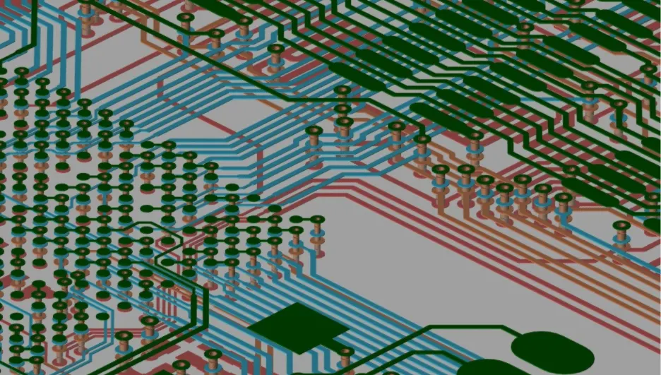
For this application, a minimum of four layers may be suitable to accommodate power planes, signal layers, and ground planes.
A typical stackup might include signal layers sandwiched between power and ground planes to provide better noise immunity, controlled impedance, and thermal management.
Consideration should be given to the thickness and material properties of the dielectric layers to ensure adequate insulation and controlled impedance for high-voltage traces.
Calculating Trace Width, Via Size, and Trace Length:
Trace Width: Use a trace width calculator or PCB design software to calculate the minimum trace width required to carry the maximum current without excessive voltage drop or heating. Ensure that the calculated trace width meets the IPC-2152 or other relevant standards for current-carrying capacity.
Via Size: Determine the via size based on the current-carrying capacity, thermal management requirements, and manufacturability constraints. Consider using larger vias for higher currents and thermal vias for heat dissipation.
Trace Length: The trace length depends on the layout of the PCB and the placement of components. Minimize trace lengths to reduce impedance and signal propagation delays, especially for high-frequency signals.
Drawbacks of Two-Layer PCB:
Limited Routing Space: With only two layers, routing becomes more challenging, especially for complex designs with high component density or dense routing requirements.
Signal Integrity Issues: Inadequate ground plane coverage and routing constraints may lead to signal integrity issues such as crosstalk, electromagnetic interference (EMI), and impedance mismatch.
Poor Power Distribution: Limited power and ground planes in a two-layer PCB may result in higher impedance and poorer power distribution, leading to voltage drops and noise coupling.
Thermal Management: Two-layer PCBs may have limited options for thermal vias and heat dissipation, which can affect the thermal performance of the circuit.
In summary, while a two-layer PCB may be sufficient for simpler designs or low-frequency applications, a four-layer or higher layer count PCB is often preferred for automotive applications requiring high voltage, current, and reliability, such as the non-synchronous boost controller described in the question. Careful consideration of layer stackup, trace width, via size, and PCB layout is essential to meet the performance, reliability, and safety requirements of automotive electronics.