Week-7 Challenge: DC Motor Control
1. A. Explain a MATLAB demo model named ‘Speed control of a DC motor using BJT H-bridge’.
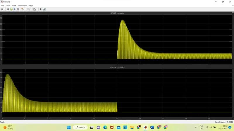
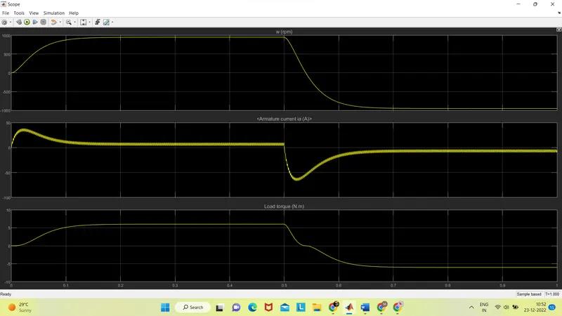
B. Comment on the armature current shoot-up from the scope results.
C. Refer to the help section of ‘The Four-Quadrant Chopper DC Drive (DC7) block’. Compare it with the H-bridge model.
answer:
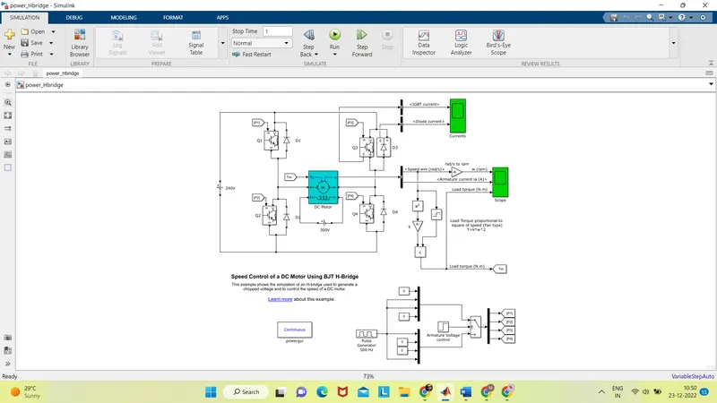
A. Explain a MATLAB demo model named ‘Speed control of a DC motor using BJT H-bridge’.
The "Speed control of a DC motor using BJT H-bridge" demo is a model that demonstrates how to control the speed of a DC motor using a BJT (bipolar junction transistor) H-bridge. The H-bridge is a circuit configuration commonly used to control the direction and speed of a DC motor.
In this demo, the H-bridge is implemented using BJT transistors, which are used to switch the direction of current flow through the motor. The speed of the motor is controlled using pulse width modulation (PWM), which involves rapidly switching the transistors on and off at a high frequency to control the average voltage applied to the motor.
The demo includes a Simulink model that implements the H-bridge and PWM control, as well as a graphical user interface (GUI) that allows the user to control the speed of the motor by adjusting a slider. The GUI also displays real-time data such as the motor speed and current, as well as the PWM duty cycle.
B. Comment on the armature current shoot-up from the scope results
It is not uncommon for the armature current of a DC motor to "shoot up" under certain conditions. This can occur due to a variety of factors, such as an increase in the load on the motor, a sudden change in the voltage applied to the motor, or a fault in the motor or its control system.
If the armature current of a DC motor shoots up suddenly and significantly, it can indicate a problem with the motor or its control system. In some cases, this can cause the motor to become overloaded, which can result in reduced performance or even damage to the motor.
To understand why the armature current of a DC motor might shoot up, it is important to consider the specific conditions under which this behavior is observed. For example, if the armature current shoots up when the load on the motor is increased, this may indicate that the motor is not able to handle the increased load and is becoming overloaded. On the other hand, if the armature current shoots up when the load on the motor is constant, this may indicate a fault in the motor or its control system.
To troubleshoot this issue, it may be helpful to examine the motor and its control system in detail, looking for any signs of damage or malfunction. Additionally, it may be helpful to run diagnostic tests on the motor and its control system to identify the root cause of the problem.
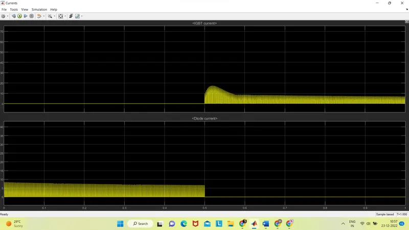
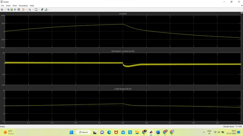
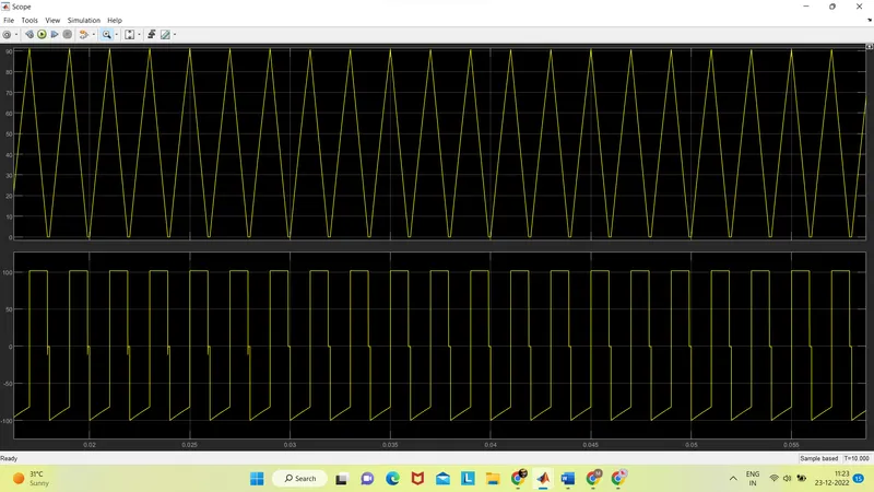
We had observed a significant surge in the waveform at the beginning of the armature current that appeared from above. We shall cut the pulse width modulation's duty cycle from 75% to 50% in order to lessen the armature current's abrupt rise.
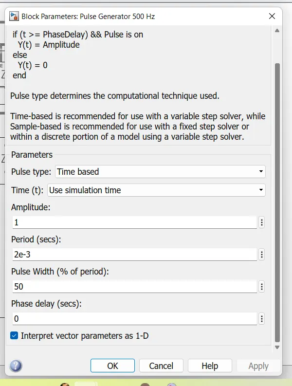
The waveform's output is displayed below.
C. Refer to the help section of ‘The Four-Quadrant Chopper DC Drive (DC7) block’. Compare it with the H-bridge model.
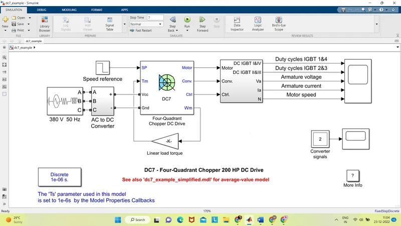
The Four-Quadrant Chopper DC Drive (DC7) block is a Simulink model that represents a four-quadrant DC drive, which is a type of electric motor drive that can operate in all four quadrants of a plane. A four-quadrant drive is capable of operating a DC motor in both the forward and reverse directions, as well as controlling the speed of the motor in both directions.
The DC7 block is designed to provide a simplified, high-level representation of a four-quadrant DC drive, allowing users to model and simulate the behavior of a DC motor and its control system without the need to model the detailed workings of the drive. The block includes a set of input and output ports that allow it to be easily connected to other Simulink blocks and to receive inputs such as speed and torque commands and provide outputs such as motor speed and current.
In contrast, the H-bridge model is a more detailed representation of a DC motor drive that includes a specific implementation of an H-bridge circuit using BJT transistors. The H-bridge model includes a Simulink model of the H-bridge circuit and a graphical user interface (GUI) that allows the user to control the speed of the motor using pulse width modulation (PWM).
Both the DC7 block and the H-bridge model can be used to model and simulate the behavior of a DC motor and its control system. However, the DC7 block provides a more abstract representation of a DC drive, while the H-bridge model includes a specific implementation of an H-bridge circuit and PWM control.
------------------------------------------------------------------------------------------------------------------------------------------------------------------------------------------------------------------------------
2. Develop a 2-quadrant chopper using simulink & explain the working of the same with the relevant results. (Refer to article - Multiquadrant operation of motor )
answer:
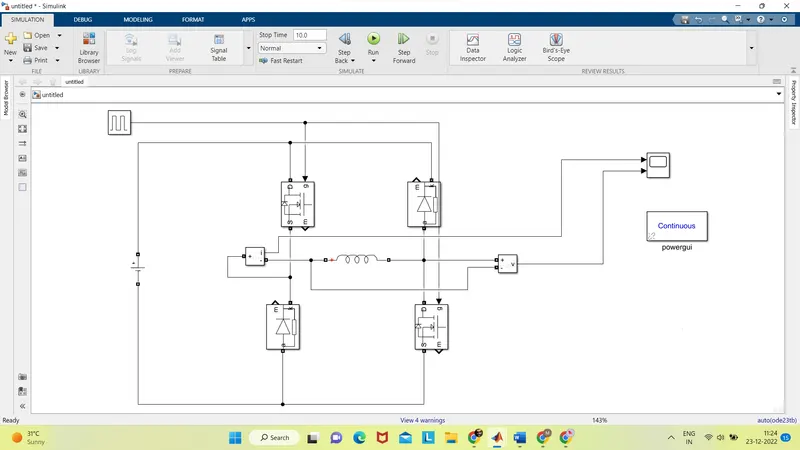
a 2-quadrant chopper is a device that can be used to control the voltage applied to a DC motor. It does this by rapidly switching a DC voltage on and off using pulse width modulation (PWM). By adjusting the duty cycle of the PWM signals, the average voltage applied to the motor can be controlled, which in turn allows the speed of the motor to be controlled. Using Simulink, you can model and simulate the behavior of a 2-quadrant chopper and observe the results using a Scope block.
A two-quadrant chopper is a device that can be used to control the voltage applied to a DC motor by rapidly switching a DC voltage on and off using pulse width modulation (PWM). In this case, the PWM signals have an amplitude of 10, a period of 0.002, and a pulse width of 50%.
When the two-quadrant chopper receives PWM signals with these characteristics, it will switch the DC voltage on and off at a frequency of 500 Hz (1/0.002). The duty cycle of the PWM signals is 50%, which means that the voltage is applied to the motor for half of the period and turned off for the other half. This results in an average voltage applied to the motor of 5 (50% of 10).
The two-quadrant chopper works by switching the DC voltage on and off using a set of transistors or other switching devices. When the voltage is switched on, it is applied to the motor and causes it to rotate. When the voltage is switched off, the motor continues to rotate due to its inertia, but the voltage applied to the motor is zero. By rapidly switching the voltage on and off, the two-quadrant chopper can control the average voltage applied to the motor and thus the speed of the motor.
By adjusting the duty cycle of the PWM signals, the average voltage applied to the motor can be controlled. For example, if the duty cycle is increased to 75%, the average voltage applied to the motor will increase to 7.5 (75% of 10), which will result in the motor rotating at a higher speed. Similarly, if the duty cycle is decreased to 25%, the average voltage applied to the motor will decrease to 2.5 (25% of 10), which will result in the motor rotating at a lower speed.
------------------------------------------------------------------------------------------------------------------------------------------------------------------------------------------------------------------------------
3. Explain in a brief about operation of BLDC motor.
answer :
A brushless DC (BLDC) motor is a type of electric motor that uses a permanent magnet rotor and a three-phase stator to produce rotational motion. Unlike a traditional DC motor, which uses brushes and a commutator to switch the current flow through the rotor windings, a BLDC motor uses electronic commutation to control the current flow through the stator windings.
The operation of a BLDC motor can be divided into four main stages:
-
Startup: When the BLDC motor is first energized, the rotor is stationary and the stator windings are energized in a specific sequence to create a rotating magnetic field. This causes the rotor to start rotating and begin following the rotating magnetic field.
-
Steady-state operation: As the rotor reaches a steady speed, the stator windings are energized in a specific sequence to maintain the rotating magnetic field and keep the rotor rotating. The speed of the rotor is controlled by adjusting the frequency of the current applied to the stator windings.
-
Speed control: To change the speed of the rotor, the frequency of the current applied to the stator windings can be adjusted. Increasing the frequency will cause the rotor to rotate faster, while decreasing the frequency will cause the rotor to rotate slower.
-
Shutdown: To stop the rotor, the current flow through the stator windings can be turned off. This will cause the magnetic field in the stator to disappear, allowing the rotor to come to a stop.
BLDC motors are known for their high efficiency, high power density, and low maintenance requirements. They are commonly used in a variety of applications, including electric vehicles, electric pumps, fans, and robotics.
A brushless DC (BLDC) motor is an electric motor that uses a permanent magnet rotor and a three-phase stator to produce rotational motion. The main components of a BLDC motor are:
-
Rotor: The rotor is the moving part of the motor that rotates around the axis of the motor. In a BLDC motor, the rotor is typically made of a permanent magnet material, such as neodymium, samarium cobalt, or ferrite. The permanent magnet rotor creates a magnetic field that interacts with the magnetic field generated by the stator to produce rotational motion.
-
Stator: The stator is the stationary part of the motor that surrounds the rotor. It consists of a series of winding coils that are energized to create a rotating magnetic field. In a BLDC motor, the stator typically has three phases, each of which is made up of a set of winding coils. The stator windings are energized in a specific sequence to create the rotating magnetic field.
-
Commutation: The commutation system is responsible for switching the current flow through the stator windings in a specific sequence to maintain the rotating magnetic field. In a BLDC motor, the commutation is typically performed electronically using a sensor system and an electronic control unit (ECU).
-
Bearings: The bearings are used to support the rotor and allow it to rotate smoothly. BLDC motors typically use either ball bearings or sleeve bearings.
-
Housing: The housing is the outer casing that encloses the rotor, stator, and other components of the motor. It provides protection for the internal components of the motor and also helps to dissipate heat.
The working principle of a brushless DC (BLDC) motor is based on the interaction between the magnetic field generated by the rotor and the magnetic field generated by the stator. When the stator windings are energized in a specific sequence, they create a rotating magnetic field that causes the rotor to rotate and follow the field.
The speed of the rotor is controlled by adjusting the frequency of the current applied to the stator windings. Increasing the frequency will cause the rotor to rotate faster, while decreasing the frequency will cause the rotor to rotate slower.
In a BLDC motor, the current flow through the stator windings is controlled using electronic commutation. This involves using a sensor system to detect the position of the rotor and switching the current flow through the stator windings in a specific sequence to maintain the rotating magnetic field.
Overall, the working principle of a BLDC motor is based on the interaction between the magnetic fields generated by the rotor and stator, and the control of the current flow through the stator windings using electronic commutation. This allows the motor to operate efficiently and with high power density and low maintenance requirements.
------------------------------------------------------------------------------------------------------------------------------------------------------------------------------------------------------------------------------