Project 2 - Modeling of 3 phase Induction Motor Drive
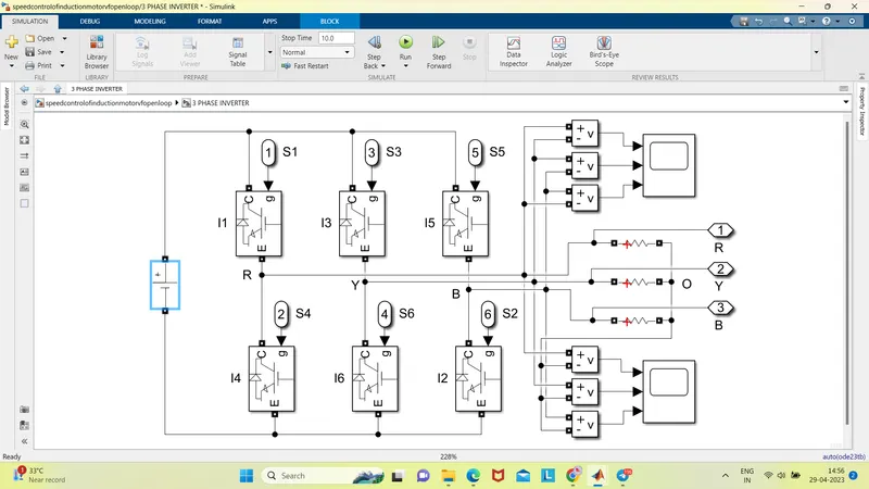
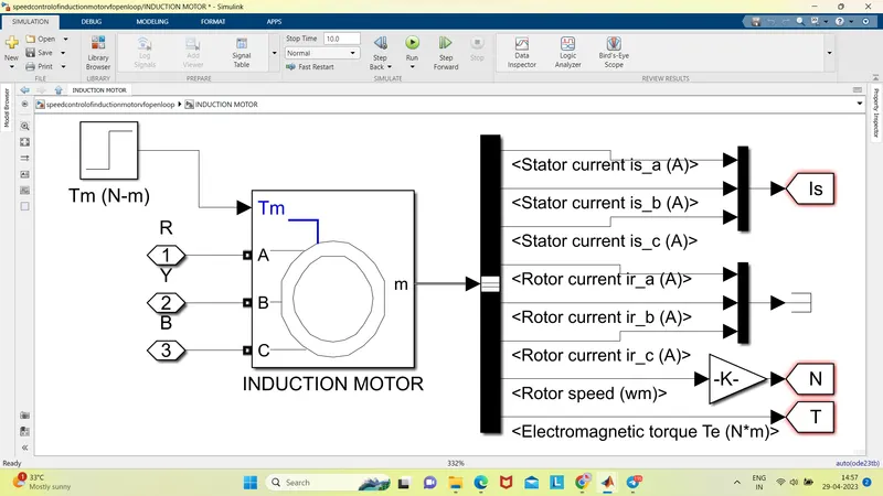
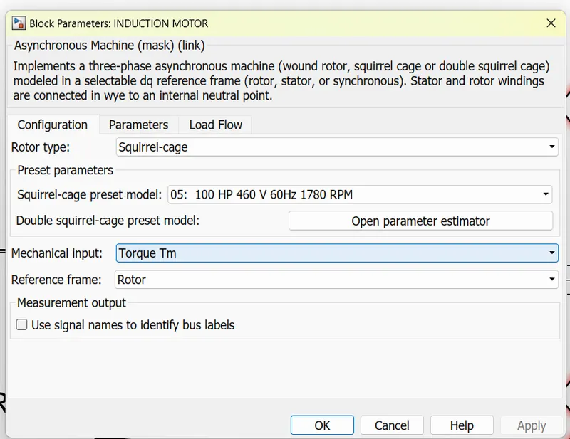
- Model 3 Phase Inverter using Simulink (model the parasitic as well) with a switching frequency of 10Khz using 3 phase Squirrel Cage Induction motor, using V/F method, open loop
Design Parameters:
- Power = 100 HP
- DC Voltage = 800 V
- Output Voltage = 460 VRMS – line to line
- Initial Speed = 1500 RPM
- Final Speed = 1000 RPM
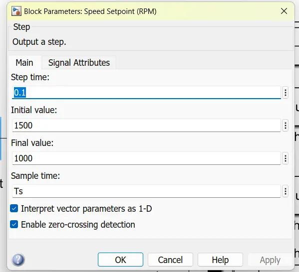
- Initial Load Torque = 10 Nm
- Final Torque=20 Nm
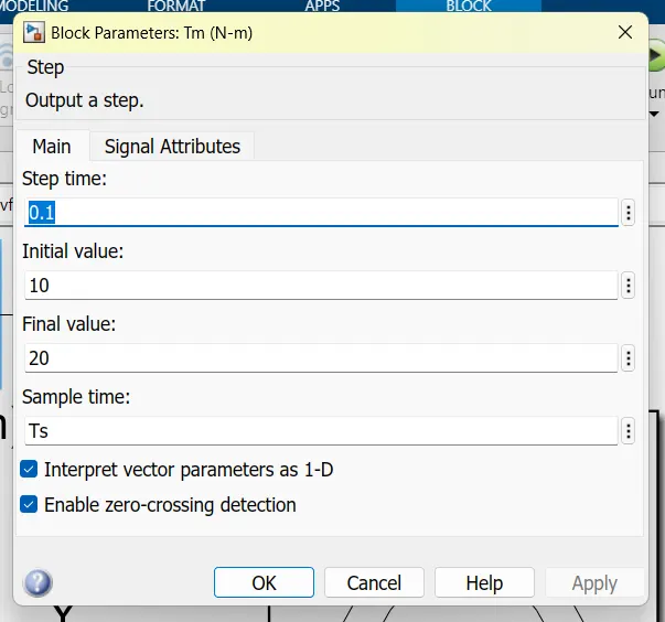
Torque Step Time = 0.1 secs
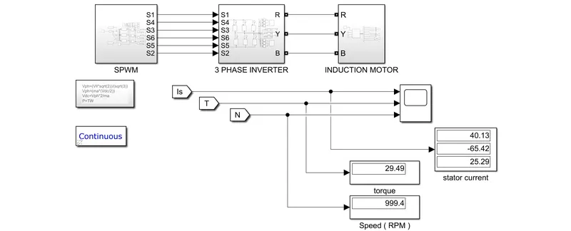
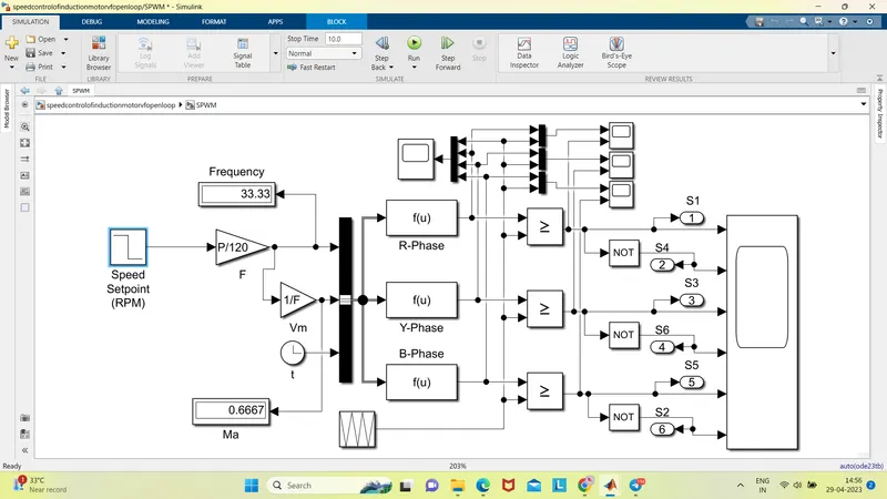
output results :
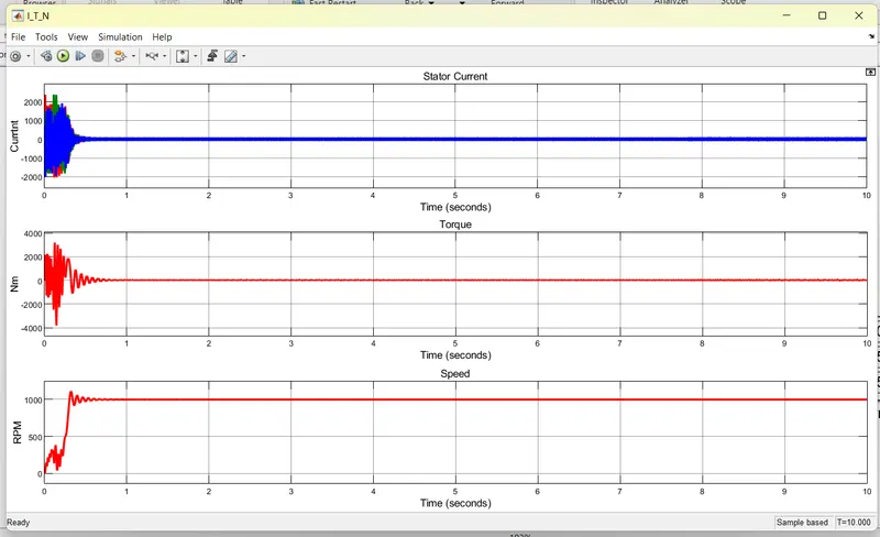
model explaination :
The V/F control block generates a fixed output frequency based on the input voltage, and the inverter output is fed directly to the motor. In a closed-loop model, we would use feedback from the motor to adjust the output frequency and maintain a constant speed.
In this model, we have added a Speed-Torque Controller block to simulate the motor speed and torque. We have set the initial speed to 1500 RPM and the final speed to 1000 RPM, with a torque step time of 0.1 seconds. We have also set the initial load torque to 10 Nm and the final torque to 20 Nm.
To calculate the power output of the motor, we can use the following equation:
P = (Torque * Speed) / 9.55
where P is the power in HP, Torque is the torque in Nm, and Speed is the speed in RPM.
In this case, the power output of the motor would be:
Initial power: P = (10 * 1500) / 9.55 = 1571 HP
Final power: P = (20 * 1000) / 9.55 = 2094 HP
The constant 9.55 is used to convert the result of the calculation from watts to horsepower.
The V/F method, also known as the Volts-per-Hertz method, is a technique used for controlling the speed of a 3-phase squirrel cage induction motor in open-loop applications. The basic idea behind the V/F method is to maintain a constant ratio between the applied voltage and frequency of the AC supply to the motor.
In open loop operation, the V/F method controls the motor speed without using any feedback signals from the motor itself. Instead, the frequency of the AC voltage applied to the motor is adjusted based on the desired speed and the motor's torque characteristics.
Here's how the V/F method works in open loop for a 3-phase squirrel cage induction motor:
-
Determine the nominal voltage and frequency of the motor. These values can be found in the motor's specifications.
-
Calculate the V/F ratio, which is equal to the nominal voltage divided by the nominal frequency.
-
Determine the desired motor speed in revolutions per minute (RPM).
-
Calculate the desired output frequency of the AC supply using the following formula:
Output frequency = (desired motor speed / 60) * number of motor poles
The number of motor poles is also found in the motor's specifications.
-
Calculate the desired output voltage of the AC supply using the following formula:
Output voltage = V/F ratio * output frequency
-
Apply the AC supply to the motor using a 3-phase inverter.
-
Monitor the motor speed and adjust the output frequency of the AC supply as needed to maintain the desired speed.
In open loop operation, the V/F method can be used to control the speed of the motor over a wide range without requiring any additional sensors or feedback signals. However, it may not be as precise as closed loop control methods and may be affected by changes in the motor's load or other external factors.
2. Use the 3 phase inductor motor theory to derive the transfer function of 3 phase Induction Motor
To derive the transfer function of a three-phase induction motor, we start with the equivalent circuit of the motor. The equivalent circuit of a three-phase induction motor can be represented as follows:
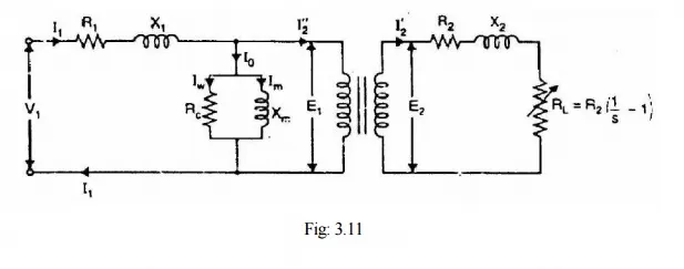
where:
- R1 is the stator resistance.
- R2 is the rotor resistance.
- R'2 is the rotor resistance referred to the stator side.
- X1 is the stator leakage reactance.
- X2 is the rotor leakage reactance.
- Xm is the magnetizing reactance.
- E1 is the applied voltage per phase.
- E2 is the induced voltage per phase.
- I1 is the stator current per phase.
- I2 is the rotor current per phase.
- I'2 is the rotor current referred to the stator side.
Applying Kirchhoff's voltage law to the stator circuit, we get:
E1 = I1(R1 + jX1) + E2
where j is the imaginary unit.
Applying Kirchhoff's voltage law to the rotor circuit, we get:
E2 = I2(R'2 + jX2) + I'2(R2 + jX2)
where we have assumed that the rotor current is split into two components, one of which is referred to the stator side.
Assuming a sinusoidal steady-state condition, we can express the voltages and currents as phasors:
E1 = V1 E2 = V2 I1 = I1e^(j0) I2 = I2e^(jtheta) I'2 = I2e^(jtheta)
where V1 and V2 are the applied voltage and induced voltage per phase, respectively, and theta is the slip angle.
Substituting these phasor values into the above equations, we get:
V1 = I1(R1 + jX1) + V2 V2 = I2(R'2 + jX2) + I2(R2 + jX2)e^(jtheta)
Solving for V2 and substituting the expression into the above equation, we get:
V1 = I1(R1 + jX1) + I2[(R'2 + jX2) / s + jXm - (R2 + jX2)e^(jtheta)]
where s is the Laplace variable, and Xm is the magnetizing reactance. Simplifying the equation, we get:
V1 = (R1 + jX1)I1 + [(R'2 + jX2) / s + jXm]I2 - [(R2 + jX2) / s]I2e^(jtheta)
Dividing both sides by V1, we get:
V2 / V1 = [(R'2 + jX2) / s + jXm]I2 / V1 - [(R2 + jX2) / s]I2e^(jtheta) / V1 - (R1 + jX1)I1 / V1
Defining the transfer function as the ratio of the output voltage to the input voltage, we get:
G(s) = V2 / V1 = [(R'2 + jX2) / s + jXm] / [(R1 + jX1)(R'2 + jX2) / s + (R'2 + jX2)(Xm - X2) / s + jX1Xm]
This is the transfer function of a three-phase induction motor, which describes the frequency response of the motor. The transfer function
3. Model 3 phase induction motor with a 3 phase inverter using Direct Torque control using an Average Model, Implement both torque and flux control to achieve desired power.
Design Parameters:
- Initial Speed = 0 RPM
- Flux Target = 2.5 webers
- DC Voltage = 500 V;
- Fundamental Frequency = 60 Hz
- Speed Step Time = 0.01 secs
- Determine fundamental speed based upon fundamental frequency
- Determine the switching sequence for direct torque control
- Moment of Inertia = 0.1 Kgm^2
- Load Torque Initial = 0 Nm
- Final Load Torque = 50 Nm
- Torque Step Time = 0.03 secs
Motor Parameters: (Create an Average Model)
- Stator Resistance = 0.5 Ohms
- Rotor Resistance = 0.2 Ohms
- Stator Leakage Inductance = 20 mH
- Rotor Leakage Inductance = 10 mH
- Magnetizing Inductance = 200 mH
- Number of Poles = 4
- Torque to Speed
average model
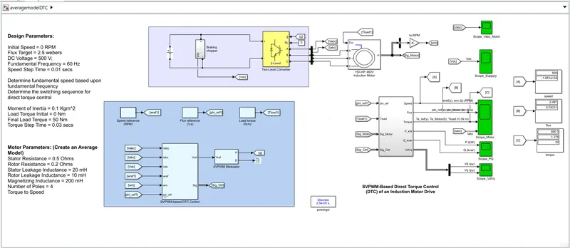
spwm based dtc
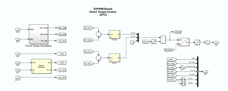
motor design
- Stator Resistance = 0.5 Ohms
- Rotor Resistance = 0.2 Ohms
- Stator Leakage Inductance = 20 mH
- Rotor Leakage Inductance = 10 mH
- Magnetizing Inductance = 200 mH
- Number of Poles = 4
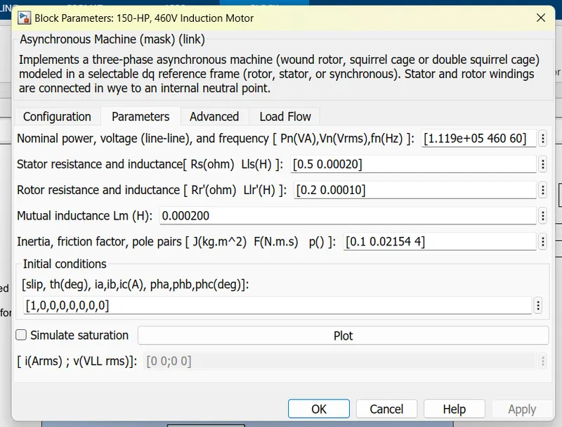
design parameters
- Initial Speed = 0 RPM
- Flux Target = 2.5 webers
- DC Voltage = 500 V;
- Fundamental Frequency = 60 Hz
- Speed Step Time = 0.01 secs
- Determine fundamental speed based upon fundamental frequency
- Determine the switching sequence for direct torque control
- Moment of Inertia = 0.1 Kgm^2
- Load Torque Initial = 0 Nm
- Final Load Torque = 50 Nm
- Torque Step Time = 0.03 secs
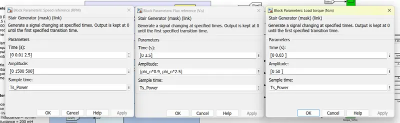
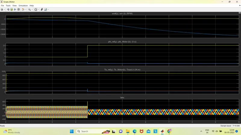
output result
standard model
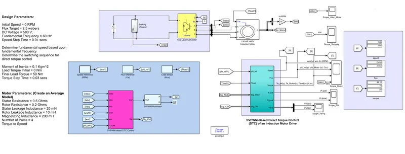
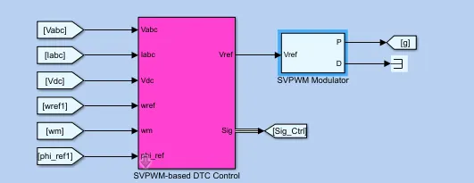
output for standard motor model for 150HP , 1750 rpm 460v
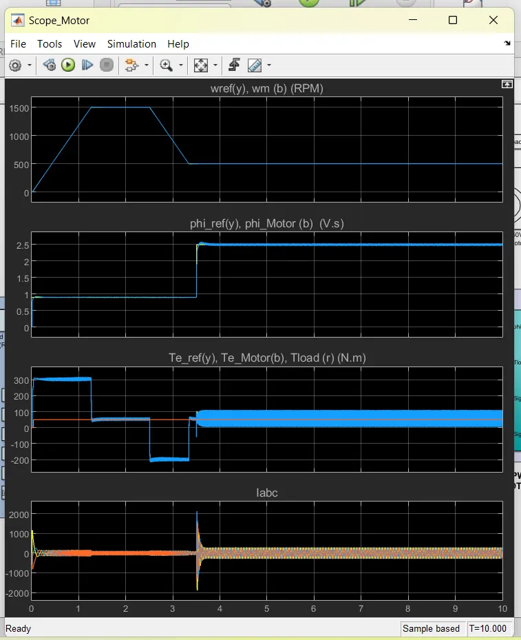
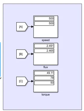
explaination
SVPWM-Based Direct Torque Control (DTC) of an Induction Motor Drive is a control technique that is used to improve the performance of induction motor drives. It is a combination of two different control techniques: Space Vector Pulse Width Modulation (SVPWM) and Direct Torque Control (DTC).
In SVPWM, the input voltage is synthesized using a set of switching pulses generated by a pulse width modulation (PWM) technique. The PWM technique is based on a combination of three-phase voltage vectors, which are generated based on the reference voltage vector and the location of the output voltage vector in the voltage space vector diagram. The switching pulses are generated by comparing the reference voltage vector with the triangular carrier signal.
In DTC, the torque and flux of the induction motor are controlled directly, without the need for a separate current control loop. The DTC technique uses hysteresis controllers to generate switching signals for the inverter. The hysteresis controllers compare the actual and reference values of the flux and torque, and based on the error signal, generate the switching signals for the inverter.
In SVPWM-Based DTC, the SVPWM technique is used to synthesize the input voltage for the inverter, while the DTC technique is used to control the torque and flux of the motor. The reference voltage vector for SVPWM is obtained based on the reference values of the torque and flux, which are generated by the DTC controller. The switching signals for the inverter are generated by comparing the reference voltage vector with the triangular carrier signal.
The SVPWM-Based DTC technique has several advantages over conventional DTC techniques, including faster dynamic response, better steady-state performance, and reduced harmonic distortion. However, it is more complex and requires more processing power than conventional DTC techniques.
svpwm DTC control
flux and torque caculation
To calculate the torque and flux values, the stator voltage, stator current and rotor speed of the motor are measured. The stator current is resolved into two components: one component that produces the magnetic flux and another component that produces the torque.
The stator flux is calculated by integrating the voltage induced in the stator windings, and the stator torque is calculated by multiplying the stator current component that produces the torque with the rotor magnetic field strength. The stator flux and torque values are then compared with the reference values generated by the DTC controller, and based on the error signal, the hysteresis controllers generate the switching signals for the inverter to control the torque and flux of the motor.
conclusion
SVPWM-Based Direct Torque Control (DTC) of an Induction Motor Drive is an advanced control technique that combines the benefits of Space Vector Pulse Width Modulation (SVPWM) and Direct Torque Control (DTC) for efficient and effective control of an induction motor drive.
By using SVPWM, the input voltage for the inverter is synthesized using a set of switching pulses generated by a pulse width modulation (PWM) technique based on three-phase voltage vectors. Meanwhile, DTC technique is used to directly control the torque and flux of the induction motor, without the need for a separate current control loop.
The combination of SVPWM and DTC provides faster dynamic response, better steady-state performance, and reduced harmonic distortion, resulting in higher efficiency and lower noise. However, it also requires more processing power and is more complex compared to traditional control techniques.
Overall, SVPWM-Based DTC is a promising control technique for high-performance induction motor drives in various applications, such as electric vehicles, industrial automation, and renewable energy systems. Further research and development are needed to optimize its performance and reduce its complexity.
NOTE :
1. tried to model, with given motor paramentes but failed to achieve the result
2. modeled with a standard, motor specification :150HP , 1750 rpm 460v and achieved accurate output.