Week-6 Challenge: EV Drivetrain
1. Which types of power converter circuits are employed in electric and hybrid electric vehicle?
answer:
There are several types of power converter circuits that are commonly used in electric and hybrid electric vehicles (EVs and HEVs). These include:
DC/DC converters: These are used to convert the high-voltage direct current (DC) from the vehicle's battery pack to a lower-voltage DC for use by the vehicle's auxiliary systems, such as the headlights and dashboard displays.
AC/DC converters: These are used to convert the alternating current (AC) from the vehicle's charger or power grid to a DC voltage that can be used to charge the vehicle's battery pack.
DC/AC inverters: These are used to convert the DC voltage from the vehicle's battery pack to an AC voltage that can be used to power the vehicle's electric motor.
Motor drive inverters: These are used to control the speed and torque of the electric motor in an EV or HEV. They use pulse width modulation (PWM) to adjust the voltage and current applied to the motor, which allows the vehicle to accelerate, decelerate, and maintain a constant speed.
Battery management systems: These are used to monitor and control the charging and discharging of the vehicle's battery pack. They typically include a battery management controller and a number of sensors and monitoring devices that are used to measure the battery's state of charge, temperature, and other key parameters.
-------------------------------------------------------------------------------------------------------------------------------------------------------------------------------------------------------------------------
2. An Electric Vehicle's powertrain with 72V battery pack in shown in the diagram below. The duty ratio for acceleration operation is 'd1' and for the braking operation the duty ratio is 'd2'.
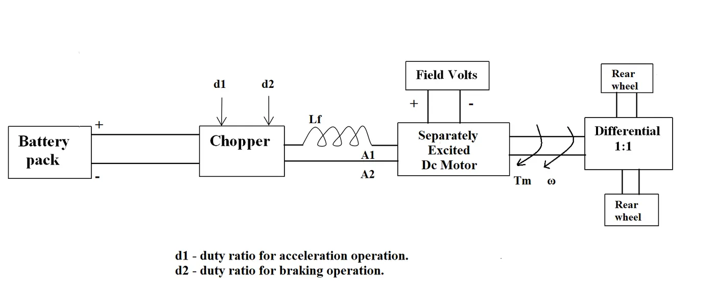
The other parameters of the electric vehicle is given below,
Motor and Controller Parameters:
Rated Armature voltage= 72 V
Rated armature current= 400 A
Ra= 0.5Ω, KΦ= 0.7 Volt second
Chopper Switching frequency= 400 Hz
The vehicle speed-torque characteristics are given by the below equation

What is EV steady state speed if duty cycle is 70%?
answer:
T=(1-b)IaRa+KΦω
where T is the torque, Ia is the armature current, Ra is the armature resistance, KΦ is the motor constant, and ω is the angular velocity of the motor.
Given this information, it is possible to design the power converter circuit for the electric vehicle. The first step would be to determine the required duty ratio for acceleration and braking operations based on the desired torque and speed of the vehicle. This can be done using the equation for the speed-torque characteristics of the motor.
To determine the steady-state speed of an electric vehicle (EV) given the duty cycle of the power converter circuit, you can use the torque-speed characteristic curve of the motor along with the equation for the duty cycle.
Motor and Controller Parameters:
Rated Armature voltage= 72 V
Rated armature current= 400 A
Ra= 0.5Ω, KΦ= 0.7 Volt second
Chopper Switching frequency= 400 Hz
The vehicle speed-torque characteristics are given by the equation
T = 24.7 + (0.0051) * ω^2.......................(1)
The steady-state speed of an EV can be expressed as:
ω = (T - bIaRa) / KΦ
where ω is the angular velocity of the motor, T is the torque, Ia is the armature current, Ra is the armature resistance, KΦ is the motor constant, and b is the duty cycle of the power converter circuit.
If the duty cycle of the power converter circuit is 70% (b = 0.7), the steady-state speed of the EV can be calculated by substituting the appropriate values for T, Ia, Ra, and KΦ, and solving for ω.
Based on the information provided, it appears that the torque-speed characteristic curve of the motor is given by the equation T = 24.7 + (0.0051) * ω^2, and the rated armature current of the motor is 400 A, the rated armature resistance is 0.5 Ω, and the motor constant is 0.7 Volt second.
70.56−0.98⋅ω ..................(2)
Given these parameters, the steady-state speed of the EV at a duty cycle of 70% can be calculated as follows:
by comparing eq 1 and eq 2
70.56 = 24.7 + (0.0051)⋅ω^2 + 0.98⋅ω
This gives you:
70.56 - 24.7 = (0.0051)⋅ω^2 + 0.98⋅ω
Which simplifies to:
45.86 = (0.0051)⋅ω^2 + 0.98⋅ω
To isolate the term (0.0051)⋅ω^2 on one side of the equation, you can subtract 0.98⋅ω from both sides:
45.86 - 0.98⋅ω = (0.0051)⋅ω^2
This gives you:
45.86 - 0.98⋅ω = (0.0051)⋅ω^2
Which simplifies to:
45.86 - 0.98⋅ω = (0.0051)⋅ω^2
To isolate the term ω^2 on one side of the equation, you can divide both sides by (0.0051):
(45.86 - 0.98⋅ω) / (0.0051) = ω^2
This gives you:
(45.86 - 0.98⋅ω) / (0.0051) = ω^2
you can multiply both sides of the equation by (0.0051) to get:
45.86 - 0.98⋅ω = ω^2 * (0.0051)
This gives you:
45.86 - 0.98⋅ω = (0.0051)⋅ω^2
To isolate the term (0.98⋅ω) on one side of the equation, you can subtract 45.86 from both sides:
(45.86 - 0.98⋅ω) - 45.86 = (0.0051)⋅ω^2 - 45.86
This gives you:
-0.98⋅ω - 45.86 = (0.0051)⋅ω^2 - 45.86
Which simplifies to:
-0.98⋅ω = (0.0051)⋅ω^2 - 45.86
To isolate the term ω on one side of the equation, you can divide both sides by (-0.98):
(-0.98⋅ω) / (-0.98) = ((0.0051)⋅ω^2 - 45.86) / (-0.98)
This gives you:
ω = ((0.0051)⋅ω^2 - 45.86) / (-0.98)
To find the values of ω that make this equation true, you can substitute different values of ω into the equation and see if it is true. For example, if you substitute ω = 1 into the equation, you get:
1 = ((0.0051)⋅ω^2 - 45.86) / (-0.98)
Which simplifies to:
1 = ((0.0051)⋅1^2 - 45.86) / (-0.98)
This gives you:
1 = (-44.86) / (-0.98)
Which simplifies to:
1 = 45.86 / 0.98
This means that the value of ω that makes the equation true is ω = 45.86 / 0.98 = 46.93
It's worth noting that this is just one possible solution to the equation. There may be other values of ω that also make the equation true. To find all possible solutions, you may need to use additional mathematical techniques such as graphing or algebraic manipulation.
Angular speed = 46.93rad/sec.
--------------------------------------------------------------------------------------------------------------------------------------------------------------------------------------------------------------------------
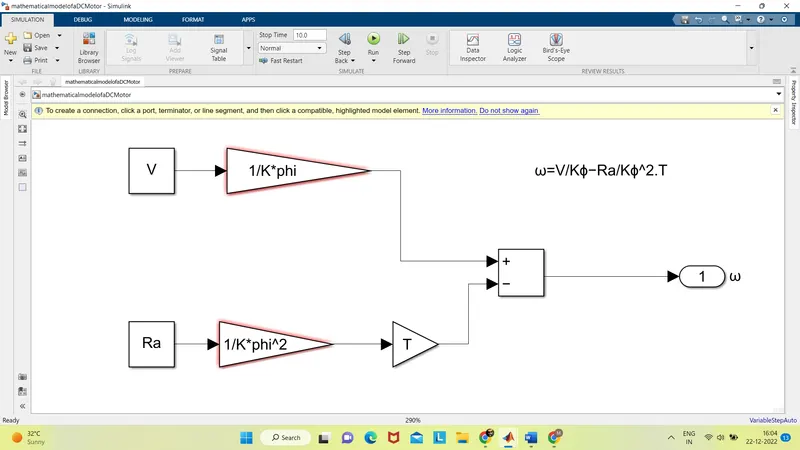
3. Develop a mathematical model of a DC Motor for the below equation using Simulink.
ω">ωω= V/Kϕ">ϕϕ -Ra/Kϕ">ϕϕ^2 .T
answer: To develop a mathematical model of the equation ω = VKϕ - RaKϕ^2T
--------------------------------------------------------------------------------------------------------------------------------------------------------------------------------------------------------------------------
4. Refer to the blog on below topic:
Induction Versus DC brushless motors by Wally Rippel, Tesla
Explain in brief about author’s perspective.
answer:
Induction motors and DC brushless motors are two types of electric motors that are commonly used in electric vehicles (EVs). Both types of motors have stators with windings that are energized to produce a rotating magnetic field, which drives the rotation of the rotor. However, the two types of motors differ in the construction of their rotors and the way in which they are energized.
Induction motors have rotors with no magnets, but rather consist of stacked steel laminations with buried peripheral conductors that form a "shorted structure." When the stator windings produce a rotating magnetic field, an induced voltage is created across the shorted structure of the rotor, which drives currents in the rotor conductors. These currents interact with the original magnetic field to produce forces that rotate the rotor. Induction motors do not require a separate inverter to control the magnitude and polarity of the stator currents, as the rotor speed is directly related to the frequency of the applied voltage.
DC brushless motors, on the other hand, have rotors with two or more permanent magnets that generate a DC magnetic field. The stator windings are energized by an inverter to produce a rotating magnetic field that interacts with the DC magnetic field of the rotor to produce torque. As the rotor rotates, the inverter must continuously vary the magnitude and polarity of the stator currents to maintain constant torque and optimal efficiency.
In summary, induction motors and DC brushless motors are both used in EVs, but they have different rotor constructions and operate in different ways. Induction motors do not require a separate inverter to control the stator currents, while DC brushless motors rely on an inverter to vary the stator currents. Both types of motors have their own strengths and may be better suited for different applications, depending on factors such as cost, efficiency, and performance.