Project 1 (Mini Project on Vehicle Direction Detection
Here's an overview of the requirements and the steps involved in your project:
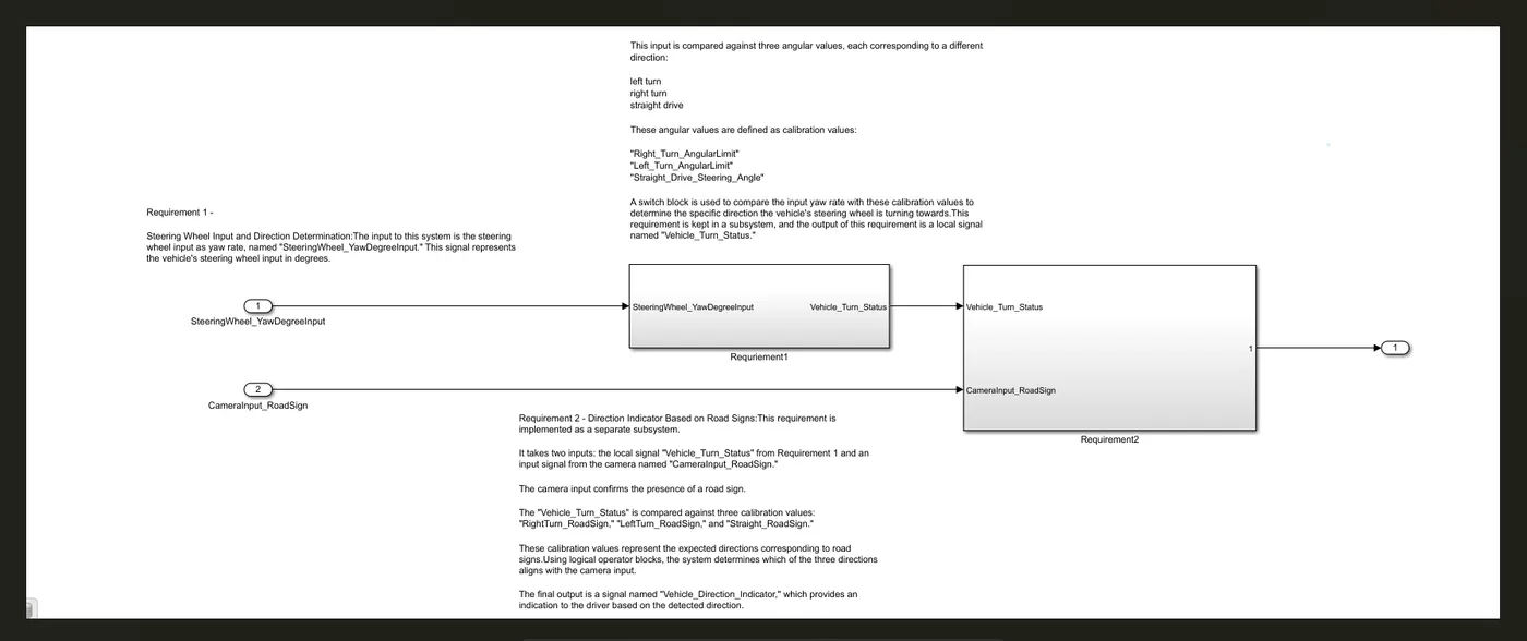
Requirement 1 - Steering Wheel Input and Direction Determination:
- The input to this system is the steering wheel input as yaw rate, named "SteeringWheel_YawDegreeInput." This signal represents the vehicle's steering wheel input in degrees.
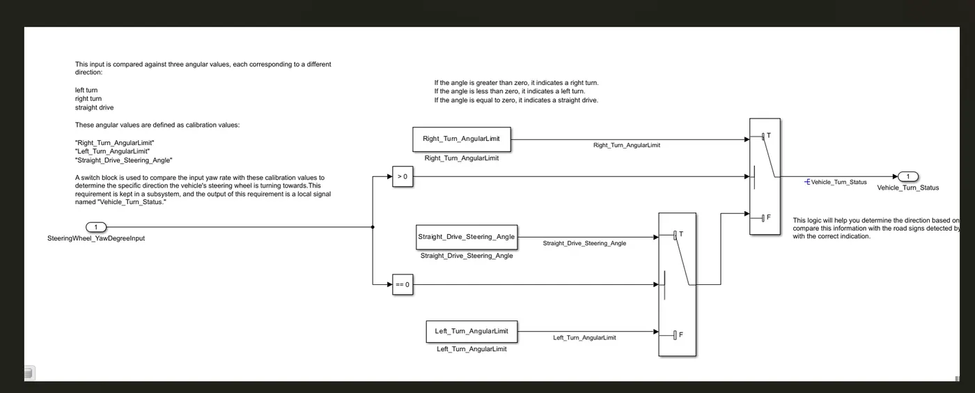
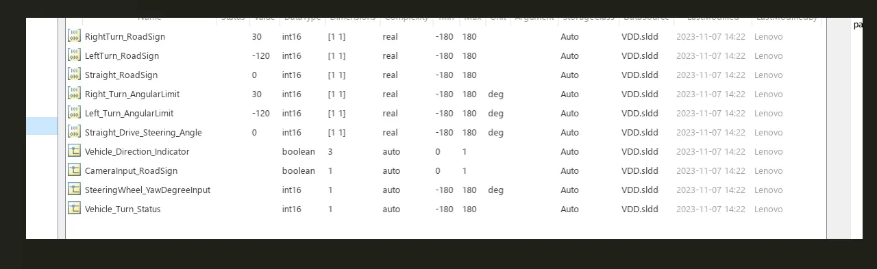
- This input is compared against three angular values, each corresponding to a different direction: left turn, right turn, and straight drive. These angular values are defined as calibration values: "Right_Turn_AngularLimit," "Left_Turn_AngularLimit," and "Straight_Drive_Steering_Angle."
- A switch block is used to compare the input yaw rate with these calibration values to determine the specific direction the vehicle's steering wheel is turning towards.
- This requirement is kept in a subsystem, and the output of this requirement is a local signal named "Vehicle_Turn_Status.
If the angle is greater than zero, it indicates a right turn.
If the angle is less than zero, it indicates a left turn.
If the angle is equal to zero, it indicates a straight drive.
To implement this logic in your MATLAB Simulink model, you can use relational operators and logical blocks. Here's how you can set it up:
Use a Relational Operator block to compare the angle (SteeringWheel_YawDegreeInput) with zero and determine if it's greater, less, or equal to zero.
Connect the output of the Relational Operator block to a Logical Operator block (e.g., an OR block) for each condition (greater, less, equal).
For the greater condition, if the output of the Relational Operator is true, it indicates a right turn. For the less condition, if the output is true, it indicates a left turn. For the equal condition, if the output is true, it indicates a straight drive.
Connect the outputs of the Logical Operator blocks to appropriate indicators or signals, such as "RightTurn_RoadSign," "LeftTurn_RoadSign," and "Straight_RoadSign" (based on the logic you provided).
This logic will help you determine the direction based on the input angle. You can then compare this information with the road signs detected by the camera to provide the driver with the correct indication. Please make sure to adjust the logic and signals in your Simulink model according to the specific requirements and details of your project
Requirement 2 - Direction Indicator Based on Road Signs:
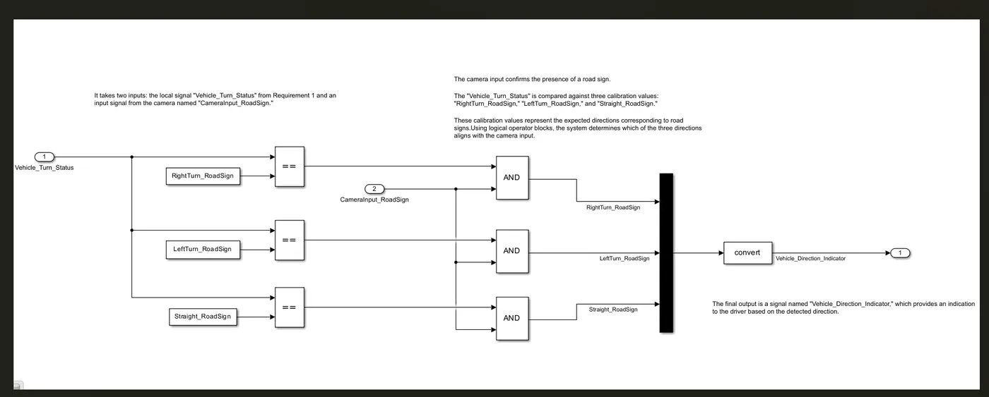
- This requirement is implemented as a separate subsystem.
- It takes two inputs: the local signal "Vehicle_Turn_Status" from Requirement 1 and an input signal from the camera named "CameraInput_RoadSign." The camera input confirms the presence of a road sign.
- The "Vehicle_Turn_Status" is compared against three calibration values: "RightTurn_RoadSign," "LeftTurn_RoadSign," and "Straight_RoadSign." These calibration values represent the expected directions corresponding to road signs.
- Using logical operator blocks, the system determines which of the three directions aligns with the camera input.
- The final output is a signal named "Vehicle_Direction_Indicator," which provides an indication to the driver based on the detected direction.
Signals and Calibration Data:
- Various signals and calibration data are defined in the project. These include:
- Steering wheel input signal ("SteeringWheel_YawDegreeInput") in degrees.
- Camera input signal ("CameraInput_RoadSign") as a Boolean value.
- Local signal for vehicle turn status ("Vehicle_Turn_Status") in degrees.
- Calibration values for angular limits and road signs.
- The output signal "Vehicle_Direction_Indicator" as a Boolean value to indicate the detected direction.