Project-1: Modelling an electric Car with Li-ion battery
Final Project: Design of an Electric Vehicle
Create a MATLAB model of electric car which uses lithium ion battery and suitable motor. Choose suitable blocks from Simscape or Powertrain block set. Implement the vehicle speed control using PI controller and generate brake and accelerator commands. Avoid using readymade driver block for speed control.
(report is added as document )
answer :
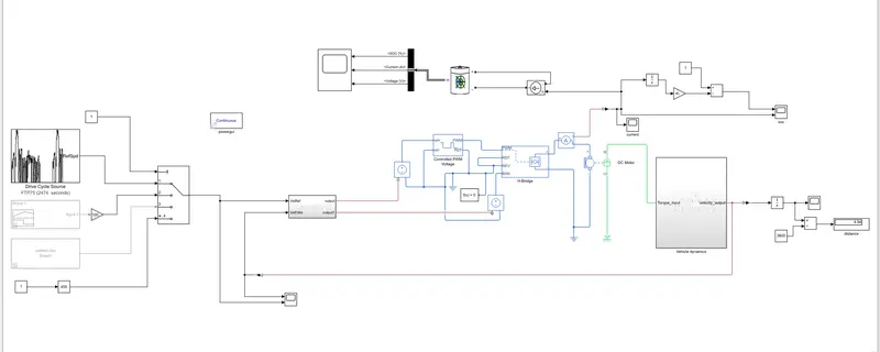
"The purpose of this final project is to design an electric vehicle that meets the needs of a specific market or user group. The final product will be a functional prototype design related to real world system of the electric vehicle, complete with all necessary components and systems.
drive cycle source
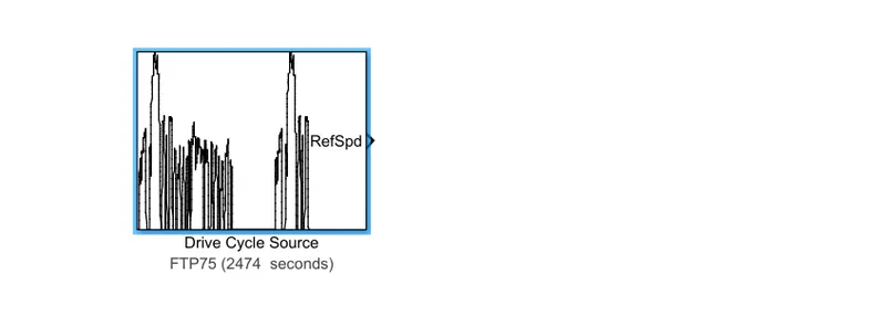
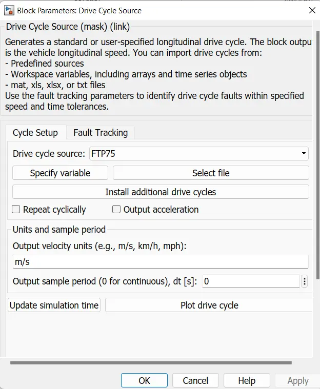
a drive cycle can be represented as a set of time-series data, with each data point representing the vehicle's speed, acceleration, or power demand at a particular point in time. This data can then be used to simulate and analyze the vehicle's performance using various modeling and analysis tools.here, Drive cycles can be created and customized to represent a wide range of driving scenarios, from highway cruising to city driving to aggressive acceleration and braking. They can be used to evaluate a variety of vehicle performance parameters, such as fuel economy, range, emissions, and vehicle dynamics.
parameters
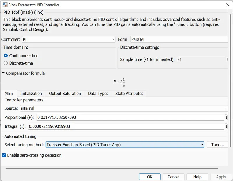
replacing Longitudinal Driver with normal pi controller
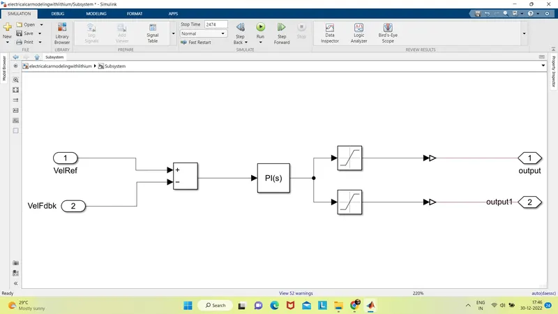
A PI (proportional-integral) controller is a type of control system that uses both proportional and integral control to achieve a desired output. In Simulink, a PI controller can be implemented using the "PID Controller" block, which allows you to specify the proportional and integral gains.
To use a PI controller in the longitudinal driver of a Simulink model, you would first need to determine the desired behavior of the system. This could include things like maintaining a constant speed, following a reference trajectory, or responding to external inputs.
Once you have determined the desired behavior of the system, you can then specify the proportional and integral gains for the PI controller in the "PID Controller" block. The proportional gain determines the strength of the controller's response to the error between the desired output and the current output, while the integral gain determines the strength of the controller's response to the integral of the error over time.
To use the PI controller in your Simulink model, you would connect the output of the "PID Controller" block to the input of the system you want to control, and connect the error signal (the difference between the desired output and the current output) to the "Error" input of the "PID Controller" block. You can then simulate the model to see how the PI controller affects the behavior of the system.
It is important to note that proper tuning of the proportional and integral gains is crucial for the PI controller to function effectively. If the gains are not properly tuned, the system may exhibit unstable behavior or poor performance.
parameter
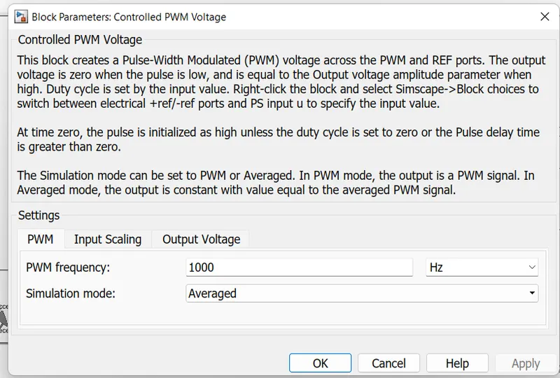
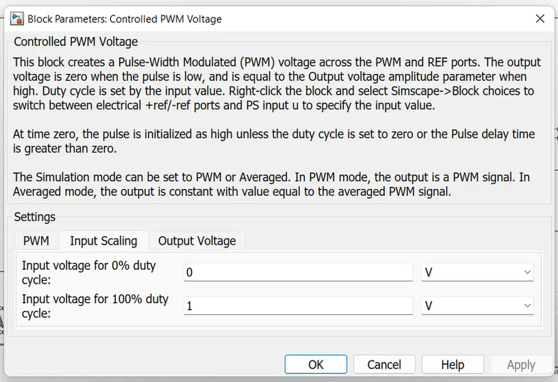
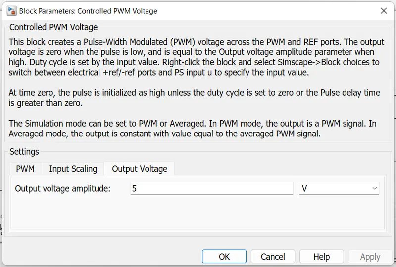
controlled PWM voltage
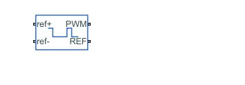
pulse width modulation (PWM) is a technique that can be used to control the voltage applied to an electric motor in order to control its speed and torque. PWM works by rapidly switching the voltage applied to the motor on and off at a high frequency, with the duty cycle (i.e., the proportion of time that the voltage is applied) determining the average voltage applied to the motor. By adjusting the duty cycle, the PWM signal can effectively control the average voltage applied to the motor, and thus its speed and torque.
parameters
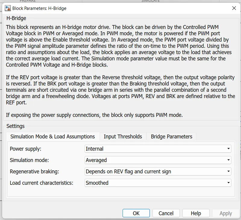
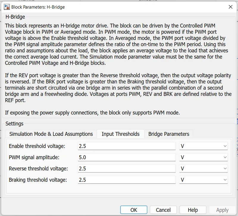
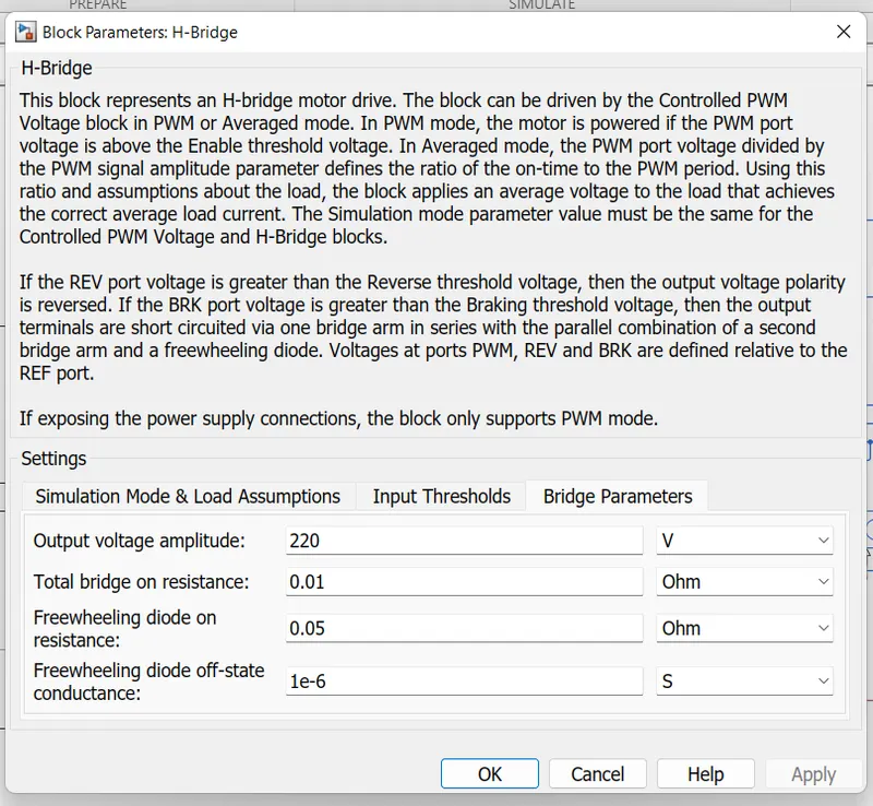
H bridge

An H-bridge is a type of circuit that is commonly used to control the direction and speed of electric motors, including in electric vehicle (EV) applications. It consists of four switching elements (usually transistors or MOSFETs) arranged in a "H" shape, with the motor connected between the two branches of the H. By controlling the switching elements, the H-bridge can control the direction and speed of the motor by applying voltage to different pairs of terminals.
To control the direction of the motor, the H-bridge can apply voltage to either the "high" or "low" side of the motor. For example, to rotate the motor in one direction, the H-bridge can apply voltage to the high side of the motor, while to rotate it in the opposite direction, it can apply voltage to the low side. To control the speed of the motor, the H-bridge can pulse width modulate (PWM) the voltage applied to the motor, effectively varying the average voltage and thus the speed of the motor.
parameters
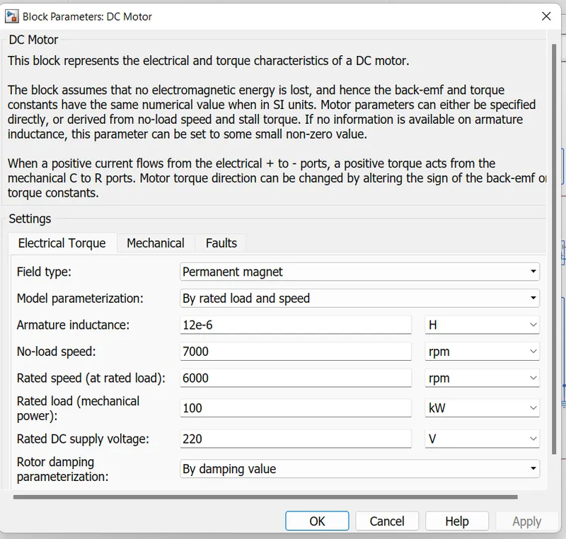
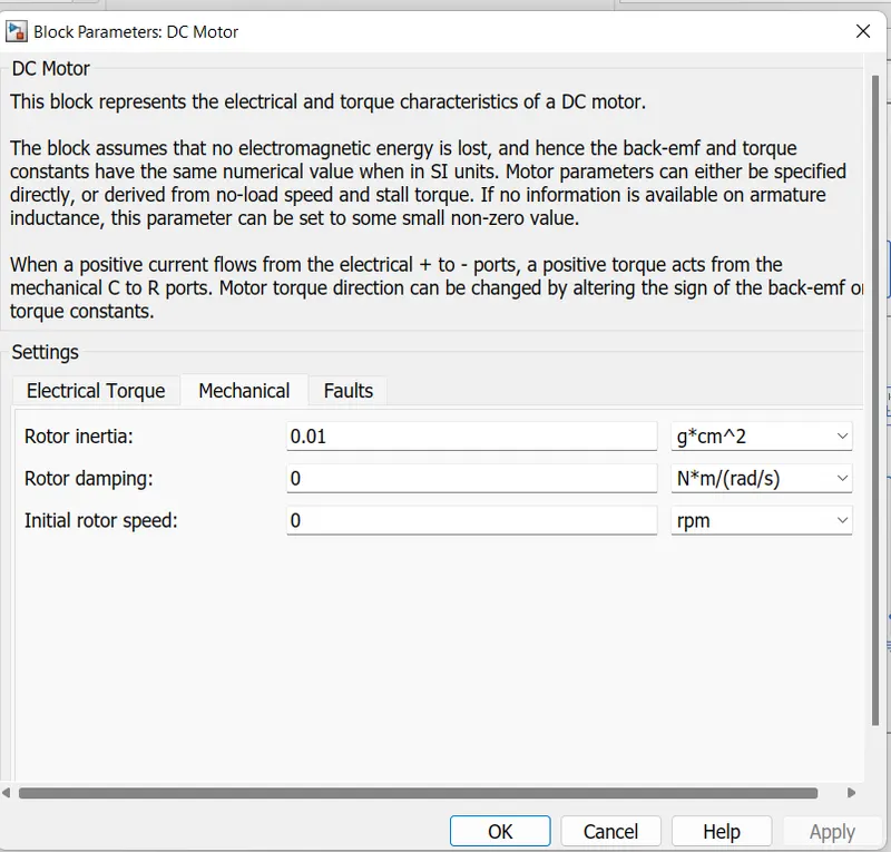
DC Motor
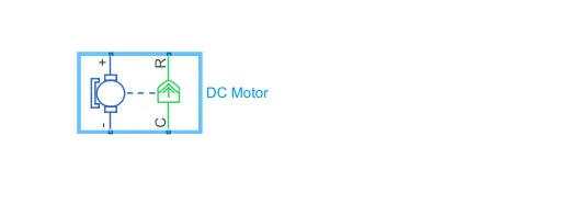
A direct current (DC) motor is a type of electric motor that is commonly used in electric vehicle (EV) applications. It consists of a stator, or stationary part of the motor, and a rotor, or moving part of the motor, which rotates when an electric current is applied to the stator. The direction and speed of the rotor's rotation can be controlled by adjusting the magnitude and polarity of the current applied to the stator.
To control the DC motor in SIMULINK, an external voltage or current source can be applied to the motor's terminals, either directly or through an H-bridge circuit or other control scheme. The behavior and performance of the motor can then be analyzed and evaluated using a variety of analysis and visualization tools, such as scope and plot blocks.
parameters
battery ( using lithium ion battery )

The battery is a key component in the design of an electric vehicle (EV), as it stores and supplies the electrical energy that powers the vehicle's motors and other electrical systems.
-
Performance evaluation: A battery model can be used to evaluate the performance of the battery under different operating conditions and usage scenarios, such as discharge rate, capacity, and efficiency. This can help optimize the battery's design and performance for the specific EV application.
-
Energy management: A battery model can be used in conjunction with other EV models and algorithms to optimize the overall energy management of the EV, including maximizing range and minimizing energy consumption.
-
State of charge (SOC) estimation: A battery model can be used to estimate the SOC of the battery in real-time, which can be important for ensuring that the battery has sufficient energy for the desired driving range and for maximizing the battery's lifetime.
-
Safety analysis: A battery model can be used to evaluate the safety of the battery and its integration into the EV, including analyzing the risk of thermal runaway or other failure modes.
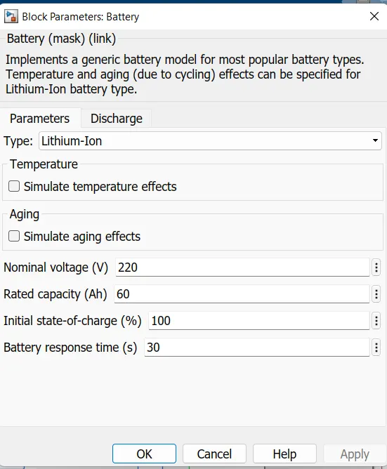
In electric vehicle (EV) design, lithium-ion batteries are commonly used to store and supply electrical energy to the vehicle's motor. In Simulink, you can model the behavior of a lithium-ion battery by using blocks that represent the battery's key characteristics, such as its capacity, internal resistance, and state of charge (SOC).
To model the working of a lithium-ion battery in EV design using Simulink, you can use the "Battery" block from the Simscape Electrical library. This block allows you to specify parameters such as the battery's capacity, internal resistance, and initial state of charge. You can also specify the battery's discharge and charge curves, which describe how the battery's output voltage and current vary with its state of charge.
To use the "Battery" block in your Simulink model, you would connect it to the rest of the EV system using electrical connectors. For example, you might connect the battery to the EV's motor through a DC/DC converter, which converts the battery's DC output voltage to the voltage required by the motor.
You can then simulate the model to see how the lithium-ion battery behaves under different operating conditions. This can help you understand the battery's performance and identify any potential issues that may arise during operation.
It is important to note that proper modeling of a lithium-ion battery in EV design requires a detailed understanding of the battery's characteristics and behavior. Incorrectly modeling the battery can lead to inaccurate results and potentially unsafe designs.
parameters
controlled voltage and current source
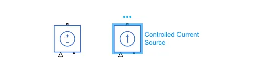
controlled current and voltage sources can be used in SIMULINK to represent different electrical loads or behaviors that the EV's powertrain and other systems may encounter in real-world driving scenarios.
Controlled current and voltage sources can be used to represent the electrical loads or behaviors of different components or subsystems of the EV in a larger system-level model, allowing for the analysis and integration of these components into the overall EV system.
Overall, controlled current and voltage sources are useful tools for evaluating and optimizing the performance and safety of the EV's electrical systems
controlled voltage and current sensor

controlled voltage and current sensors are used to measure the electrical properties of the EV's powertrain and other systems in SIMULINK. These sensors can be used to accurately and precisely measure the electrical characteristics of the EV's components and subsystems, such as voltage, current, power, and resistance.
Controlled voltage and current sensors can be used to measure the electrical characteristics of different components or subsystems of the EV in a larger system-level model, allowing for the analysis and integration of these components into the overall EV system.
Overall, controlled voltage and current sensors are useful tools for evaluating and optimizing the performance and safety of the EV's electrical systems in SIMULINK.
electrical reference

an electrical reference is a known and stable electrical quantity that is used as a reference point or standard for measuring or comparing other electrical quantities. Electrical references are commonly used in a variety of applications, including testing, measurement, and simulation, where it is important to have a consistent and accurate reference for electrical quantities.
solver configuration
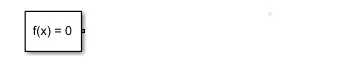
the solver configuration is an important consideration when simulating the performance and behavior of the EV's powertrain and other systems. The specific solver configuration options and settings will depend on the specific simulation needs and requirements of the EV model, as well as the characteristics of the model's equations and variables.
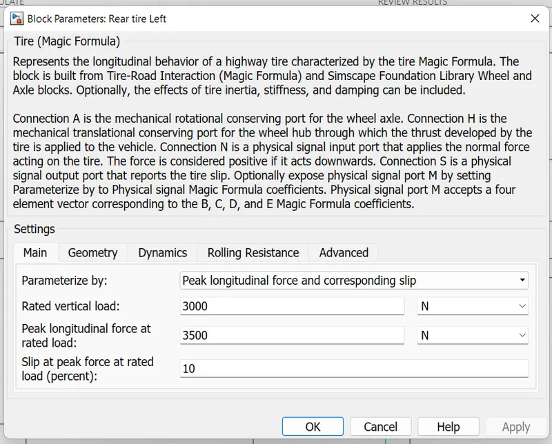
tire( magic formula )

The magic formula tire model is a mathematical model that represents the behavior and performance of a tire in terms of its lateral and longitudinal forces, as well as its slip angle and slip ratio. It is based on a combination of empirical data and physical principles, and is widely used due to its ability to accurately represent the complex behavior of tires under a wide range of operating conditions.
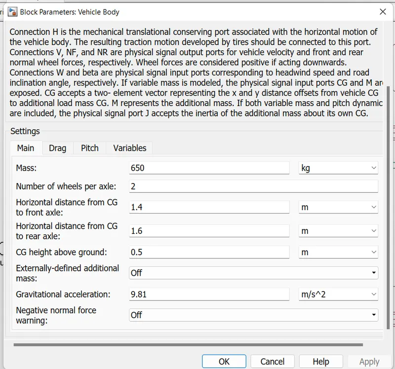
vehicle body
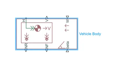
The vehicle body refers to the structural components of the EV that support the vehicle's weight and provide a platform for the other components and systems, such as the powertrain, suspension, and occupants. The vehicle body can also be a major contributor to the vehicle's overall aerodynamics and energy efficiency.
parameters
simple gear

A gear is a mechanical device that is used to transmit and modify torque and rotational speed between two or more rotating shafts. Gears are commonly used in a variety of applications, including electric vehicle (EV) design, where they are used to transmit power and torque from the EV's powertrain to the wheels.
VEHICLE DYMAMICS
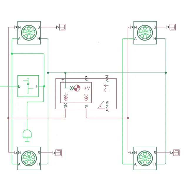
Vehicle dynamics refers to the behavior and performance of a vehicle as it moves and responds to different operating conditions, such as acceleration, braking, cornering, and road surface conditions. In SIMULINK, vehicle dynamics can be simulated and analyzed by modeling and connecting the different components and systems that affect the vehicle's motion, such as the vehicle body, tires, powertrain, and suspension.
To model and simulate vehicle dynamics in SIMULINK, the vehicle body and tires can be represented using a variety of block library elements, such as the Vehicle Body and Tire blocks. The specific configuration and parameters of these models will depend on the characteristics and design of the specific vehicle being simulated.
To connect the vehicle body and tires in SIMULINK, the lateral and longitudinal forces generated by the tires can be applied to the body through the suspension system, which translates these forces into motion of the body. The vehicle body model can then represent the motion and response of the vehicle to these forces, taking into account factors such as the vehicle's mass, center of gravity, and moment of inertia.
Overall, by modeling and connecting the vehicle body and tires in SIMULINK, it is possible to simulate and analyze the vehicle's dynamics under a wide range of operating conditions and scenarios, allowing for the evaluation and optimization of the vehicle's performance and handling.
result
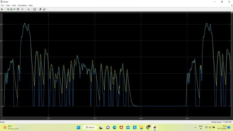
velocity output refering drive cycle source
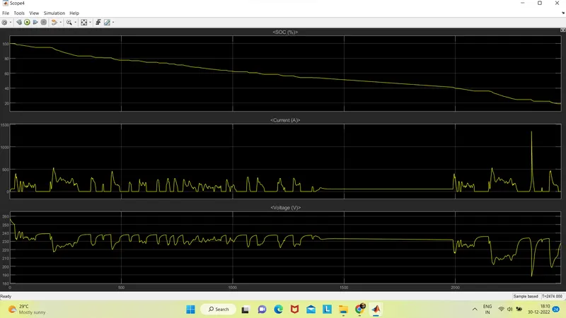
lithium ion battery outputs
current voltage and soc
explaination
- To use a PI controller in the longitudinal driver of a Simulink model, you would first need to determine the desired behavior of the system. This could include things like maintaining a constant speed, following a reference trajectory, or responding to external inputs.
-
Powertrain: This may include blocks such as the Electric Motor, Battery, and Gearbox blocks, which represent the EV's propulsion system and its components. These blocks may be connected to the Vehicle Body block to transmit the power and torque from the powertrain to the wheels.
-
Suspension: This may include blocks such as the Spring and Damper blocks, which represent the suspension components that connect the wheels to the vehicle body and absorb shock and vibration.
-
Electrical components: This may include blocks such as the Controlled Voltage and Current Source blocks, which represent the electrical loads and behaviors that the EV's electrical systems may encounter in real-world driving scenarios. These blocks may be connected to the EV's powertrain and other electrical components to evaluate their performance and behavior.
-
Sensors and measurement instruments: This may include blocks such as the Voltage and Current Sensor blocks, which represent the sensors and measurement instruments that are used to measure the electrical properties of the EV's components and systems. These blocks may be connected to the EV's powertrain and other components to evaluate their performance and behavior.
-
Electric Motor: The electric motor is the primary component that provides propulsion to the EV. It is powered by the battery pack and converts electrical energy into mechanical energy, which is then transmitted to the wheels through the gearbox and suspension system.
-
Battery: The battery pack stores the electrical energy that powers the electric motor and other electrical components of the EV. It is typically composed of a number of individual cells or modules, and may be represented in SIMULINK using a Battery block.
- lithium-ion battery in EV design using Simulink, you can use the "Battery" block from the Simscape Electrical library. This block allows you to specify parameters such as the battery's capacity, internal resistance, and initial state of charge. You can also specify the battery's discharge and charge curves, which describe how the battery's output voltage and current vary with its state of charge.
-
Gearbox: The gearbox is a mechanical device that is used to transmit and modify the torque and rotational speed between the electric motor and the wheels. It can be represented in SIMULINK using a Gearbox block, which allows for the simulation and analysis of the gearbox's performance and behavior.
-
Vehicle Body: The vehicle body is the structural component of the EV that supports the vehicle's weight and provides a platform for the other components and systems, such as the powertrain, suspension, and occupants. It can be represented in SIMULINK using a Vehicle Body block, which allows for the simulation and analysis of the vehicle's dynamics and performance.
conclusion
the Electric Motor, Battery, Gearbox, and Vehicle Body blocks, as well as other components and systems as needed. By modeling and simulating these components and systems in SIMULINK, it is possible to evaluate and optimize the performance and behavior of the EV under different operating conditions and scenarios. Overall, SIMULINK is a useful and valuable tool for EV design and analysis, allowing for the development and optimization of advanced and efficient EV systems.
It is important to note that proper modeling of a lithium-ion battery in EV design requires a detailed understanding of the battery's characteristics and behavior. Incorrectly modeling the battery can lead to inaccurate results and potentially unsafe designs.
To model the behavior of the EV as a whole, you may also need to include additional blocks in your Simulink model that represent other components of the EV system, such as the motor, power electronics, and sensors. You can then use these blocks to simulate the EV's performance under different operating conditions and analyze the results.
distance travelled = 4.94 km
we where able to provide result simular to reference and ther result were promising.