Project 1
To simulate the starting behavior of the 5 HP, 3-phase, 230V, 60Hz, 4-pole squirrel cage induction machine with the given parameters. However, before proceeding with the simulation, let's clarify the provided parameters:
- Stator resistance (r_s): 0.531 Ω
- Stator inductance (L_ls): 2.52 mH
- Rotor resistance (r_r): 0.408 Ω
- Magnetizing inductance (L_m): 84.7 mH
- Moment of inertia (J): 0.1 kgm^2
- Supply voltage (V_s): 230V, 60Hz
- Rated torque: T_rated (given)
- Load torque: 0.83 * T_rated
- Time to apply load: 0.7 seconds
- Time to remove load: 0.1 seconds
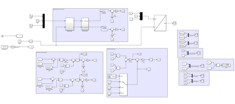
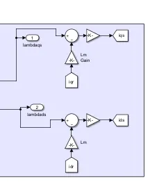
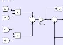
in the flux generator we have multiplied the stator resistance with stator current to get the voltage drop.
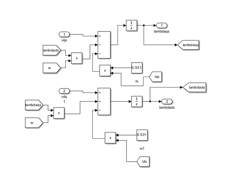
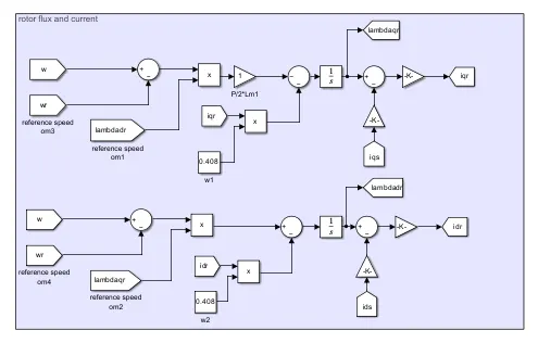
in the flux generator we have multiplied the rotor resistance with rotor current to get the voltage drop.
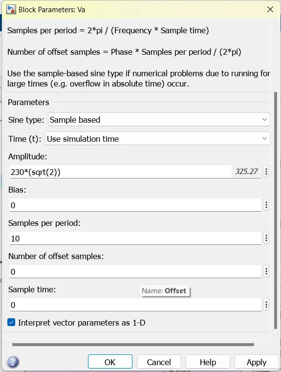
supply voltage : v rms = v/root(2)
Magnetizing inductance (L_m): 84.7 mH
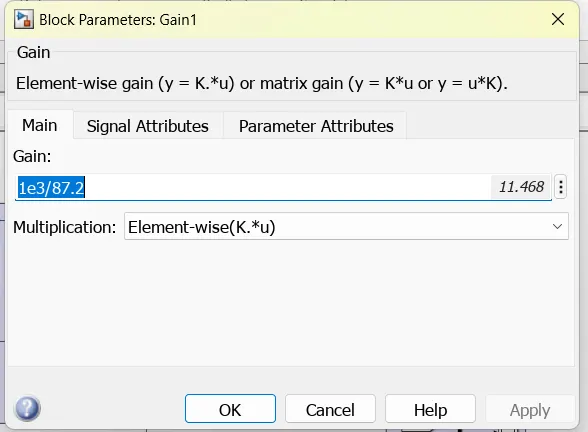
stator flux*mutal inductance = stator current
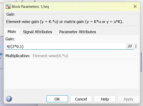
Moment of inertia (J): 0.1 kgm^2
after getting the torque genertaed we multiply torque with inertia of the rotor
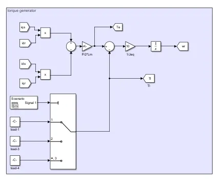
Rated torque: T_rated (given)
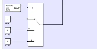
Load torque: 0.83 * T_rated
Time to apply load: 0.7 seconds
Time to remove load: 0.1 seconds
To simulate the starting behavior, we need to numerically solve the differential equations of the induction machine model. However, due to the complexity of the model and the non-linear behavior of the machine, the simulation process can be quite involved.
If you have access to simulation software like MATLAB/Simulink you can use them to model and simulate the induction machine behavior accurately.
Here's a general outline of the simulation process:
Simulating the start-up behavior of an induction motor in multiple reference frames is a complex task that requires a detailed mathematical model and numerical methods.
a) Simulate the start-up behavior of the induction motor represented in the stationary d-q reference frame. Provide simulation plots of v_qs(t), i_qs(t), i_ds(t), i_qr(t), i_dr(t), Te(t), Tl(t), and ωr(t).
In this reference frame, we will transform the equations of the motor to the d-q coordinates aligned with the stator flux. The equations will include the stator and rotor current components (i_ds, i_qs, i_dr, i_qr), stator voltage components (v_qs, v_ds), electromagnetic torque (Te), load torque (Tl), and rotor speed (ω_r).
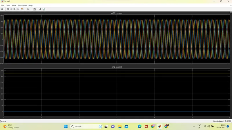
input current, ABC and DQ current.
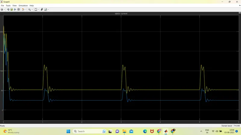
stator current
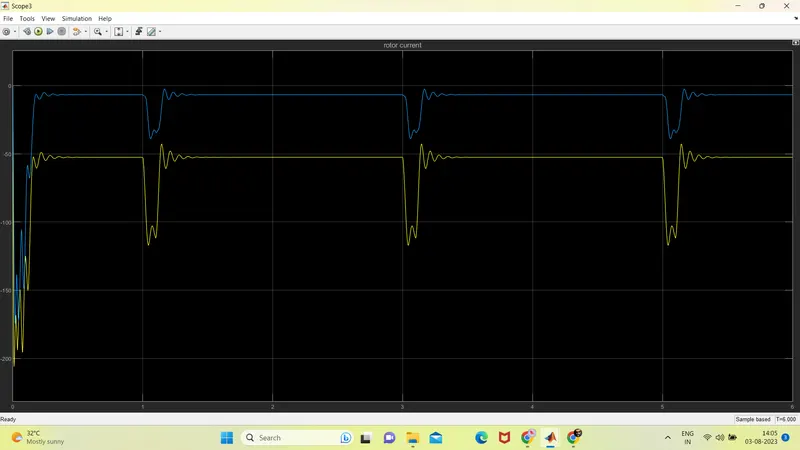
rotor current
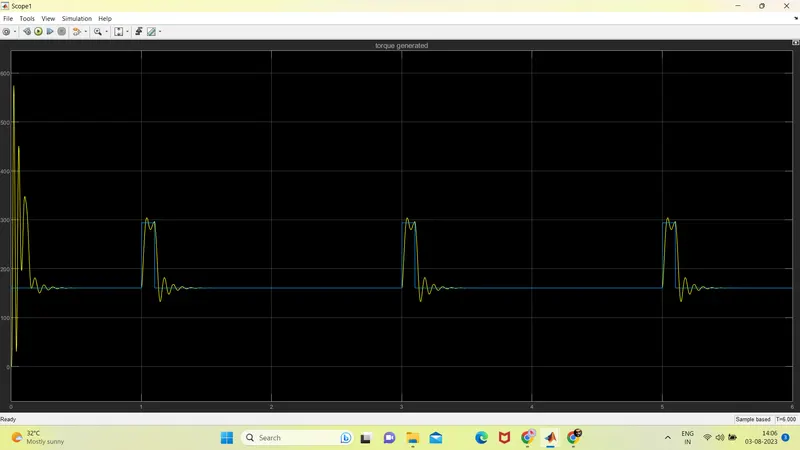
torque electric vs torque load
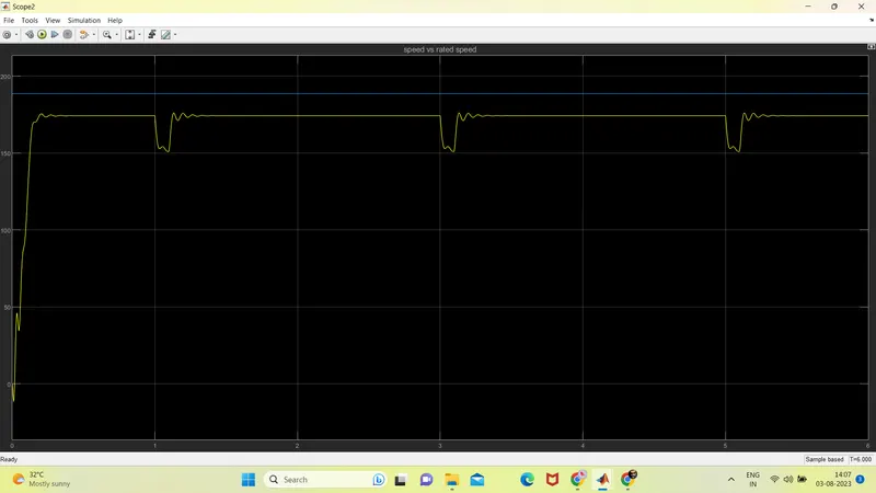
speed vs rated speed (Ns)

b) Simulate the start-up behavior of the induction motor represented in the synchronous reference frame. Provide simulation plots of v_eqs(t), i_eqs(t), i_eqr(t), Te(t), Tl(t), and ωr(t).
In this reference frame, we will align the d-q coordinates with the rotor flux. The equations will include the synchronous voltage components (v_eqs, v_dqs), stator current components (i_eqs, i_dr), electromagnetic torque (Te), load torque (Tl), and rotor speed (ω_r).
input current, ABC and DQ current.
stator current
rotor current
torque electric vs torque load
speed vs rated speed (Ns)
c) Simulate the start-up behavior of the induction motor represented in the rotor reference frame. Provide simulation plots of v_rqs(t), i_rqs(t), i_rqr(t), Te(t), Tl(t), and ωr(t).
In this reference frame, we will align the d-q coordinates with the rotor itself. The equations will include the rotor voltage components (v_rqs), rotor current components (i_rqs, i_rqr), electromagnetic torque (Te), load torque (Tl), and rotor speed (ω_r).
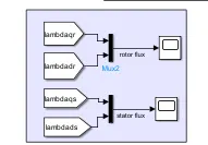
d) Simulate the start-up behavior of the induction motor represented in the rotor flux reference frame. Provide simulation plots of v_rfqs(t), i_rfqs(t), i_rfqr(t), Te(t), Tl(t), and ωr(t).
In this reference frame, we will align the d-q coordinates with the rotor flux. The equations will include the rotor flux voltage components (v_rfqs), rotor flux current components (i_rfqs, i_rfqr), electromagnetic torque (Te), load torque (Tl), and rotor speed (ω_r).
input current, ABC and DQ current.
stator current
rotor current
torque electric vs torque load
speed vs rated speed (Ns)
b) Simulate the start-up behavior of the induction motor represented in the synchronous reference frame. Provide simulation plots of v_eqs(t), i_eqs(t), i_eqr(t), Te(t), Tl(t), and ωr(t).
In this reference frame, we will align the d-q coordinates with the rotor flux. The equations will include the synchronous voltage components (v_eqs, v_dqs), stator current components (i_eqs, i_dr), electromagnetic torque (Te), load torque (Tl), and rotor speed (ω_r).
input current, ABC and DQ current.
stator current
rotor current
torque electric vs torque load
speed vs rated speed (Ns)
explaination :
To convert voltage from ABC (three-phase) representation to DQ (two-phase) representation for induction motor modeling, we use the Park's transformation, similar to what we did for the currents. The Park's transformation rotates the three-phase voltages from the ABC reference frame to the DQ reference frame, where the D-axis is aligned with the rotor flux and the Q-axis is perpendicular to it.
In the DQ reference frame, the D-axis represents the magnetic flux of the rotor, and the Q-axis represents the torque-producing component of the stator current. This transformation simplifies the control and modeling of the induction motor.
The transformation equations for voltage are as follows:
Park's Transformation (ABC to DQ):
v_d = v_a * cos(θ) + v_b * cos(θ - 2π/3) + v_c * cos(θ + 2π/3)
v_q = -v_a * sin(θ) - v_b * sin(θ - 2π/3) - v_c * sin(θ + 2π/3)
where v_d and v_q are the DQ-axis voltages, v_a, v_b, and v_c are the ABC-axis voltages, and θ is the electrical angle of the rotor.
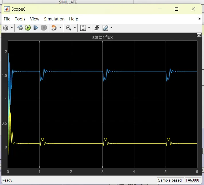
the stator flux
In mathematical terms, the stator flux components can be calculated as follows:
Ψ_d = ∫v_d dt
Ψ_q = ∫v_q dt
Where Ψ_d and Ψ_q are the DQ-axis components of the stator flux, and v_d and v_q are the DQ-axis voltages.
Integrating the DQ voltages over time provides you with the stator flux components
stator current
From Stator Flux to DQ Stator Current: Once you have obtained the stator flux components (Ψ_d and Ψ_q) from the stator voltage using the Inverse Park's transformation, you can obtain the stator current components (i_d and i_q) in the DQ reference frame by dividing the stator flux components by the stator winding inductances (L_d and L_q) as follows:
i_d = Ψ_d / L_d
i_q = Ψ_q / L_q
Where i_d and i_q are the DQ-axis stator current components, Ψ_d and Ψ_q are the DQ-axis stator flux components, and L_d and L_q are the stator winding inductances along the D and Q axes, respectively.
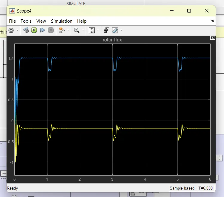
rotor flux
To obtain the rotor flux in the DQ reference frame (Ψ_d_r and Ψ_q_r) from the stator voltage and stator current, you can use the relationship between the stator and rotor flux in an induction motor. The rotor flux components can be estimated using the following equations:
DQ-axis Rotor Flux (Ψ_d_r and Ψ_q_r):
Ψ_d_r = (L_m * i_d - L_ls * i_d_r) / R_r
Ψ_q_r = (L_m * i_q - L_ls * i_q_r) / R_r
where Ψ_d_r and Ψ_q_r are the DQ-axis rotor flux components, i_d and i_q are the DQ-axis stator current components, i_d_r and i_q_r are the DQ-axis rotor current components, R_r is the rotor resistance, L_m is the magnetizing inductance, and L_ls is the stator leakage inductance.
The above equations are derived from the equations that relate
rotor current
To obtain the rotor current in the DQ reference frame (i_d_r and i_q_r) and the three-phase rotor current (i_a_r, i_b_r, and i_c_r) from the stator voltage and stator current information, you need to consider the relationship between the stator and rotor currents in an induction motor.
The relationship between the stator and rotor currents is given by the following equations:
DQ-axis Rotor Current (i_d_r and i_q_r):
i_d_r = i_d - (R_r / ω_r) * Ψ_q
i_q_r = i_q + (R_r / ω_r) * Ψ_d
Where i_d_r and i_q_r are the DQ-axis rotor current components, i_d and i_q are the DQ-axis stator current components, R_r is the rotor resistance, Ψ_d and Ψ_q are the DQ-axis stator flux components, and ω_r is the rotor speed in radians per second.
Electromagnetic torque
To obtain the electromagnetic torque in an induction motor, you can use the following formula based on the stator and rotor currents in the DQ reference frame:
Te = 1.5 * P * (Ψ_d * i_q - Ψ_q * i_d)
Where Te is the electromagnetic torque, P is the number of pole pairs in the motor, Ψ_d and Ψ_q are the DQ-axis components of the stator flux, i_d and i_q are the DQ-axis components of the stator current.
It's important to note that the electromagnetic torque is a function of the stator and rotor currents, as well as the stator flux. The formula above is valid for a 3-phase, 4-pole induction motor with sinusoidal winding distribution.
The electromagnetic torque represents the torque produced by the interaction of the stator magnetic field and the rotor magnetic field in an induction motor. It is the driving force that generates the mechanical output power of the motor.
speed
To obtain the speed of the torque, also known as the rotational speed or angular velocity of the motor, you can use the following relationship:
ω_r = Te / (P * K_t)
Where:
- ω_r is the rotational speed of the motor in radians per second.
- Te is the electromagnetic torque, which can be calculated using the formula provided in the previous response.
- P is the number of pole pairs in the motor.
- K_t is the torque constant of the motor.
The torque constant (K_t) is a motor parameter that relates the electromagnetic torque produced by the motor to the motor current. Its value depends on the motor design and can be obtained from the motor's datasheet or through experimentation.
Inverse Park's Transformation (DQ to ABC):
i_a = i_d * cos(θ) - i_q * sin(θ)
i_b = i_d * cos(θ - 2π/3) - i_q * sin(θ - 2π/3)
i_c = i_d * cos(θ + 2π/3) - i_q * sin(θ + 2π/3)
By using the Park's transformation for voltage, you can model and control the induction motor using DQ variables instead of ABC variables, making the control algorithms more straightforward and efficient.
CONCLUSION
In conclusion, modeling an induction motor involves understanding and implementing various transformations and equations to represent the motor's behavior accurately. Here's a summary of the steps involved in modeling an induction motor:
-
Motor Parameters: Start by gathering the necessary motor parameters, such as stator resistance, stator inductance, rotor resistance, magnetizing inductance, moment of inertia, etc.
-
Stator Current and Flux: Obtain the stator current and stator flux in the DQ reference frame using the Inverse Clarke's transformation and Inverse Park's transformation, respectively, from the stator voltage and current.
-
Rotor Current and Flux: Calculate the rotor current in the DQ reference frame using the relationship between the stator and rotor currents. The rotor flux in the DQ reference frame can be derived from the stator voltage and rotor current using the Inverse Park's transformation.
-
Electromagnetic Torque: Determine the electromagnetic torque using the stator current and stator flux components in the DQ reference frame.
-
Rotational Speed: Calculate the rotational speed of the motor using the electromagnetic torque and motor parameters.
-
Simulation: Utilize numerical integration techniques or simulation tools like MATLAB/Simulink or Python with appropriate libraries to simulate the start-up behavior of the motor and obtain simulation plots of various variables like voltages, currents, torques, and speed.