Project 1
Project 1
objective
1. Design a battery pack for a car roughly 150 Kw with 120 V. Use 3500 mAh 3.6V nominal NMC chemistry cell.
a. Design the battery pack configuration.
b. Draw the BMS topology for this battery pack.
answer :
To design a battery pack for a car with a power rating of 150 kW and a voltage of 120 V, you will need to determine the total energy capacity of the battery pack, as well as the number of cells and the configuration of the cells in the pack.
a. Design the battery pack configuration.
nominal voltage = 3.6 v
cell capacity = 3600 mAh
power =150 kWh
rated voltage =120 v
To find the number of cells in series, you will need to determine the desired voltage of the battery pack and the nominal voltage of the cells. The number of cells in series can then be calculated by dividing the desired voltage by the nominal voltage of the cells.
if the desired voltage of the battery pack is 120 V and the nominal voltage of the cells is 3.6 V, then the number of cells in series will be 120 V / 3.6 V = 33.33 cells.
we will round the cells in series as 33.33 cells to 34 cells
the nominal battery voltage is determind as
nominal battery voltage = rated battery voltage * nominal cell voltage = 34*3.6 v=122.4v
To find the number of cells in parallel, you will need to determine the desired current capacity of the battery pack and the capacity of a single cell. The number of cells in parallel can then be calculated by dividing the desired current capacity by the capacity of a single cell.
battery current = total power / rated voltage = 150 kWh / 120 v =1250A
For example, if the current capacity of the battery pack is 120 A and the capacity of a single cell is 3500 mAh, then the number of cells in parallel will be 1250 A / (3500 mAh / 1000) = 357.14 cells. You will need to round this number up to the nearest whole number (86 cells) to determine the actual number of cells in parallel.
Keep in mind that the capacity of a single cell is typically measured in milliampere-hours (mAh), so you may need to convert it to amperes (A) before performing the calculation. To do this, divide the capacity in mAh by 1000.
we will round the cells in parallel as 357.14 cells to 358 cells
the Design the battery pack configuration will be 344 cells in sereis and 358 cells in parallel
Design the battery pack configuration : 34s358p
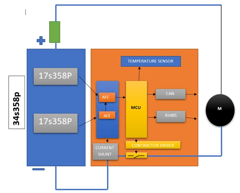
b. Draw the BMS topology for this battery pack.
===========================================================================
A battery management system (BMS) is a system that monitors, manages, and protects a battery or a group of batteries. It is typically used in battery-powered applications, such as electric vehicles (EVs), hybrid electric vehicles (HEVs), grid storage systems, and portable electronic devices.
The architecture of a BMS typically includes the following components:
-
Sensors: These are used to measure various parameters of the battery, such as the voltage, current, temperature, and state of charge (SOC).
-
Control unit: This is the central processing unit of the BMS, which receives input from the sensors and makes decisions based on the data it receives. It is responsible for controlling the charging and discharging of the battery, as well as protecting the battery from overcharge, overdischarge, and other types of damage.
-
Actuators: These are used to control the flow of charge into and out of the battery. Examples of actuators include relays, switches, and transistors.
-
Communication interface: This is used to connect the BMS to other systems, such as the vehicle's onboard computer or a remote monitoring system. It may use a variety of communication protocols, such as CAN bus, RS-232, or Ethernet.
-
Power supply: This is used to power the BMS itself, as well as any associated sensors, control units, and actuators. It may be a separate power source or it may be derived from the battery itself.
main components expination in BMS
AFE
AFE stands for "analog front-end." In the context of a battery management system (BMS), an AFE is a circuit that is used to interface the BMS with the battery. It is responsible for converting the analog signals from the battery into digital signals that can be processed by the BMS control unit.
An AFE typically includes the following components:
-
Amplifiers: These are used to amplify the low-level analog signals from the battery, such as the voltage and current, to a level that can be accurately measured and processed by the BMS.
-
Analog-to-digital converters (ADCs): These are used to convert the amplified analog signals into digital signals that can be processed by the BMS control unit.
-
Filters: These are used to remove noise and other unwanted signals from the analog signals, in order to improve the accuracy and reliability of the measurements.
-
Isolation: The AFE may also include isolation circuits, which are used to electrically isolate the BMS from the battery. This is important in order to protect the BMS from any voltage spikes or other electrical hazards that may be present in the battery.
MCU
In a battery management system (BMS), the microcontroller unit (MCU) is the central processing unit that controls the operation of the BMS. It is responsible for executing the algorithms that are used to monitor, manage, and protect the battery or group of batteries.
The MCU is typically a programmable device that can be programmed with the specific algorithms and logic required for the particular application. It receives input from the sensors in the BMS and makes decisions based on this input. It may also control the actuators in the BMS, such as relays or switches, in order to control the flow of charge into and out of the battery.
The MCU may also be connected to a communication interface, such as a CAN bus or RS-232 port, in order to exchange data with other systems, such as the vehicle's onboard computer or a remote monitoring system.
current shunt meaaurment
A shunt is a device that is used to measure the current flow in a circuit. In a battery management system (BMS), a shunt is typically used to measure the current flowing into and out of the battery.
A shunt is placed in parallel with the load (e.g., the battery) and has a very low resistance, typically in the milliohm range. When current flows through the shunt, a voltage drop is produced across the shunt that is proportional to the current flowing through it. By measuring this voltage drop, it is possible to determine the current flowing through the shunt.
The shunt may be connected to a current sensor, such as a hall effect sensor or a resistive sensor, which converts the voltage drop across the shunt into a usable electrical signal that can be processed by the BMS control unit.
Shunts are often used in BMSs because they are accurate and can handle large current flows. They are also relatively inexpensive and easy to implement.
contractor driver switch
A MOSFET switch is controlled by the voltage applied to its gate terminal, and it can be used to switch current on and off in a circuit.
a MOSFET switch could be used as part of a circuit that controls the flow of charge into or out of a battery. For example, a MOSFET switch could be used to connect a battery charger to the battery when it is being charged, or to disconnect the battery from the charger when it is fully charged.
========================================================================================
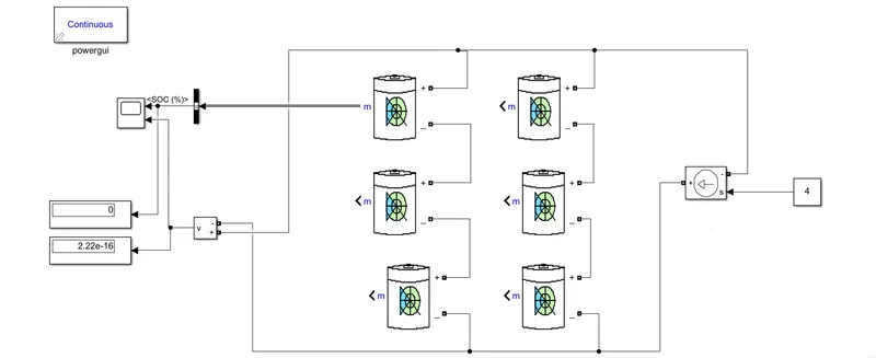
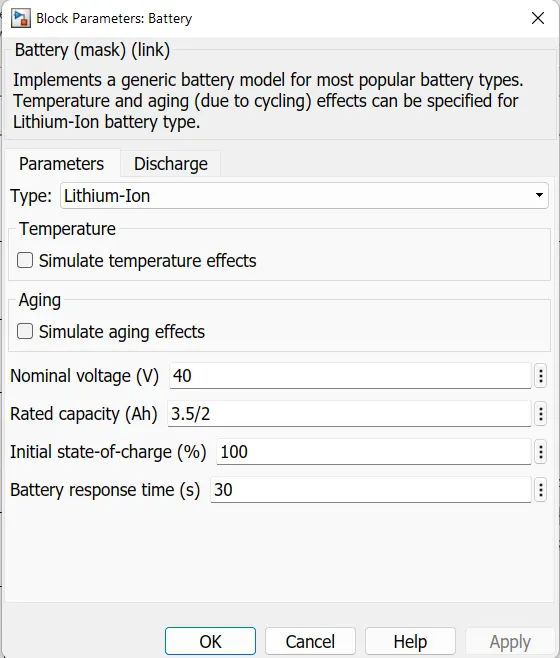
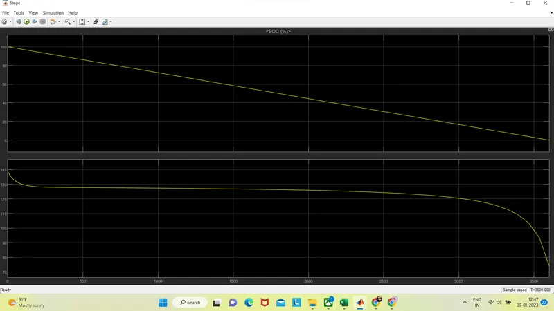
2. Build a 3S2P battery pack configuration with generic battery block using Matlab/Simulink.
answer :
===========================================================================
CONCUSION
the objective of the projec tis met and completed , here the Design a battery pack for a car roughly 150 Kw with 120 V. Use 3500 mAh 3.6V nominal NMC chemistry cell. Designed the battery pack configuration. Drawed the BMS topology for this battery pack. abd builted Build a 3S2P battery pack configuration with generic battery block using Matlab/Simulink. andd obtained the output