Project 2
AIM & INTRODUCTION- Model a PEB Warehouse & Design using STAAD. Pro with following given data
|
BUILDING INPUT |
||
|
Length |
630 (inside sheet to C/L of column) + (2 X 8045 + (19 X 8000) of columns) + 630 (C/L of column to inside of sheeting) = 169350 mm inside to inside sheeting. |
|
|
Width |
630 (inside sheet to C/L of column) + (8905 + 8000 + ( 5 X 7200) +6585 c/c of columns) + 630 (C/L of column to inside of sheeting) = 59450 mm inside to inside sheeting. |
|
|
Height |
Clear height from FFL to Bottom of rafter at eaves shall be 9200 mm |
|
|
Bottom level of base plate for all PEB columns shall be 250mm below from FFL |
||
|
Roof slope |
1:20 OR as suggested by PEB vendor but not less than 1:20 |
|
|
Internal column spacing |
Internal column shall be provided 16.00 m c/c length wise. Jack beam shall be provided to compensate for eliminated column. |
|
CANOPY |
||
|
Canopy 1 |
Between grid 4 to 7 and on grid A |
|
|
Length |
3 * 8000 = 24000 MM c/c of canopy rafter. |
|
|
Width |
Center line of PEB column to outside of canopy shall be 5250 mm. |
|
|
Clear Height |
Clear height from bottom of steel of canopy to Finish floor level shall be 3900 mm. |
|
|
Roof slope |
1:20 - Slope as shown in architectural drawing - Canopy sloping towards building - Valley gutter to be provided. |
|
|
Canopy 2 |
Between grid 16 to 19 and on grid A |
|
|
Length |
3 * 8000 = 24000 MM c/c of canopy rafter. |
|
|
Width |
Center line of PEB column to outside of canopy shall be 5250 mm. |
|
|
Clear Height |
Clear height from bottom of steel of canopy to Finish floor level shall be 3900 mm. |
|
|
Roof slope |
1:20 - Slope as shown in architectural drawing - Canopy sloping towards building - Valley gutter to be provided. |
|
MEZZANINE FLOORS |
||
|
Mezzanine - 1 |
Between grid 1 to 3 and grid A to C |
|
|
Columns for mezzanine |
Mezzanine columns shall be provided only on grid lines B2, B3, C2 & C3 |
|
|
These extra mezzanine columns on grid B3, C2 & C3 shall extend up to rafter level, however, these columns shall not be treated as support for rafter. |
||
|
Mezzanine columns on grid B2 shall not extend above mezzanine floor. |
||
|
Clear height below mezzanine |
Clear height from bottom of rafter at knee to top of RCC slab of mezzanine floor shall be 5.000m |
|
|
Clear height from top of RCC slab of mezzanine floor to FFL shall be 4.200m |
||
|
Clear height from bottom of steel of mezzanine beam to top of RCC grade slab shall be 3.000m minimum. |
||
|
Extent of Mezzanine floor |
Mezzanine floor shall extend up to inside of sheeting on peripheral and on remaining sides Mezzanine floor shall be provided up to outside flange of columns. |
|
|
Mezzanine - 2 (Future) |
Between grid 20 to 22 and grid A to C |
|
|
Columns for mezzanine |
Mezzanine columns shall be provided only on grid lines B20, B21, C20 & C21 |
|
|
These extra mezzanine columns on grid 20B, 21C & 20C shall extend up to rafter level, however, these columns shall not be treated as support for rafter. |
||
|
Mezzanine columns on grid 21B shall not extend above mezzanine floor. |
||
|
Clear height below mezzanine |
Clear height from bottom of rafter at knee to top of RCC slab of mezzanine floor shall be 5.000m |
|
|
Clear height from top of RCC slab of mezzanine floor to FFL shall be 4.200m |
||
|
Clear height from bottom of steel of mezzanine beam to top of RCC grade slab shall be 3.000m minimum. |
||
|
Extent of Mezzanine floor |
Mezzanine floor shall extend up to inside of sheeting on peripheral and on remaining sides Mezzanine floor shall be provided up to outside flange of columns. |
|
OADS |
||
|
Dead Load (DL) |
||
|
|
Self weight of structure including all structural members & fasteners + Approx. 10 Kg / M2 for purlins and 15 KG / M2 for portal. |
|
|
|
Self weight of 150 thk. RCC slab + self weight of structural members shall be considered on mezzanine floors. |
|
|
|
Loss of 230 thk. Brick wall - 4m high shall be considered on entire periphery of mezzanine. |
|
|
|
Floor finish / Waterproofing loads of 150 Kg / M2 shall be considered on mezzanine floors. |
|
|
|
Additional Load of 500 Kg/m2 shall be considered on mezzanine floors. |
|
|
|
||
|
Live Load (LL) |
||
|
|
On roof and on canopy - 57 Kg. / M2 |
|
|
|
On Mezzanine floor 1 & 2, as defined above - 400 Kg/ M2 |
|
|
|
In sunk slab area (Toilet area - as marked in architectural drawings) -Live Load of 200 Kg. / m2 to be considered. |
|
Wind Load (WL) |
||
|
|
As per IS : 875 - Part 3 - 2015 |
|
|
|
Basic Wind speed - 39 m / sec. |
|
|
|
K1 - 1.00 |
|
|
|
K2 - 1.05 (Terrani Catogory-1. Building height at eaves = 10.50 m) |
|
|
|
K3 - 1.00 |
|
|
|
K4 - 1.00 (For other structures) |
|
|
|
Coefficient of cyclonic wind may be taken as 1, since site is located more than 60 Km away from Coast) |
|
|
|
Kd -0.9 |
|
|
|
Ka(Rafter) - 0.8 or as per tributary area. |
|
|
|
Ka(Column) - 0.8245 or as per tributary area. |
|
|
|
Ka(Purlin) - 0.9721 or as per tributary area. |
|
|
|
Ka(Side Runner) - 0.978 or as per tributary area |
|
|
|
Kc -0.9 |
|
|
|
Cpe - As per table 5 & 6 of IS: 875 (Part 3) - 2015 |
|
|
|
Cpi - 0.2 |
|
|
|
Consider load cases with internal pressure (Cpi +ve) and internal suction (Cpi -ve) |
|
|
Purlins / Side runners must be designed for local co-efficient as given in IS: 875 (Part 3) 2015, Table 5 & 6 |
||
|
Solid partition shall be designed for only internal wind pressure i.e., only cpi. |
||
|
Seismic Load (SL) |
||
|
|
As per IS: 1893 - 2016 |
|
|
|
Seismic zone - III - Z = 0.16 |
|
|
|
Rf - 4.0 |
|
|
|
I - 1.0 |
|
|
|
SS - 3.0 |
|
|
|
25% of Live Load on roof shall be considered for calculation of seismic forces. |
|
|
|
100% of collateral load on roof shall be considered for calculation of seismic forces. |
|
|
|
50% of (Live load + Collateral load) on mezzanine floor shall be considered for calculation of seismic forces. |
|
|
|
100% of Dead load shall be considered for calculation of seismic forces. |
|
|
|
For seismic in longitudinal direction, diaphragm action due to purlin and sheeting can be considered. Diaphragm actions should not be used while designing bracing system for wind load. |
|
|
|
Provisions of Chapter 12 of IS: 800 - 2007 need not be considered while designing structure. |
|
|
|
||
|
LOAD COMBINATION |
||
|
For Strength (Limit State design) |
1.5 DL + 1.5 LL + 1.5 CL |
|
|
1.5 DL + 1.5 WL (No increase in permissible stresses) |
||
|
0.9 DL + 1.5 WL (No increase in permissible stresses) |
||
|
1.2 DL + 1.2 LL + 1.2 CL + 1.2 WL (Loads reduced. No increase in permissible stresses) |
||
|
1.5 DL + 1.5 SL (No increase in permissible stresses) |
||
|
0.9 DL + 1.5 WL (No increase in permissible stresses) |
||
|
1.2 DL + 1.2 LL + 1.2 CL + 1.2 SL (Loads reduced. No increase in permissible stresses) |
||
|
Any other load combination that may be found necessary for design. |
||
|
For Strength (Working stress design) |
1.0 DL + 1.0 LL + 1.0 CL |
|
|
1.0 DL + 1.0 WL (No increase in permissible stresses) |
||
|
0.6 DL + 1.0 WL (No increase in permissible stresses) |
||
|
1.0 DL + 0.8 LL + 0.8 CL + 0.8 WL |
||
|
1.0 DL + 1.0 SL (No increase in permissible stresses) |
||
|
0.6 DL + 1.0 SL (No increase in permissible stresses) |
||
|
1.0 DL + 0.8 LL + 0.8 CL + 0.8 SL |
||
|
Any other load combination that may be found necessary for design. |
||
|
For Serviceability |
1.0 DL + 1.0 LL + 1.0 CL |
|
|
1.0 DL + 1.0 WL (No increase in permissible stresses) |
||
|
0.6 DL + 1.0 WL (No increase in permissible stresses) |
||
|
1.0 DL + 0.8 LL + 0.8 CL + 0.8 WL |
||
|
1.0 DL + 1.0 SL (No increase in permissible stresses) |
||
|
0.6 DL + 1.0 SL (No increase in permissible stresses) |
||
|
1.0 DL + 0.8 LL + 0.8 CL + 0.8 SL |
||
|
Any other load combination that may be found necessary for design. |
||
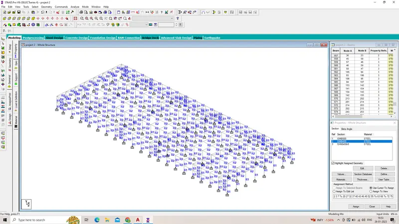
Length= 158m
Width = 60m
First & Last Bay along length = 9m
First & Last Bay along width = 6m
Height = 9m
Various component of structure are- Rafter, Tie Beam, Jack Beam, Horizontal & Vertical Bracing, Columns etc.
Member properties and fixed supports are assigned to each and every member of the structure.
SEISMIC LOAD-
|
Seismic zone - III - Z = 0.16 |
|
Rf - 4.0 |
|
I - 1.0 |
|
SS - 3.0 |
|
25% of Live Load on roof shall be considered for calculation of seismic forces. |
|
100% of collateral load on roof shall be considered for calculation of seismic forces. |
|
50% of (Live load + Collateral load) on mezzanine floor shall be considered for calculation of seismic forces. |
|
100% of Dead load shall be considered for calculation of seismic forces. |
|
For seismic in longitudinal direction, diaphragm action due to purlin and sheeting can be considered. Diaphragm actions should not be used while designing bracing system for wind load. |
DEAD LOAD - SELFWEIGHT ASSIGNED TO THE FRAME
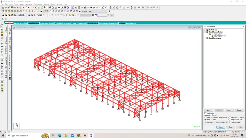
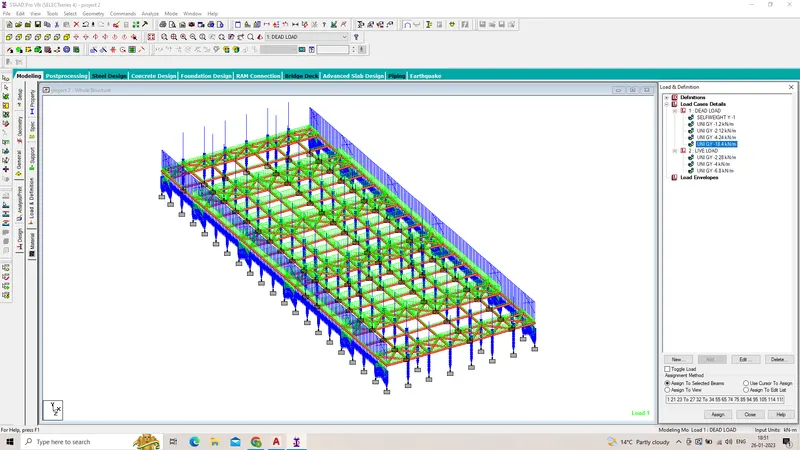
Additional load due to Purlin- 10 Kg/`m^2`and 10 kg/`m^2`for roof sheeting are as per calculation and print screen given below-
= 20x 6 ( Bay width along span of truss) = 120 Kg/`m^2`
=1.2 KN/m^2
Colateral Load- 2.12 KN/m on End Rafter & 4.24 KN/m on Intermediate Rafter
Live Load on Main frame- 2.28 KN.m
DEAD LOAD ON MEZANNINE FLOOR- LOAD DUE TO 230 MM THICK AND 4 M HEIGHT WALL AROUND THE PERIPHERY OF MEZANNINE FLOOR
20X 0.23X4 =18.4 KKN/M ( ON BOTH MEZANNINE FLOOR)
LIVE LOAD ON MEZANNINE FLOOR- 4 KN/ sqm or MEMBER LOAD= 6.8 KN/m on all secondary beams except end beams where load will be 3.4 KN/n ( 4 KN/sqmx 1.78 m (spacing of secondary beams)
Wind load -
SEISMIC LOAD AS PER- IS: 1893: 2002 AND AS PER FOLLWING PARAMETERS
SEISMIC ZONE 3 SO , Z=0.16
RF-5
IMPORTANCE FACTOR I= 1 ( FOR GENERAL BUILDING)
SS=1
ST ( SOIL TYPE) =1 FOR MEDIUM & DENSE SOIL
DM= 0.05
Basic wind speed = 39 m/s
K1=1 , K2= 1.05 ( Terrain category), K3=1 , K4 ==1 ( Cyclonic zone)
Design wind peed Vz= VbxK1xK2xK3xK4
= 39x1x1.05x1x1= 40.95 m/s
Wind Pressure Pz = 0.6 x`V_z^2` = 0.6x `(40.95)^2` =1006.142 N/`m^2`
Ka= 0.8245 ( for column)
Ka=0.8 ( for rafter)
Kd=0.9
Kc=0.9
KaxKdxKc = 0.8245x0.9x0.9 = 0.68 < 0.7 so taking least value as 0.72
Design Pressure Pd = PzxKaxKdxKc = 1.006142x0.7 = 704.3 N/`m^2` = 0.704 KN/m^2
Cpi = +/- 0.2
h/w = 10.05/60 = 0.1675
l/w = 170/60 = 2.833
External pressure coefficient for walls for rectangular clad building From Table 5 of IS 875 ( part 3) for h/w < 1/2 and 3/2 < l/w <4
| Wind Angle | C_(pe) | C(pe) | C_(pe) | C_(pe) |
| Wall A | Wall B | Wall C | Wall D | |
| `0^0` | + 0.7 | - 0.25 | - 0.6 | - 0.6 |
| 90^0 | -0.5 | -0.5 | +0.7 | -0.1 |
External pressure coefficient for PITCHED ROOF of rectangular clad building From Table of IS 875 ( part 3) for h/w < 1/2
`
| Roof angle | wind angle `0^0` | wind angle `0^0` | wind angle `90^0` | wind angle `90^0` |
| EF | GH | EG | FH | |
| -0.86 | -0.4 | -0.8 | -0.4 |
On Canopy-
Roof angle= 2.86 degree
Cp( -ve) = -1.08 ( Uplift)
Cp (+ve) = + 0.35
Force on Canopy = -1.08x0.704x8 = 6.08 KN/m ( upward)
Force on Canopy = +0.35x0.704x8 = 1.97 KN/m (downward)
For `theta =0^0`and `C_(p i)=+0.2`, `P_d =0.704 KN//m^2`
| Surface | `C_(pe)` | C_(pi) |
`C_p= C_(pe)-C_(p i)` |
Wind force on frame `F=C_pxxAxxP_d` |
| A | +0.7 | 0.2 | 0.5 | 1.41/2.82 |
| B | -0.25 | 0.2 | -0.45 | 1.27/2.54 |
| C | -0.6 | 0.2 | -0.8 | -1.7/-3.4 |
| D | -0.6 | 0.2 | -0.8 | -1.7/-3.4 |
| EF | -0.86 | 0.2 | -1.06 | -2.52//-5.04 |
| GH | -0.4 | 0.2 | -0.6 | -1.43/-2.85 |
| EG | -0.8 | 0.2 | -1.0 | -4.75 |
For `theta =0^0`and `C_(p i)=-0.2` `P_d =0.704 KN//m^2`
| Surface | `C_(pe)` | C_(pi) | `C_p= C_(pe)-C_(p i)` | Wind force on Gabian/Main frame |
| A | +0.7 | -0.2 | 0.9 | 2.53/5.07 |
| B | -0.25 | -0.2 | -0.05 | -0.14/-0.28 |
| C | -0.6 | -0.2 | -0.4 | -0.85 /-1.69 |
| D | -0.6 | -0.2 | -0.4 | -0.85 /-1.69 |
| EF | -0.86 | -0.2 | -0.66 | -1.57/-3.13 |
| GH | -0.4 | -0.2 | -0.2 | -0.48/-0.95 |
| EG | -0.8 | -0.2 | -0.6 | -1.43 |
For `theta =90^0`and `C_(p i)=+0.2`, `P_d =0.704 KN//m^2`
| Surface | `C_(pe)` | C_(pi) | `C_p= C_(pe)-C_(p i)` | Wind force on frame |
| A | -0.5 | +0.2 | -0.7 | -1.97/-3.94 |
| B | -0.5 | +0.2 | -0.7 | -1.97/-3.94 |
| C | +0.7 | +0.2 | 0.5 | 1.06/2.11 |
| D | -0.1 | +0.2 | -0.3 | -0.71/-1.43 |
| EG | +0.8 | +0.2 | +0.6 | 1.43/2.85 |
| EG | +0.8 | +0.2 | +0.6 | 1.43/2.85 |
For `theta =90^0`and `C_(p i)=-0.2`, `P_d =0.704 KN//m^2`
| Surface | `C_(pe)` | C_(pi) | `C_p= C_(pe)-C_(p i)` | Wind force on frame |
| A | -0.5 | -0.2 | -0.3 | -0.85/-1.69 |
| B | -0.5 | -0.2 | -0.3 | -0.85/-1.69 |
| C | +0.7 | -0.2 | 0.9 | 2.14/4.28 |
| D | -0.1 | -0.2 | 0.1 | -0.24/-0.48 |
| EG | +0.8 | -0.2 | +1.0 | 2.38/4.75 |
| EG | +0.8 | -0.2 | +1.0 | 2.38/4.75 |
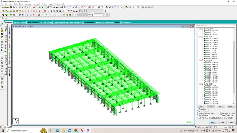
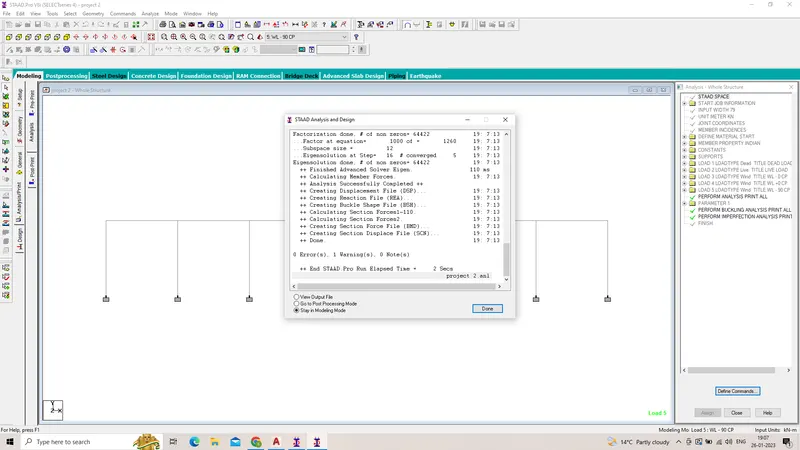
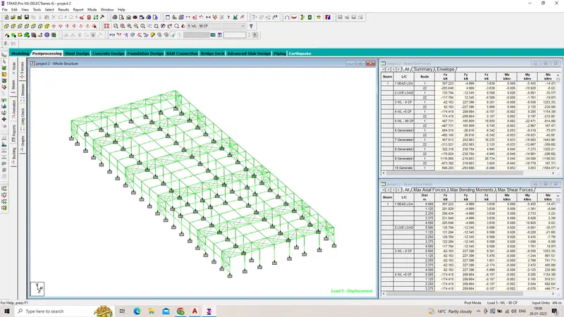
ALL PARAMETERS ASSIGNED AND FRAME IS SUCCESSFULLY ANALYSED WITH ZERO ERRORS
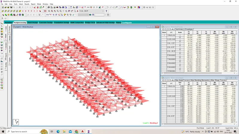
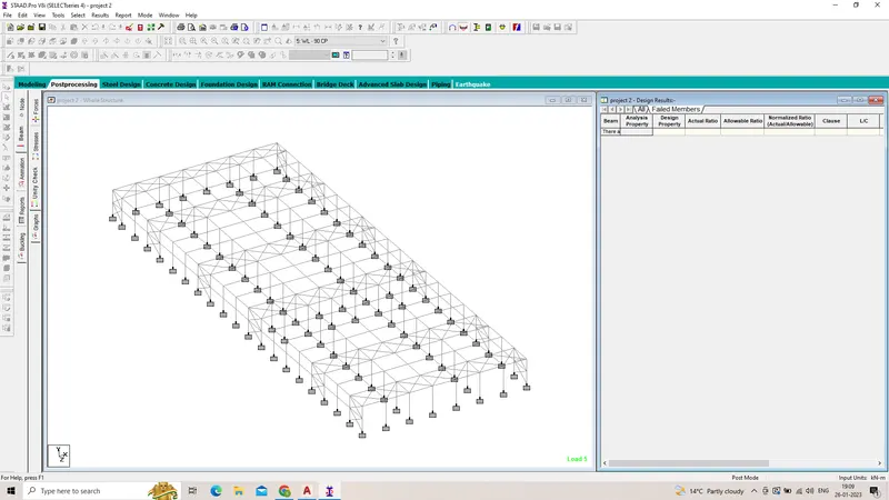
NO FAILED MEMBERS
STADD FILE ATTACHED BEOW FOR REFERENCE
1) STAAD Model of Industrial Ware House with given length, width and height is prepared including arrangement of canopies and Mezzanine floor and arrangement of interiors and exteriors columns as attached.
2) Suitable member property to various components of ware house such as Rafter, Tie Beam,Jack Beab,Collumn, Vertical & Horizontal racing etc. have been assigned.
3) Dead Load, Live Load, Colateral Load, Wind Load and Seismic Load have been assigned as per given input. Load combination for strength case and Serviceability case have been formed and included in the design.
4) Design Patrametes such as Check Code, Ratio, Beam, Yield Strength, Main, STP, LX,LY,LZ,KX,KY,KZ Steel take off have been assigned to the required members.
On performing Analysis command , No Error or Notice has been Reported. Design is checked for strength and serviceability case and found safe.
Value of utilization ratio is with permissible value of 1 for all members.