Project 2_Design & Analysis of a Hostel building at Guwahati, Assam
The architectural drawings of a G+3 RCC building is provided to us. Hostel block in an academic institute in Guwahati, Assam
The walls are made of AAC blocks , density = 6kN/m^3.
The buildings rests on type 3 soil. The ground floor level is at a height of 2 meters above the existing site level.
Grade of concrete M25
Longitudinal reinforcement - Fe500
Shear reinforcement - Fe415
Piles of length 10 meters and 500 mm diameter with a load-carrying capacity of 280 KN is to be used.
> We have to calculate and assume necessary data from the given architectural and site information.
> Model , analyse and design the frame structure in ETABS software.
> Model , analyse and design the frame structure in SAFE software.
> To produce structural typical floor plan and typical rebar drawings.
Following are the assummptions taken to model and analyse the structure in the intial phase.
> Pinned support , base + 5 story (plinth to roof ) + 1 mumty
>Column 550 x 650
>Beam 450 x 550
>Slab thickness 150mm
> No shear walls are provided as not necessary
>Seismic zone - V
> Floor live load 2kN/m^2
>Terrace live load 1kN/m^2
>Floor Finish + Ceiling Finish 1kN/m^2
>Partition wall load 3.5kN/m
>Balcony wall load 1kN/m
IS CODE PROVISIONS TAKEN INTO ACCOUNT FOR REFERENCE ARE :
- IS 875 part 1
- IS 875 part 2
- IS 13920
- IS 1893
- IS 2911 part 2
- IS 456
- SP 34
Point spring of each pile= area of pile x young's modulus / length of pile = 196349 x 25000/ 10000 = 490872.5 kN/m
Rebar yield strength Fy = 500 N/mm^2
Rebar ultimate strength Fu = 575 N/mm^2
Elastic modulus = 25000N/mm^2
Number of piles required = unfactored load with self weight addition / individual pile capacity , for symmetry we take even no. of piles in every footing.
Taking centre to centre distance between piles = 2.5 x pile dia = 1250mm
Edge distance from pile center = 1 x pile diameter = 500mm
Assumed pile cap depth = 500mm
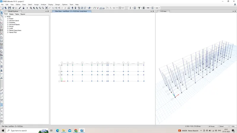
The basic model in Etabs is designed
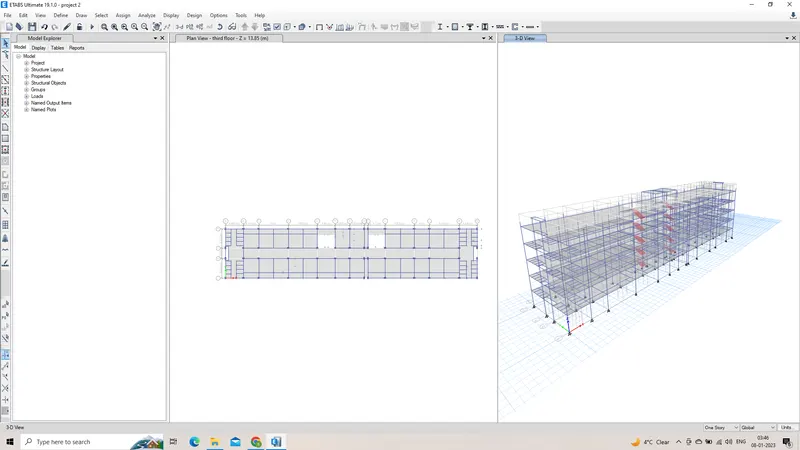
Every structural member is assigned to the model and ready to be checked.
No warning messages encountered , therefore model can be analysed further.
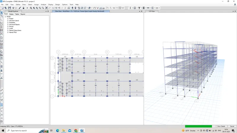
Assumed and provisional loads are assigned to the structure for analysis
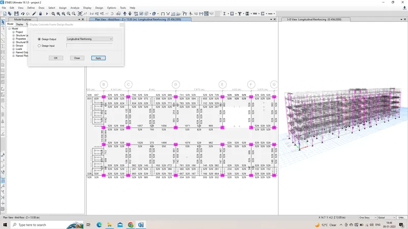
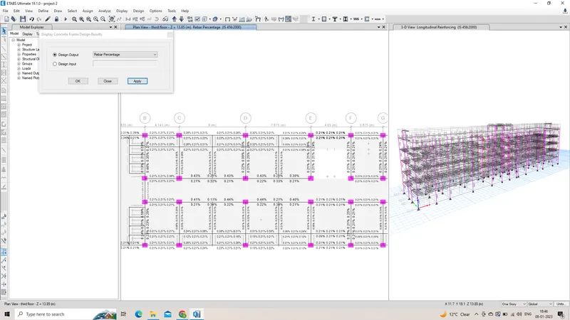
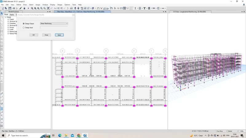
Checking the longitudinal reinforcement, shear reinforcement, rebar percentage
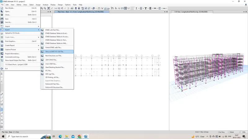
The base story is then exported to SAFE SOFTWARE with all the reaction forces
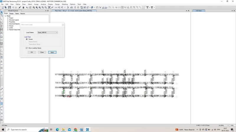
The DEAD ABOVE stresses are checked first
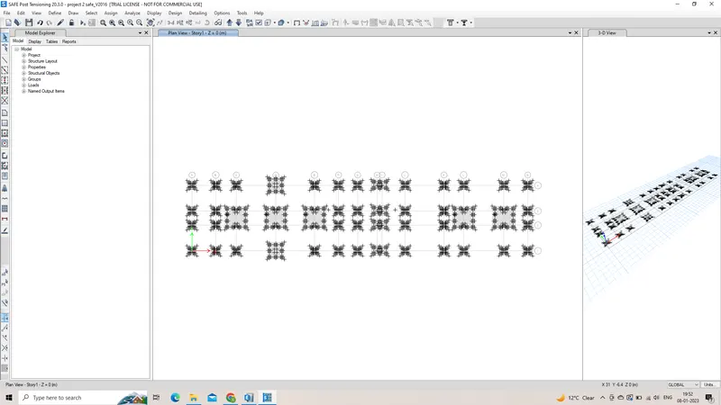
The footing is then designed with appropriate number of piles to every column in the grids.
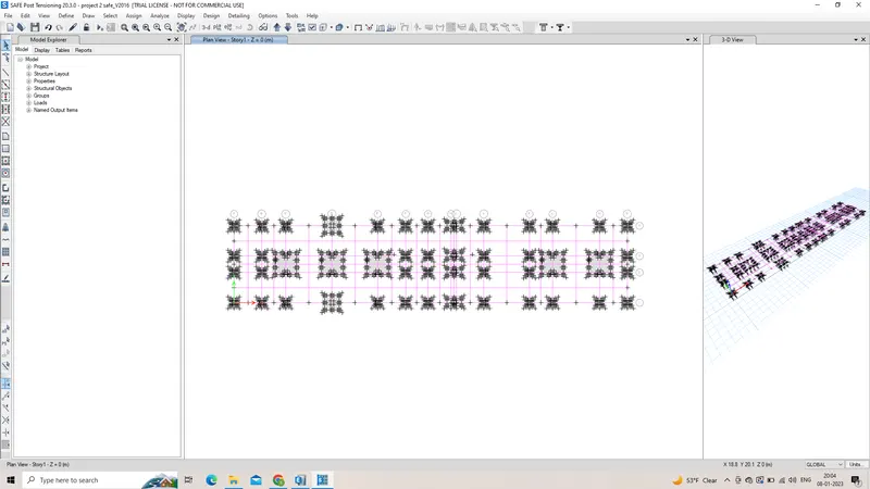
Adding the design strips to the structure.
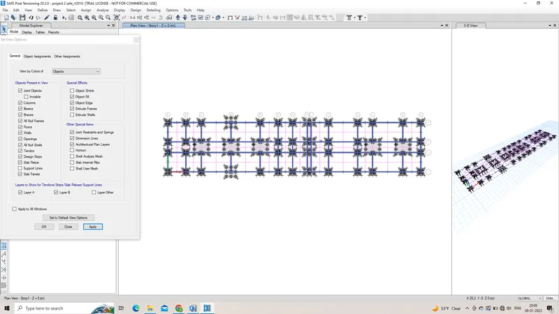
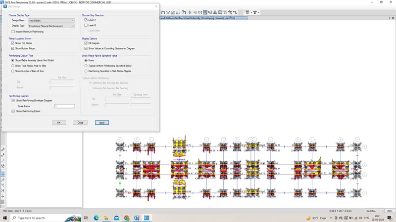
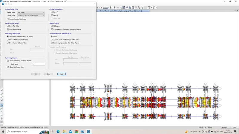
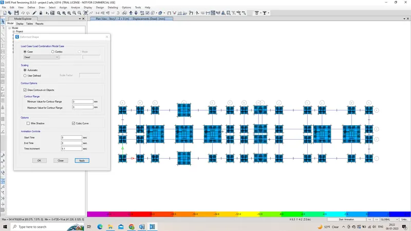
Deformations are only about 2mm which is acceptable
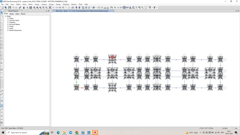
Punching shear or also known as two way shear , is less then 1 , therefore no failure of structure , hence check passed.

Given above is a typical column detail of size : 550 x 650 mm
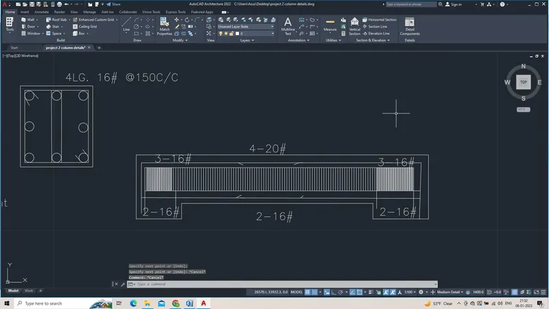
Given above is a typical beam reinforcement detail of size : 450 x 550 mm
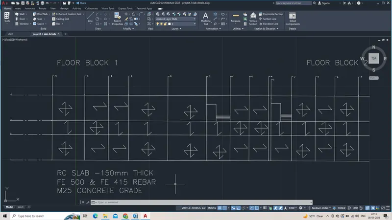
Given above is a typical slab detail of thickness : 150 mm
BELOW ALL THE ETABS FILE , SAFE FILE , AUTOCAD DRAWINGS WITH ALL THE SCREENSHOTS ARE PROVIDED