Week 9 Challenge
Q1) Design of dual slope (pitched) roof frame
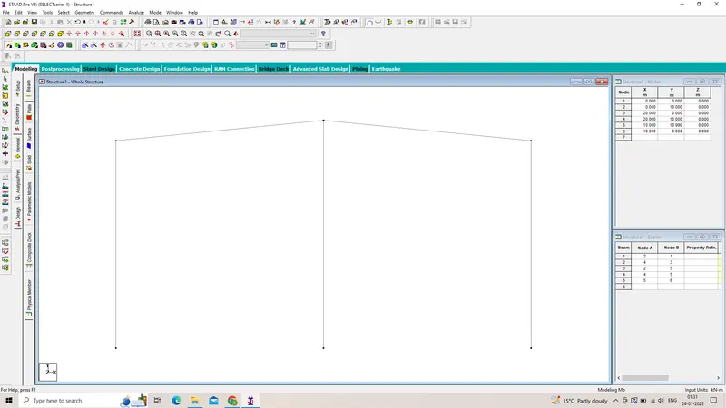
Given data : A 3 hinged pitched roof frame of a steel building.
No wind load acting on the walls and roof.
The slope of the roof is 1 in 10 and the roof is accessible for maintenance purpose (assume 75 kg/m2) only.
Given bay spacing as 5 m and frame width is 20 m.
Assuming column height 5 m.
Column property be ISMB 400
Rafter property assigned as ISMB 350
Design code as per AISC:ASD.
No seismic load considered
Weight of roofing sheet = 5kg/m2
Weight of purlins + tertiary members =25 kg/m2
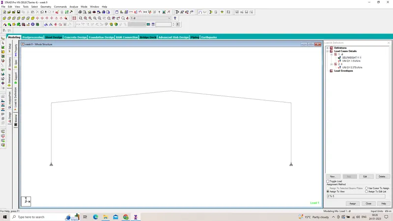
Frame is designed with all structure members and supports
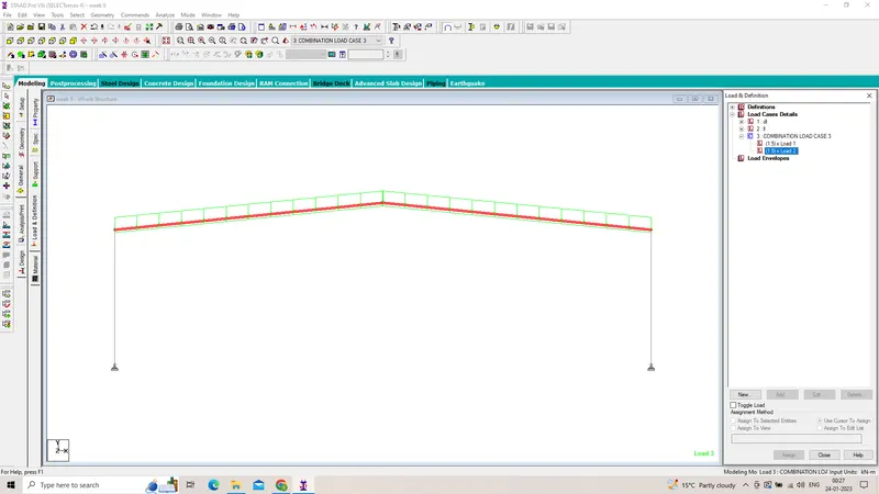
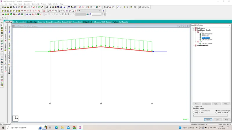
Members are assigned with loads.
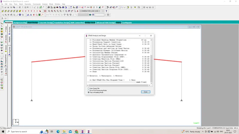
Analysis is done and found no errors , 1 warnings and 1 note
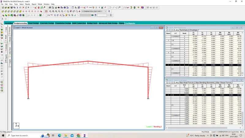
Post processing shows the bending moment
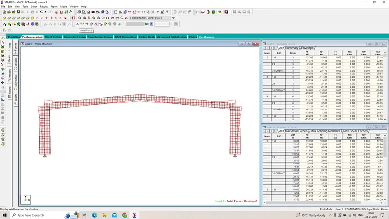
SHows the axial forces.
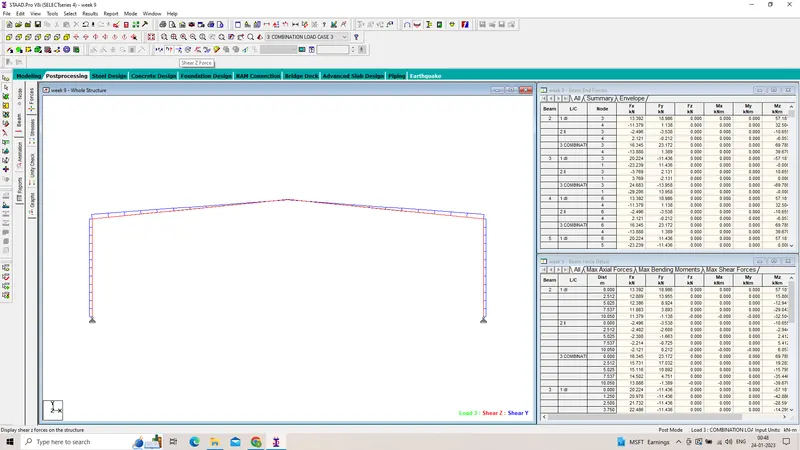
Post processing for shear force.
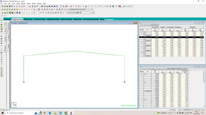
This shows the deflection/ displacement
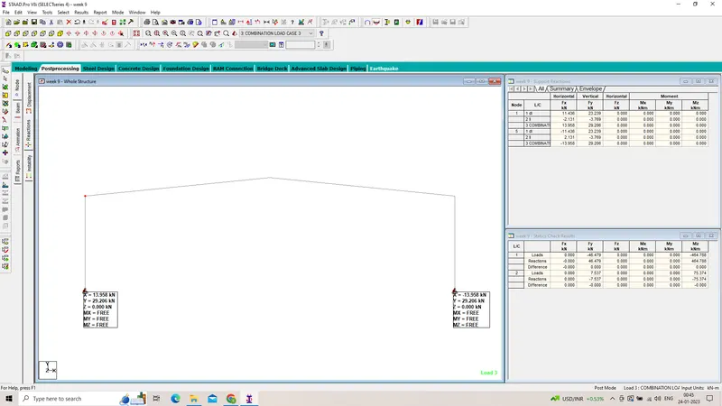
The reaction forces generated at the supports.
The model is designed and analysis conclude zero errors and 5 warnings.
Stadd file is attached below.
Q2) Bending Moment diagram
Figure 1 - Frame designed with all the loadings, supports and structural properties
Span length - 20m
Column height - 10m
Slope - 5.71 degrees
Loading on rafter - 20kN/m
Nodal loads - 10 kN/m
End columns - Fixed support
Middle columns - hinged support
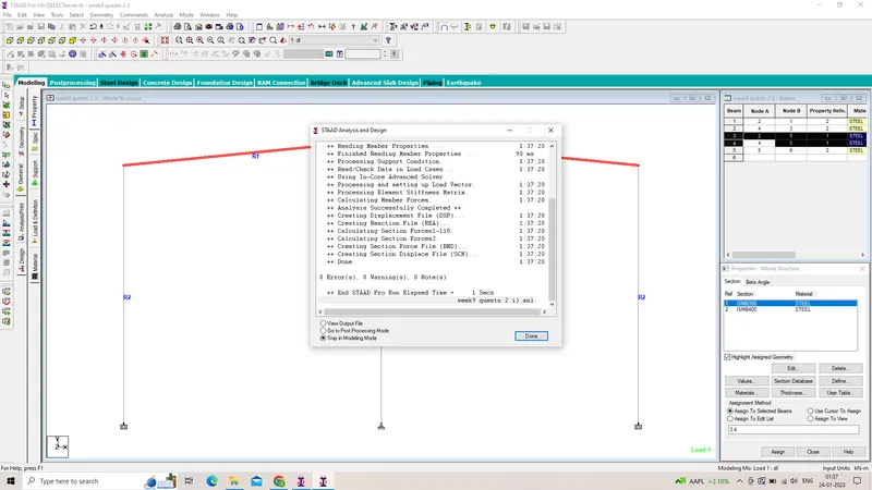
Analysis is concluded with zero errors
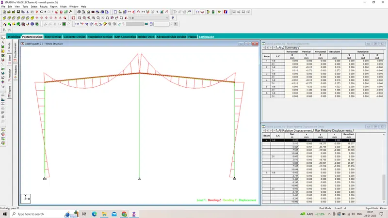
Bending moment for the required frame
Stadd file attached below
Figure 2- Frame designed with all the loadings, supports and structural properties
Span length - 10m
Column height - 20m and 16.603m
Slope - 20 degrees
Loading - 10kN/m
Nodal loads - 30 kN/m
End columns - Pinned support
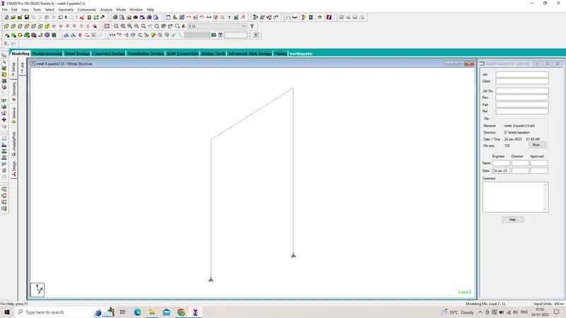
Frame designed with all loadings and support conditions.
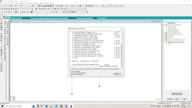
Analysis conclude zero errors.
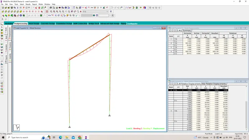
Bending moment for the required frame
Stadd file attached below
Figure 3- Frame designed with all the loadings, supports and structural properties
Span length - 8m
Column height - 10m
Loading - 2kN/m
Nodal loads - 10 kN/m
End columns - Pinned support ,also beam hinged at top
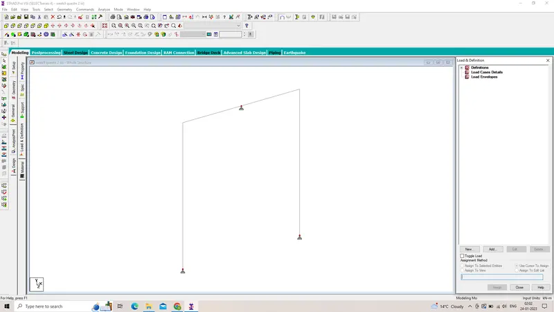
Frame ready with all structure members and supports
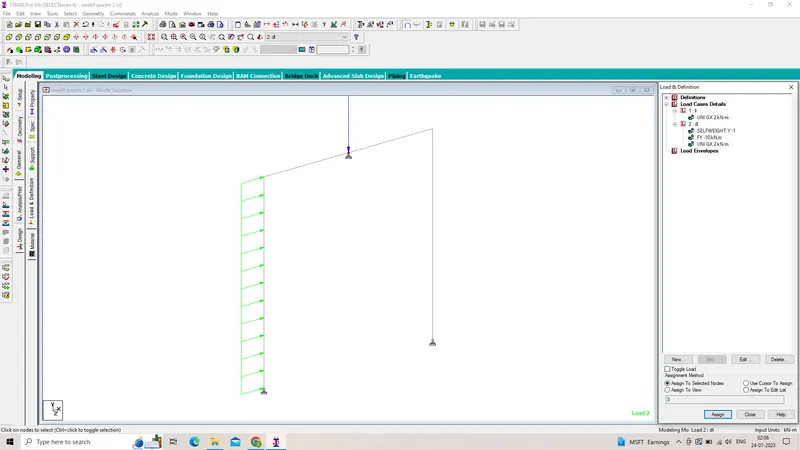
Loadings applied on the frame
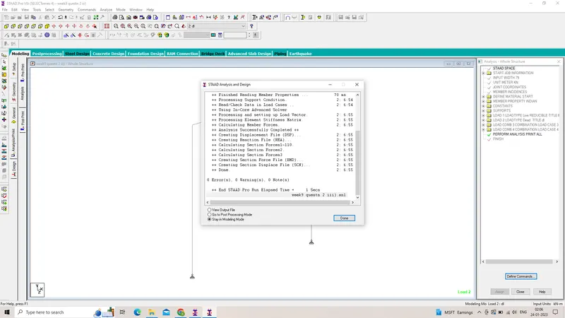
Analysis concluded with no errors and no warnings.
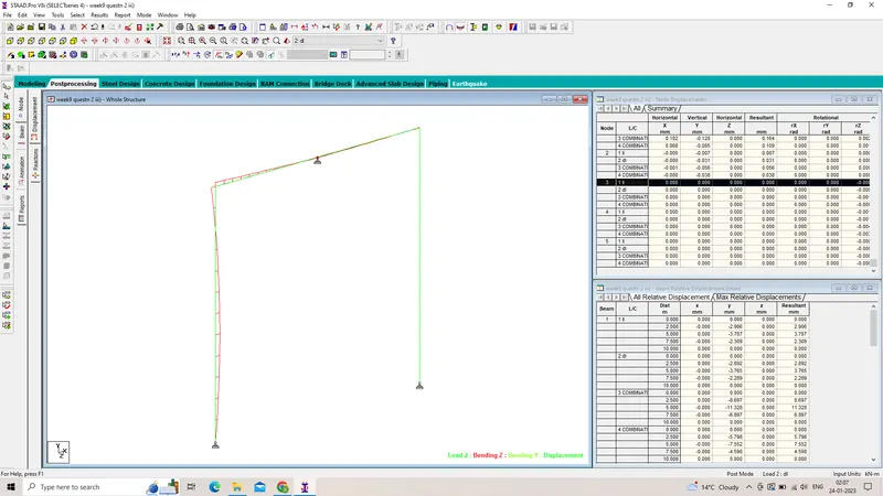
Bending moment for the desired frame
Stadd file attached below
Q3) Deflection of a frame
Figure 1
The lateral deflection at point A - 0.727 mm
- 22.626 mm 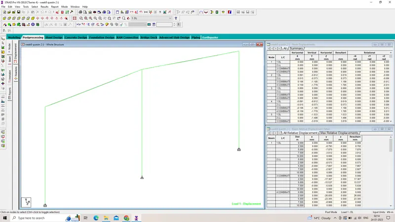
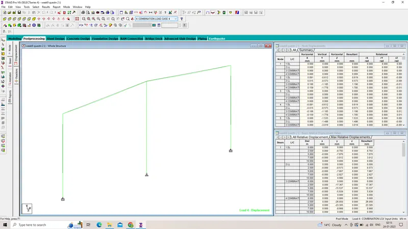
Figure 2
The lateral deflection at point A - 931.174 mm
Vertical deflection at mid section of beam between A & B - 629.147 mm
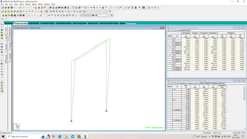
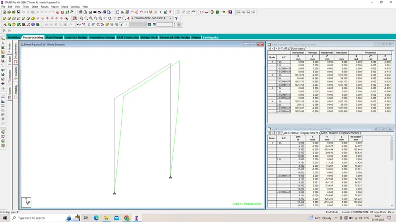
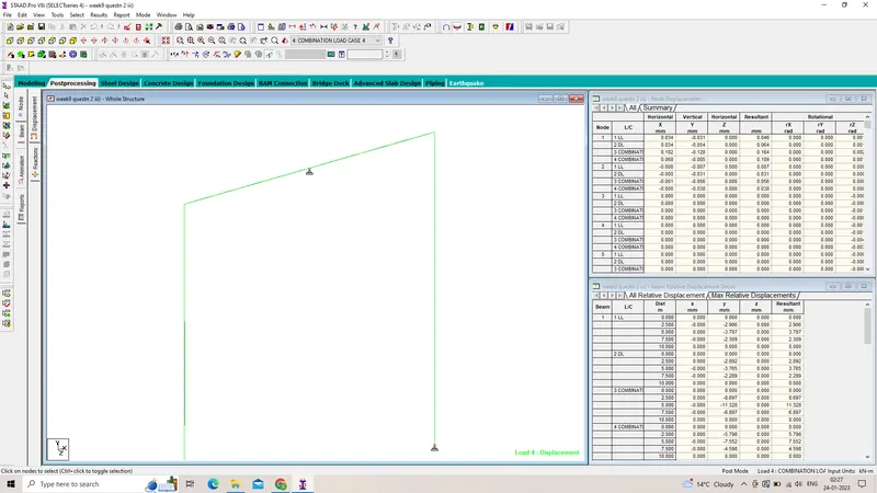
Figure 3
The lateral deflection at point A - 0.11 mm
The lateral deflection at point B - 0.00 mm
STADD FILES ALREADY ATTACHED