Analysis & Design of RCC shear walls in the model using ETABS
A G+6 building is provided. We have to design the RCC shear wall.
The shear wall of size 300x1500 at grid A-11 in the structural model.
After running the analysis , the longitudinal steel ratio, boundary element length and shear reinforcement ratio are as follows:
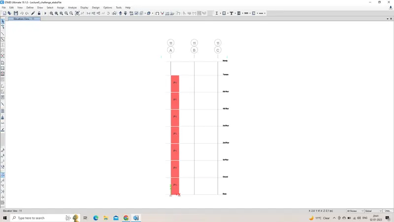
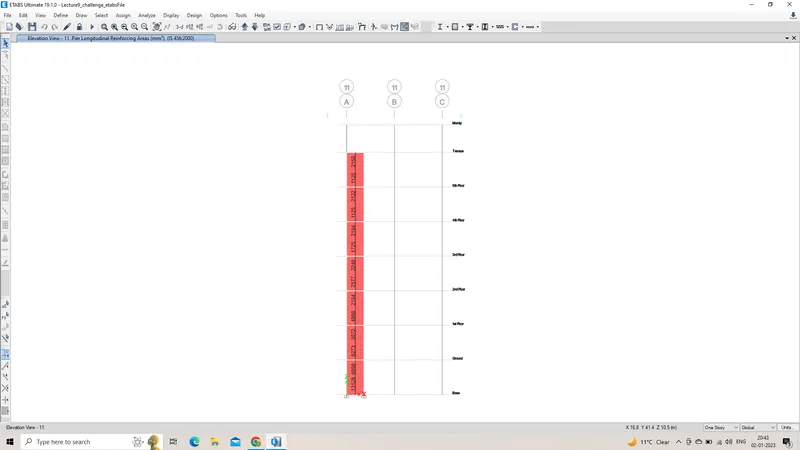
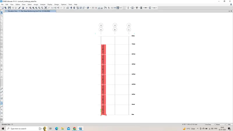
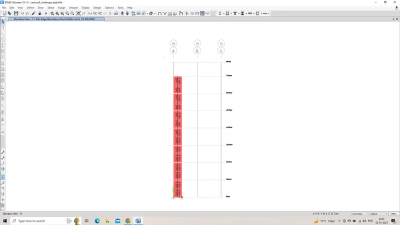
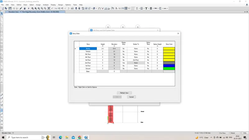
The total elevation height of the building from the basse to terrace : 23.4m
DETAILING GUIDELINES FOR SHEAR WAALLS :
a) minimum reinfrocement for shrinkage and temperature
b) ultimate limit state design rebar requirement
c) ductility rebar requirement
whichever from them is greater , should be drawn in RCs shear wall detailing
Classification of shear wall as per IS code -13920-2016 clause 10.1.4 - SLENDER WALL
h/L = 21000/1500 = 14> 2
Minimum net vertical reinforcement as per IS- 13920-2016 Table -1 (iii)= 2363 mm^2
= 0.0025+0.01375 (300/1500)
Minimum vertical reinforcement within boundary element table -1 (iii)
1440mm^2 on left (600mm width boundary element )
1080mm^2 on right (450mm width boundary element )
Minimum horizontal reinforcement as per IS- 13920-2016 Table -1 (iii)
p=0.0025 which is same 750mm^2/m
Maximum diameter of rebar for shear wall as per IS code 13920- 2016 clause 10.1.8
1/10th of wall thickness = 300/10=30mm
Commercial rebar diameter 25mm shall be adopted
Confining reinforcement within boundary element as per IS code 13920-2016 clause 10.4.4
As= 452mm^2
Confining reinforcement spacing for boundary element as per IS code 13920-2016 clause 10.4.4
a) 1/3 of minimum member dimension = 300/3 = 100mm
b) 6 times smallest main rebar = 6*25 = 150mm
c) 150mm permissible if vertical bars are spaced at maximum 200mm
MAXIMUM SPACING OF CONFINING REINFORCEMENT IN BOUNDARY ELEMENT 150mm
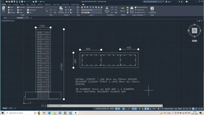
FIND THE ATTACHED AUTOCAD FILE AND SCREENSHOTS BELOW.