Project 2
AIM: -
Design and modeling of Fuel Cell Hybrid Electric vehicle, and, run simulations, change the threshold, create plots and measure current and hydrogen consumption.
Simulation Model:
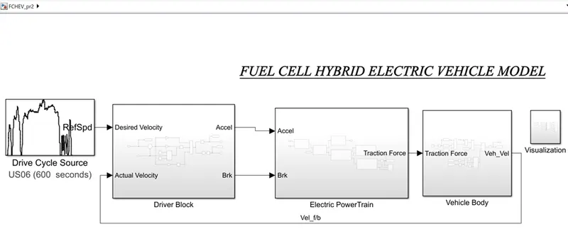
The total model is divided into 3 main blocks
- Driver Block
- Electric Power Train
- Vehicle Body
1. Driver Block:
The Driver block implements a longitudinal speed-tracking controller. Based on desired and feedback velocities, the block generates normalized acceleration and braking commands that can vary from 0 through 1 &-1. The controlling is done by the modeled PID controller.
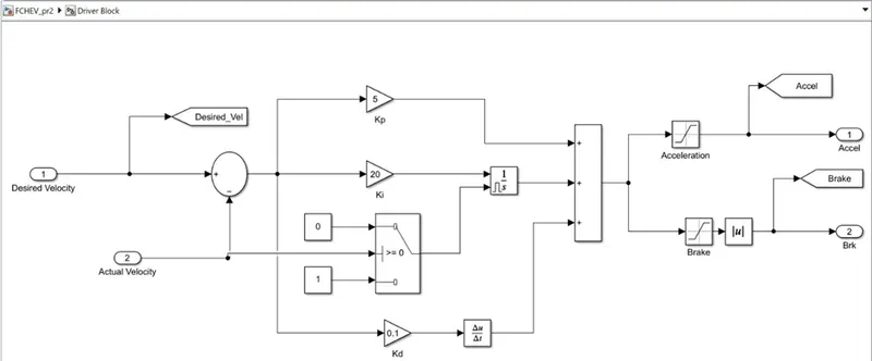
The threshold of Acceleration is 0 to 1, Braking is 0 to -1, and the final command of the absolute value of the threshold varies from 0 to 1.
The manual tuning of PID gains is done till the desired result is achieved.
2. Electric Powertrain Block:
The electric Power train block consists of the following Block which converts the driver commands to Traction Force to the vehicle generated by the motor by consuming the energy from ESS and Fuel cell system.
- Torque Requirement Calculation
- Power Calculation
- Tractive Force
- Energy Management System
- Energy Storage System & Fuel cell System.
2.a. Torque Requirement Calculation:
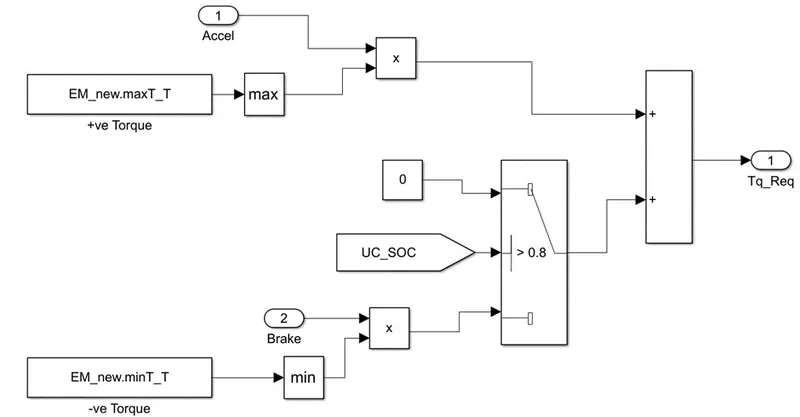
The electric motor’s positive torque values were assigned to the torque calculation of acceleration command and the negative torque values were assigned to the torque calculation while braking. Here applied the condition when the Ultracapacitor’s SOC is greater than 80% then the electric braking will work and pass the braking torque of the motor else the Mechanical braking will work by default.
The summation of both torques will give the actual torque required to generate power that will deliver the tractive force to the vehicle.
2.b. Power Calculation:
The power will be calculated by the product of angular velocity acting on the wheels(front) and the torque delivered by the motor with respect to the motor efficiency.
So that to get the torque values according to the angular velocity while accelerating and braking, fed the motor data of max torque and min torque according to it angular velocity when the torque changes dynamically.
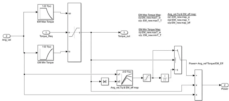
To get the motor efficiency, fed the data of angular velocity and torque vs motor efficiency. Here applied the condition of when the torque is negative then the reciprocal of the efficiency values will get calculated and the threshold range of the efficiency is 1 to 0.001 because the efficiency cannot be zero.
From the Power-calculation block will get the 2 outputs are the Torque out which will be fed to calculate the tractive force and the Power demand of the motor will be fed to the Energy management system of ESS (Battery+UC) and Fuel cell.
2. b.i. Tractive Force:
The Tractive Force Block Is the combination of the Transmission system(gearbox) and the braking system applied on the wheels.
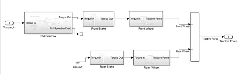
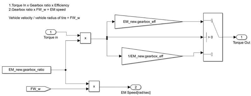
Gear Box:
The equation governed by the gearbox was
- Torque In x Gearbox ratio x Efficiency=Torque out from gearbox
- Gearbox ratio x Angular velocity of front wheel = EM speed
- Vehicle velocity/vehicle radius of tire = Angular velocity of front wheel
- Gearbox ratio x Angular velocity of front wheel =Electric Motor speed in rad/sec
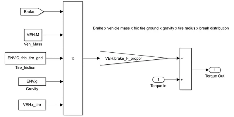
Front Brake:
The equation governed by the Front Brake was
(Brake x vehicle mass x friction tire ground x gravity x tire radius x brake distribution) -Torque applied
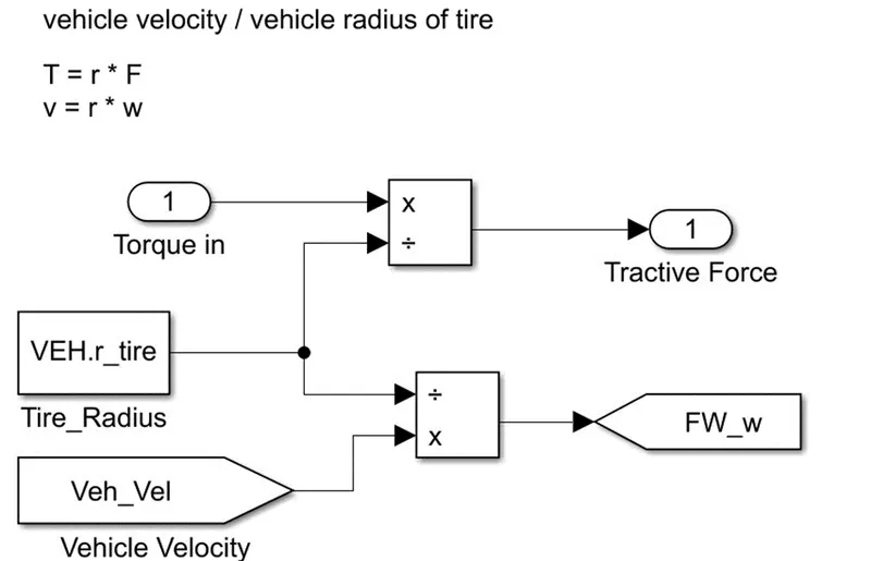
Front Wheel:
The force and the brake applying on the wheel can be defined as
- Tractive Force = Torque/vehicle radius
- Vehicle velocity/vehicle radius of tire = Angular velocity of front wheel
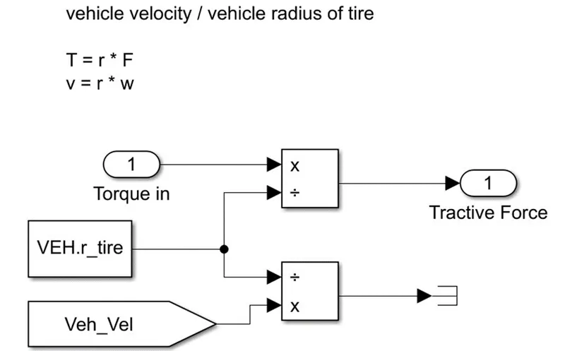
Rear Wheel:
The force and the brake applying on the wheel can be defined as
- Tractive Force = Torque/vehicle radius
- Vehicle velocity/vehicle radius of tire = Angular velocity of rear wheel
Rear Brake:
The equation governed by the Rear Brake was
(Brake x vehicle mass x friction tire ground x gravity x tire radius x brake distribution) -Torque applied
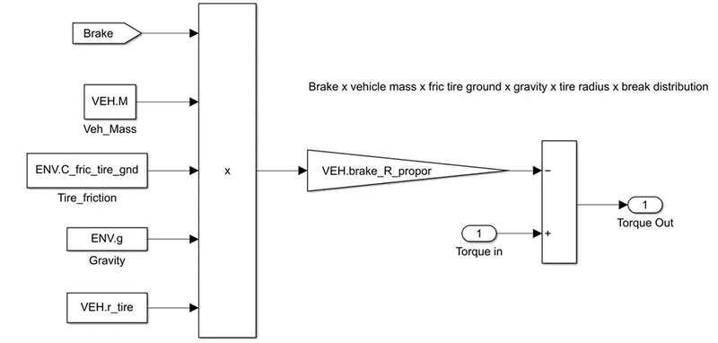
The torque input of the rear wheel is given to the ground since the vehicle running by the front axial and the angular velocity of the rear wheel is not considered it is the same as the front wheel’s angular velocity.
The summation of the traction force of the front wheel and rear wheel will give the traction force of the vehicle.
2. b. ii. Energy Management System:
Energy management strategy (EMS) is an important link during the HEV/PHEV design procedure, which can govern the energy flow between the fuel tank and the electric energy storage by solving the energy distribution problem as well as maintaining the state of charge of the energy sources. With the continuous development of intelligent connected vehicle technology, designing an efficient EMS with vehicle-to-infrastructure/vehicle-to-vehicle.
Considering that to model a system the total power demand is in the range of (0 to inf) kW. The energy system strategy of the system is following as shown below.
|
Power Demand |
Conditions |
Energy Source |
|
0-9999 |
If UC_SOC >35% |
UC |
|
If UC_SOC <35% |
Fuel Cell |
|
|
10000-22999 |
If SOC_Batt >35% |
Battery |
|
If SOC_Batt<35% |
Fuel Cell |
|
|
23000-54999 |
No Condition |
Fuel Cell |
|
55000 -Inf |
If UC_SOC >35% |
UC |
|
If UC_SOC<35% |
FC |
Flow Chart for the positive power distribution
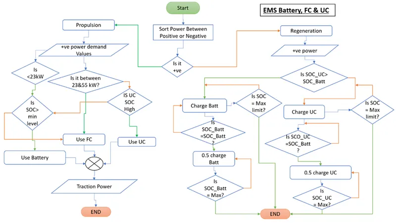
EMS_Battery_FC&UC Model
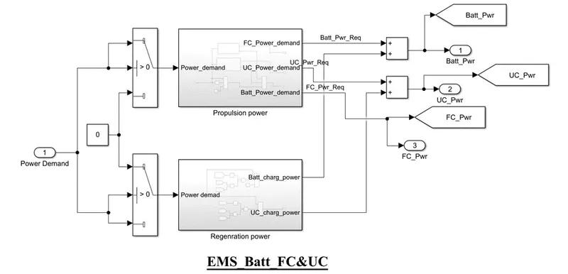
The Power demanded by the motor will check whether it is Positive power or Negative power, positive power will be propulsion power that drives the vehicle by consuming the energy from the ESS and Fuel cell system. The negative power that is generated by the motor while the deceleration or braking period will be fed to the UC system or Battery system to get charged.
As mentioned, the power delivery range by the systems the modeling of the EMS of Propulsion power
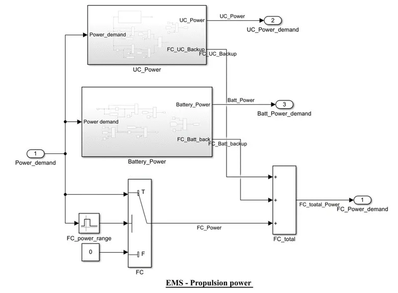
EMS_Battery
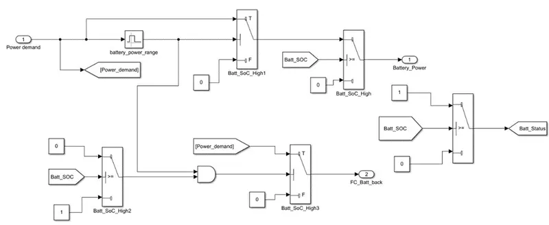
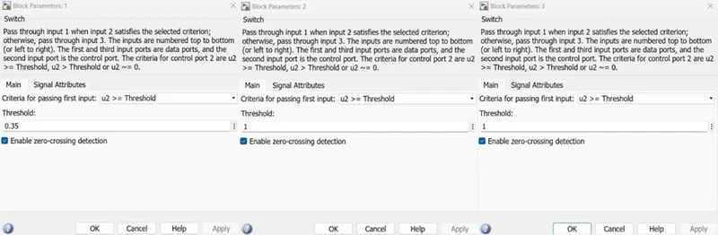
In the Battery system, if the power demand is between 10000 to 22999 watts and the battery SOC is > 35% then the power supply will be provided from the Battery system.
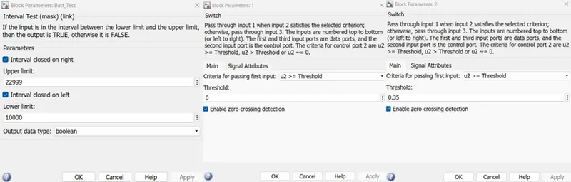
If the power demand in the limit of the system and the SOC is <35% then the power supply will be provided Fuel cell system as the backup to the Battery system if that Battery SOC is >= 35% if the condition satisfies then it will pass 0 else it will pass 1 and when the Batt_Test passes 1 and the SOC condition passes 1 then only the power supply will provide by the Fuel system.
EMS_UC
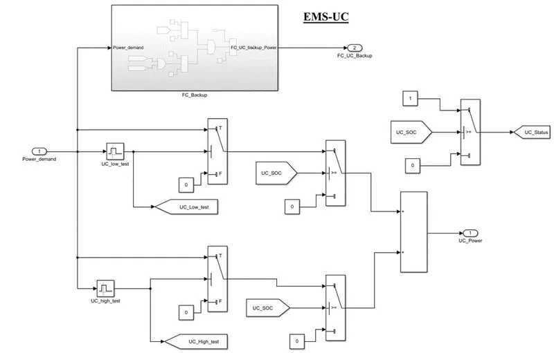
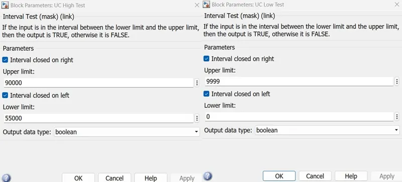
The Ultracapacitor system will deliver the power when the 0-9999 watts is considered as low power demand or it will deliver the power when the 55000 -90000 watts is considered as high-power demand. Any power demand in both will be delivered only when the SOC of the UC system is >0.35%.
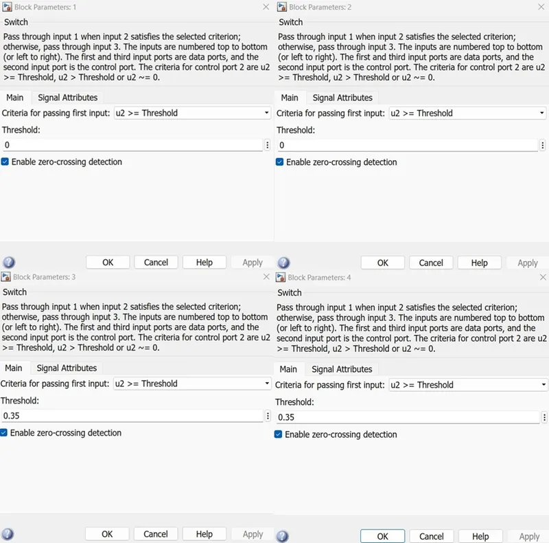
If the UC system’s SOC is <35% then the same power demand will be delivered by the Fuel cell system back to the UC system.
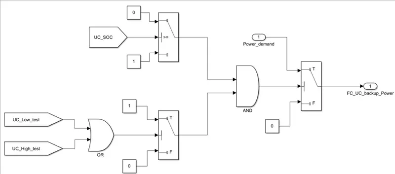
Either the Low power range or the High-power range demand getting as the input then the switch will pass 1 and when the UC SOC is <35% switch will pass 1 when both states were in on condition then the required power demand will be delivered by the FC system.
EMS_FC
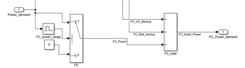
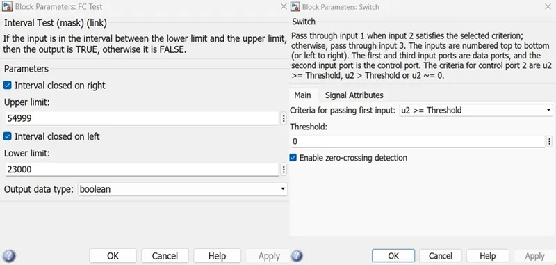
The Fuel cell system will deliver when the power demand is in the range of 23000-54999 watts as well as when the SOC of the UC system and SOC of the Battery system is <35%.
When this condition happened then the backup system of Battery and UC will come into the picture and the total power demand of the system will be provided by the Fuel cell system.
2. b.iii. Energy Storage System & Fuel cell System:
BATTERY SYSTEM
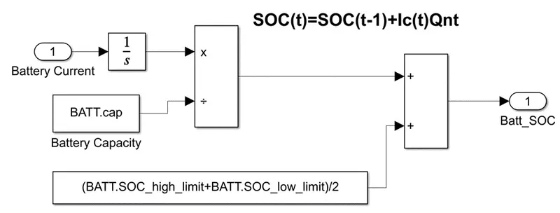
Battery SOC
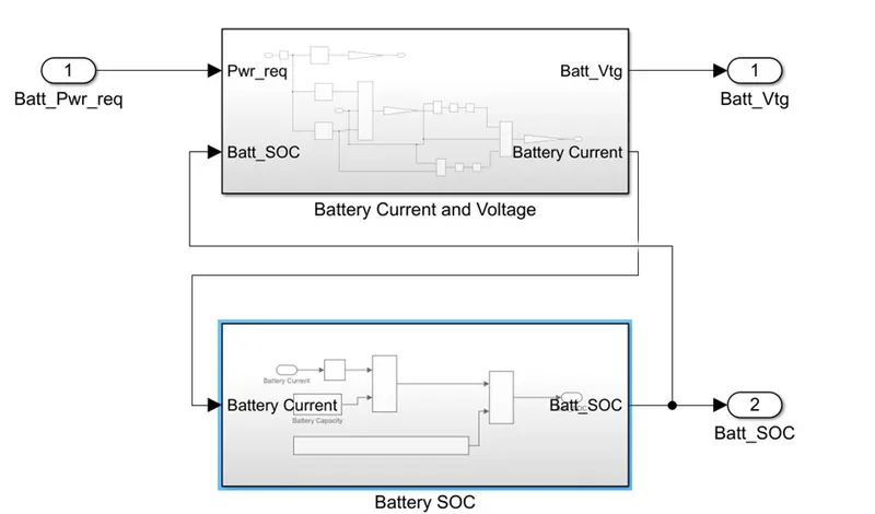
The Battery SOC can be defined as SOC(t)=SOC(t-1)+Ic(t)Qnt
Battery Current and Voltage
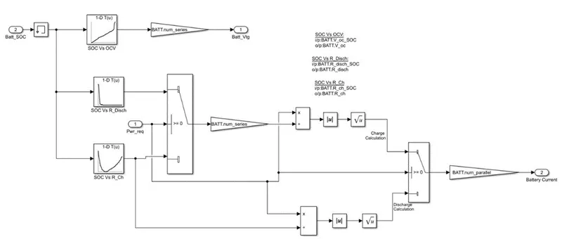
To calculate the Battery voltage fed the data of battery SOC vs OCV and the resultant OCV multiplied by the no. of cells in the series of the battery pack.
To calculate the Battery current, need the resistance of the battery while charging and discharging so that data of Battery SOC vs Resistance discharge and Battery SOC vs Resistance Charge is accordingly if the power demand is positive then the discharge resistance will come and calculate the discharge current else if the power demand is negative then the charge resistance will come and calculate the charge current. We know that the in-series connection resistance will get add up so that the total resistance will be the product of the resultant resistance value and the no. of cells in the series.
We know that Power = I^2*R from this current I =sqrt(P)/R, again the checked with the power demand whether the current is charging current or discharging current. The total current can be given by the product of the resultant current and the no. of cells in parallel.
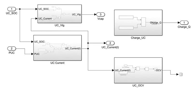
ULTRA-CAPACITOR SYSTEM
UC SOC
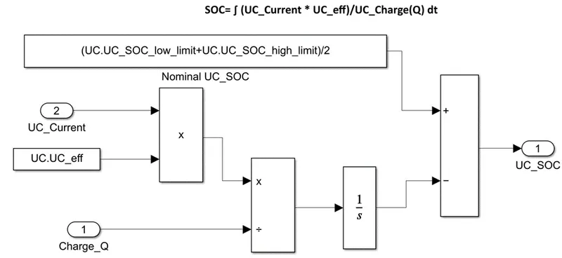
The SOC equation:
SOC= ∫ (UC_Current * UC_eff)/UC_Charge(Q) dt
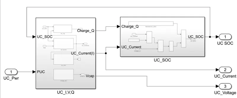
The current flowing through the circuit when integrated gives the charge flown through the circuit. Taking a ratio of it over the total charge capacity gives SOC.
UC Voltage, Current, and Charge
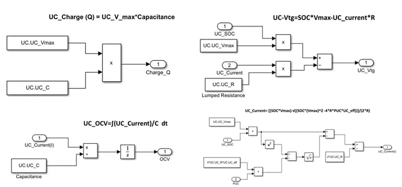
- Total Charge capacity(Q) depends on the capacitance which is the charge storage capacity measured in Farads.
UC_Charge (Q) = UC_V_max*Capacitance
- Open Circuit Voltage(OCV) is a measure of the electric field between the plates.
UC_OCV=∫(UC_Current)/C dt
- The current consumed is calculated which is fed into a SOC calculation Block. The SOC is then calculated based on the amount of current drawn and pushed back into UC.
UC_Current= [(SOC*Vmax)-√((SOC*(Vmax)^2-4*R*PUC*UC_eff))]/(2*R)
- Output Voltage of a UC depends on the SOC, Max voltage of the UC provided by the OEM, and current of the UC along with lumped resistance of the UC
UC-Vtg=SOC*Vmax-UC_current*R
FUEL CELL SYSTEM
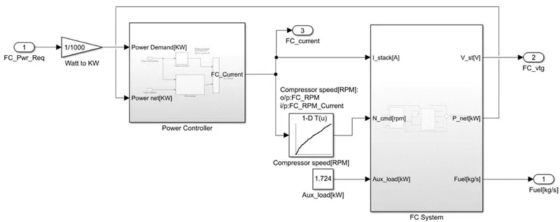
The fuel cell system consists of a Fuel cell stack that is supported by a power controller
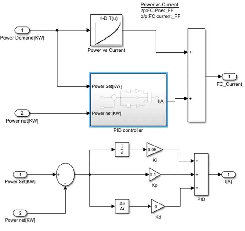
FCS Power Controller
The power control consists of a simple PID controller that will provide the stack current by taking the reference of demanded power and the net power of the fuel cell stack. To do that Power net vs Stack current OEM data need to be fed so that accordingly the power demand of the stack current will be delivered.
Fuel cell Stack system
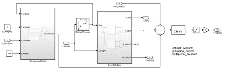
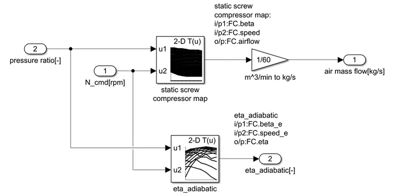
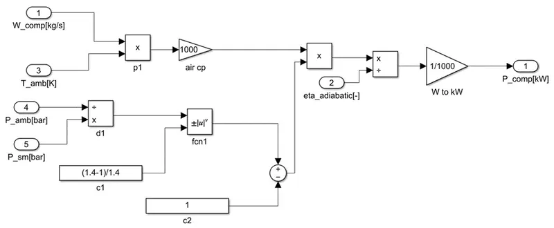
The fuel cell Stack system consists of Compressor and a fuel cell. The stack current will be fed to the current vs compressor rpm so that the compressor will receive the speed command. The auxiliary load of the vehicle is also satisfied by the fuel cell system.
Compressor Model
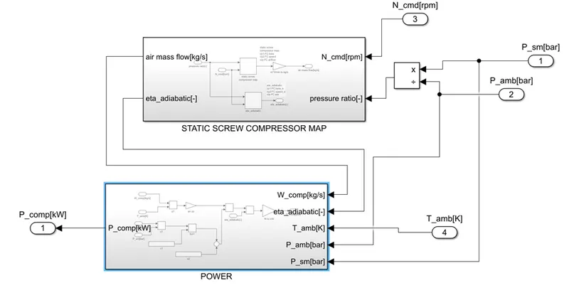
Static Screw Compressor
Compressor Power
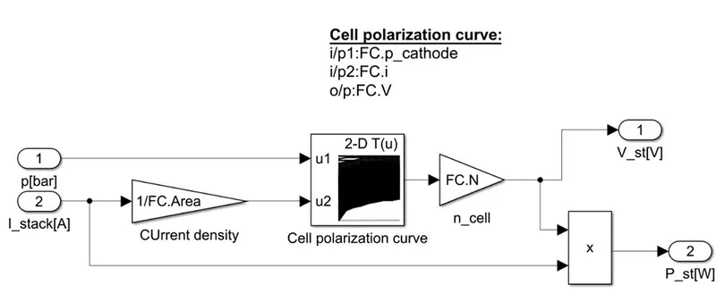
Fuel Cell Stack

Stack Voltage
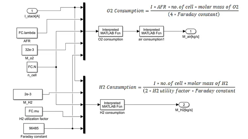
AIR and H2 Consumption
3. Vehicle Body Block:
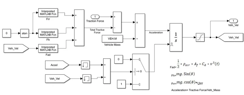
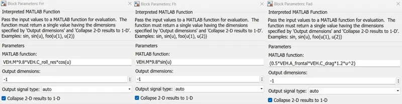
All these forces are added as shown above and subtracted from the Torque force. This resultant force is divided by the Mass to get the acceleration of the vehicle
- F = M*a
- a = F/M
- a= acceleration of the vehicle
- F = resultant force
- M = mass of the vehicle
This acceleration is integrated to get the velocity. The integrator is provided by a Level trigger to reset it because it avoids the Integral Windup. Whenever the velocity or Acceleration of the driver pedal is zero the integrator should be reset otherwise it will get into Integral windup i.e., it is going to take the previous value to evaluate and even if the velocity is zero the out of the integrator will increase. After integrating it we need to limit it to a positive speed because the negative speed will appear when the vehicle is going in reverse.
RESULTS:
1.Desired Velocity Vs Vehicle Velocity:
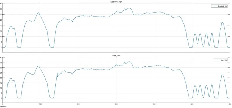
The above plot explains that the vehicle velocity followed the desired velocity demanded by driver.
- Battery and UC: Status, SOC and Power
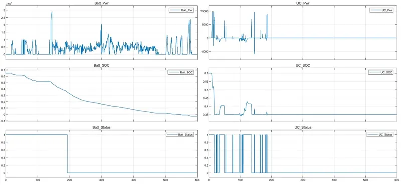
The above plot explains the status of the Battery, and UC system when getting On and Off and the power delivered.
- Battery, UC and FC Power Consumption and SOC
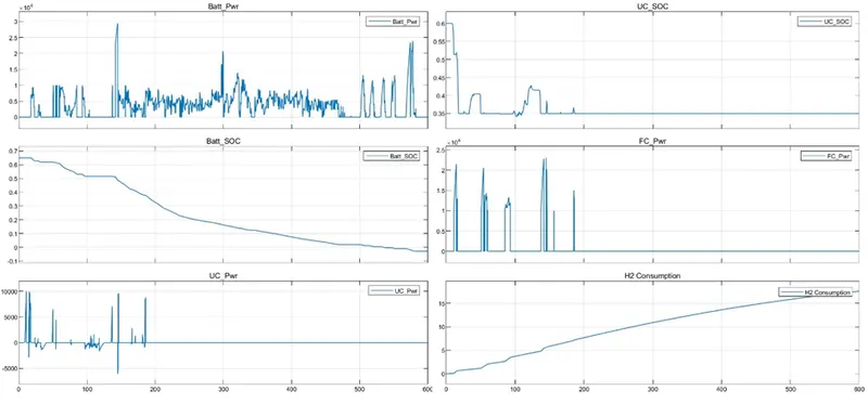
The above graph explains that Fuel cell systems consumed H2 fuel: 23kg
Project Perquisites
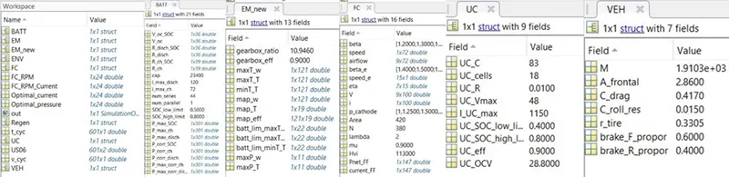
Need to load the mat files shown below