Project-1: Powertrain for aircraft in runways
Q1.
Search and list out the total weight of various types of aircraft.
ANS: -
AIRCRAFT: - An aircraft is a vehicle or machine that is able to fly by gaining support from the air. It counters the force of gravity by using either static lift or by using the dynamic lift of an airfoil, or in a few cases the downward thrust from jet engines.
All of them have propellers and wings or machinery to run through the air. However, they may vary according to size, type, usage, and more.
Classification: -
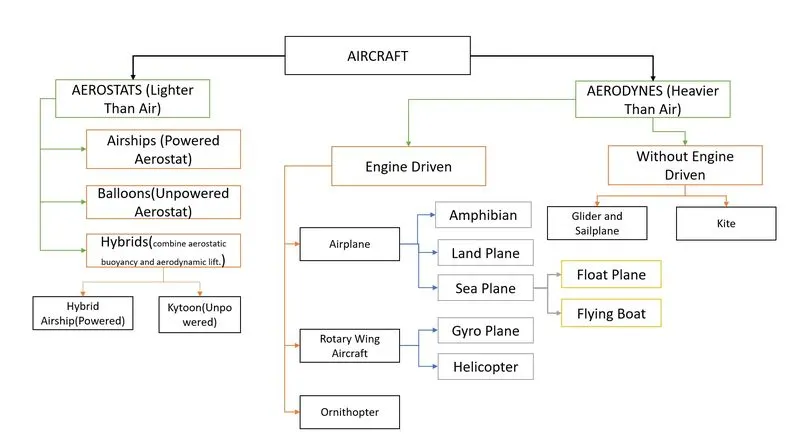
In most common terms, there are two types of classifications for aircraft.
- Lighter than air aircraft, known as aerostats
- Heavier than air aircraft, called aerodynes.
AEROSTATS: lighter than air aircraft are very lightweight in weight. These types of light aircraft generally use buoyancy like ships, which helps them float in the air. Low-density gas such as hydrogen, helium, or hot air balloons is used to fill in the aircraft, when the weight of this is added to the weight of the aircraft structure, it adds up to the same weight as the air that the craft displaces. This low-density gas is lighter than air, hence the name. The most common types of aerostats known to us are hot air balloons and sky lanterns.
AERODYNES: Heavier than air aircraft is much higher in weight and size. They push the gas or air downwards (by Newton's laws of motion), which reaction helps to make aircraft upward. Since these are dynamic through movements in the air, they are called aerodynes. This dynamic lift through the air can be caused mostly by mechanisms.
There are two ways to produce dynamic upthrust aerodynamic lift, and powered lift in the form of engine thrust.
Aerodynamic lift involving wings is the most common, with fixed-wing aircraft being kept in the air by the forward movement of wings, and rotorcraft by spinning wing-shaped rotors sometimes called rotary wings. A wing is a flat, horizontal surface, usually shaped in cross-section as an aerofoil. To fly, air must flow over the wing and generate lift. A flexible wing is a wing made of fabric or thin sheet material, often stretched over a rigid frame. A kite is tethered to the ground and relies on the speed of the wind over its wings, which may be flexible or rigid, fixed, or rotary.
Powered lift, the aircraft directs its engine thrust vertically downward, take-off and lands vertically using the powered lift, and transfers to the aerodynamic lift in a steady flight.
- In the category of fixed-wing aircraft, the entire mechanism is relied upon forwarding speed to create airflow all over the wings.
- In the category of rotorcraft, which uses spinning rotors that are like wings. The helicopter is the most commonly known aircraft under this classification.
Types Of Aircraft with the most common classification, categories, and subcategories under the aircraft were given below:
List of weights of a few Various Types of Aircraft:
|
Aerostat |
Example Model |
Weight (kg) |
|
Airships |
Detroit ZMC-2 |
340 |
|
Balloons |
Hot-air Balloon |
360 |
|
Kytoon |
Heli kite |
117 |
|
Aerodyne |
||
|
Amphibian |
Grumman Turbo Mallard GF73T |
6350 |
|
Land Plane |
Suerstol XL |
1412 |
|
Float Plane |
Canadair CL-415 |
5842 |
|
Flying Boat |
A41 Factory VNS-41 |
780 |
|
Gyro Plane |
AG-915 |
344 |
|
Helicopter |
HAL Dhruv |
2520 |
|
Cargo plane |
Boeing 747 F Freighter |
1,12,760 |
|
Glider & Sailplane |
Rolladen-Schneider LS4 |
472 |
Q2.
Is there any difference between ground speed and airspeed?
ANS: -
Ground speed: The velocity of the object measured relative to the ground is called the ground speed, here object can be defined as the aircraft and its horizontal speed relative to the surface of the Earth.
Airspeed: The important quantity in the generation of lift is the relative velocity between the object and the air, which is called the airspeed. Airspeed cannot be directly measured from a ground position but must be computed from the ground speed and the wind speed. Airspeed is the vector difference between the ground speed and the wind speed. On a perfectly still day, the airspeed is equal to the ground speed. But if the wind is blowing in the same direction that the aircraft is moving, the airspeed will be less than the ground speed.
“The relationship between airspeed and ground speed is fairly simple. Ground speed is simply the sum of airspeed and wind speed”.
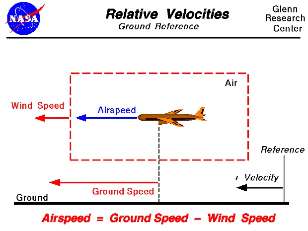
- If the aircraft is flying in the same direction as the wind is blowing, the aircraft experiences a tailwind, and its ground speed is higher than its airspeed. On the other hand, if the wind is blowing against the direction the aircraft is traveling in, the aircraft experiences a headwind, and its ground speed is lower than its airspeed.
To give you an actual example, imagine an aircraft that cruises at an airspeed of 500 miles per hour that has to cover a ground distance of 2,000 miles.
- If there is no wind at all, then both the aircraft’s airspeed and ground speed would be the at same 500 miles per hour, and the aircraft would reach its destination in four hours.
- If there was a 100 miles per hour headwind – wind blowing against the aircraft’s direction of travel – the aircraft would still be traveling at an airspeed of 500 miles per hour. However, its ground speed would be just 400 miles per hour (100 miles per hour slower than its airspeed). And as such, it would take the aircraft five hours to reach its destinations.
- Finally, if there was a 100 miles per hour tailwind – wind blowing in the same direction as the aircraft’s travel – the aircraft would still be traveling at an airspeed of 500 miles per hour, but its ground speed would be 100 miles faster.
- And, at 600 miles an hour, the aircraft would reach its destination in just three hours and twenty minutes.
- The above is the reason why some flights go “out of their way” to avoid headwinds or catch tailwinds. And, why some flights might appear to be traveling at “supersonic speeds,” even though their airspeed – the speed that would actually matter in determining whether or not the flight truly is supersonic – is subsonic.
For pilots, both airspeed and ground speed was very important. While the first one helps them make sure they are flying fast enough to take off, not stall, and so on, the second one helps them figure out how long it will take them to get from one place to another.
On the other hand, if you are a passenger, you will only need to be concerned about the ground speed as that will tell you how fast are you flying from your origin to your destination.
To visualize these speeds an animation by NASA in the given link.
https://www.grc.nasa.gov/www/k-12/airplane/Animation/airrel/anrelw.html
Q3.
Why is it not recommended to use aircraft engine power to move it on the ground at the Airport?
ANS: -
Aircraft are designed to fly. When they’re going to spend more than 15 hours in the air, they need to perform as efficiently as possible. From getting the most power out of the engines to maximizing the lift from the wings, the main part of the design process is focused on the airborne aspect, and at the same time after landing aircraft needs to reach the terminal building.
The area on which aircraft move on the airfield can broadly be separated into three separate categories. The ramp, or apron, is where the stands are located for aircraft to park. The runways are what the aircraft used to take off and land. And the taxiways, which they use to get between the two.
Apron – A defined area, on a land aerodrome, intended to accommodate aircraft for purposes of loading or unloading passengers, mail or cargo, fuelling, parking, or maintenance.
Runway – According to the International Civil Aviation Organization (ICAO), a runway is a “defined rectangular area on a land aerodrome prepared for the landing and take-off of aircraft”. Runways may be man-made surfaces (often asphalt, concrete, or a mixture of both) or a natural surface (grass, dirt, gravel, ice, sand, or salt).
Taxiway – A defined path on a land aerodrome established for the taxiing of aircraft and intended to provide a link between one part of the aerodrome and another.
Parking or Aircraft stand – A designated area on an apron intended to be used for parking an aircraft.
Aircraft move using their own engine power all the time on the airport apron and taxiways under their own power to go towards runways and after landing taxi to their assigned gate.
The obvious problem with parking facing the terminal is that in order to get to the runway, aircraft need to move back-ward off the stand first, aircraft are unable to do this as they don’t have a reverse gear. The only time they use external assistance is to push back from the gate. Large turbofan aircraft need help to reverse by a pushback tractor. The engines are turned on after the pushback is complete and the aircraft can move forward under Its own power.
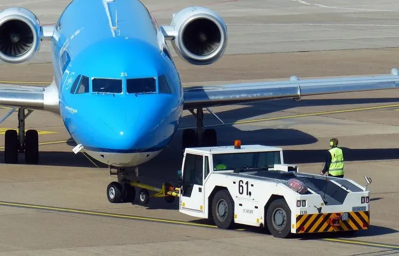
It is easier for the pushback tractor driver to see the outside and drive the vehicle compared to the pilot. It will save fuel for aircraft by not being used for this kind of small work. Comparatively, the fuel consumption of aircraft engines is very high than the fuel consumption of tractors for this kind of work.
To be accurate, some aircraft can reverse using a variable pitch prop or thrust reversing on turbofans but generally reversing is done by pushback tractors. Blasting jet reversers blows debris in the crowded gate area creating foreign object damage hazards for adjacent aircraft, gate equipment, or terminal waiting area glass windows.
Q4.
How an aircraft is pushed to the runway when it’s ready to take off?
ANS: -
- when the aircraft is ready to take off, the specialists from the airline conduct a technical check to make sure that the engines, wings, control surfaces, landing gear, instruments, doors, and other equipment are in full working order.
- The aircraft is ready for baggage to be loaded for the next flight. This is a quick process, on average taking only 10-15 minutes. A little later the passengers start boarding. As soon as they are all in their seats, the door is closed and the pilot informs air-traffic control that the flight is ready for departure.
- The apron handler removes the chocks. A so-called pushback truck reverses the aircraft into taxiing position, pushing it with a towbar attached to the nose-wheel strut. Or, in the most modern versions, by actually lifting the wheel. That speeds up coupling and decoupling.
- The aircraft taxis to the runway to depart at the agreed time.
- The pilot waits for permission to take off from air-traffic control. This is possible once the departure route is clear. As soon as the go-ahead is received, the plane takes to the air at full power.
Q5.
Learn about take-off power, tyre design, rolling resistance, tyre pressure, and brake forces when landing.
Ans: -
Aircraft Take-Off Power:
- Take-off is the first critical phase of flight pilots’ encounters.
- Normal aircraft takeoffs are the most basic of all takeoff procedures/maneuverers.
- The purpose of this maneuverer is to safely execute a takeoff under normal conditions (i.e., hard surface, minimal wind, plenty of available takeoff distance).
- Normal takeoffs are closely related to the performance of flight at minimum controllable airspeeds.
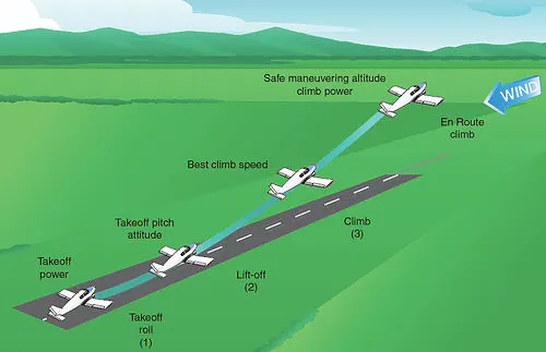
Forces Acting on the Aircraft
Thrust, drag, lift, and weight is forces that act upon all aircraft in flight. These forces work and control them with the use of power and flight controls are essential to flight.
Thrust—the forward force produced by the powerplant/propeller or rotor. It opposes or overcomes the force of drag. As a general rule, it acts parallel to the longitudinal axis.
Drag—a rearward, retarding force caused by disruption of airflow by the wing, rotor, fuselage, and other protruding objects. As a general rule, drag opposes thrust and acts rearward parallel to the relative wind.
D = 0.5*CD*ρ *V2*S
Where D=Drag; CD=ratio of drag pressure to dynamic pressure ; ρ =Air Density; V=Airfoil Velocity; S= Surface area of the wing
Lift—is a force that is produced by the dynamic effect of the air acting on the airfoil, and acts perpendicular to the flight path through the center of lift (CL) and perpendicular to the lateral axis. In level flight, lift opposes the downward force of weight.
L = 0.5*CL*ρ*V2* S
Where L=Lift; CL=Coefficient of lift; ρ =Air Density; V=Airfoil Velocity; S= Surface area of the wing
Weight—the combined load of the aircraft itself, the crew, the fuel, and the cargo or baggage. Weight is a force that pulls the aircraft downward because of the force of gravity. It opposes lift and acts vertically downward through the aircraft’s center of gravity (CG).
W=mass*gravity
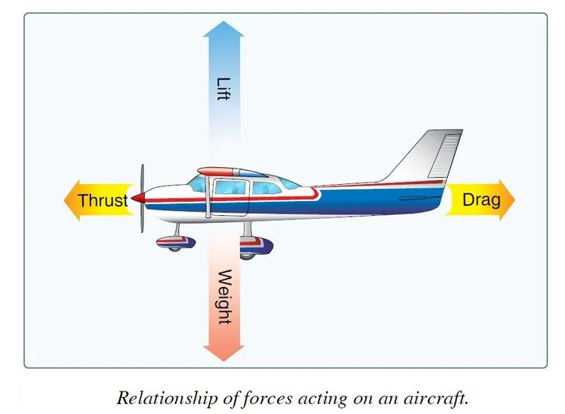
It does not mean the four forces are equal. It means the opposing forces are equal to and thereby cancel, the effects of each other.
- The sum of all upward components of forces (not just lift) equals the sum of all downward components of forces (not just weight)
- The sum of all forward components of forces (not just thrust) equals the sum of all backward components of forces (not just drag)
Take-off Power =Total force* Velocity.
Tyre design:
When it comes to safety, tyres are one of the most important components of aircraft. They help to absorb the shock of landing and provide cushioning. It also provides the necessary traction for braking and stopping an aircraft.
Design and Construction of Aircraft tyre:
An aircraft tyre is designed to withstand extremely heavy loads while landing, take off, taxing, and parking. The number of wheels required for aircraft increases with the weight of the aircraft, as the weight of the aeroplane needs to be distributed more evenly.
Carcass plies are used to form the tyre. They are sometimes called casing plies. An aircraft tyre is constructed for the purpose it serves.
- They support the weight of an aircraft while it is on the ground.
- It also provides the necessary traction for the braking and stops of aeroplanes.
- Tyre also helps to absorb the shock of landing and provides cushioning for the roughness of takeoff, roll-out, and taxi operations.
Unlike an automobile or truck tyre, it does not have to carry a load for a long period of continuous operation. However, an aircraft tyre absorbs the high impact loads of landing, and also, it’s operating at high speeds for a short time when required.
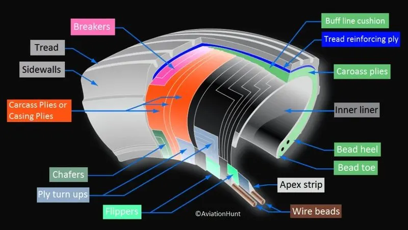
Retreading – Retreading is the method of restoring a worn tyre by renewing the tread area or by renewing the tread area plus one or both sidewalls. Repairs are included in the tyre retreading process.
Load Rating – Load rating is the maximum permissible load at a specified inflation pressure.
Ply Rating – Ply Rating is used to identify the maximum recommended load rating and inflation pressure for a specified tyre. It is an index of tyre strength.
Speed Rating – The speed rating is the maximum takeoff speed to which the tyre has been tested.
Skid Depth – Skid depth is the distance between the tread surface and the deepest groove as measured in the mould.
Sidewall – The sidewall is a protective layer of rubber that covers the outer casing ply. It extends from the tread edge to the bead area.
Tread Reinforcing Ply– One or more layers of fabric that strengthen and stabilize the tread area for high-speed operation. It also serves as a reference for the buffing process when tyres are retreaded.
Buff Line Cushion– The buff line cushion is made of rubber compound to enhance the adhesion between the tread reinforcing ply and the breakers or casing plies. It is of sufficient thickness to allow for the removal of the old tread when the tyre is retreaded.
Breakers– Breakers are reinforcing plies of rubber-coated fabric placed under the buff line cushion to protect casing plies and strengthen and stabilize the tread area. They are considered an integral part of the casing construction.
Casing Plies– Alternate layers of rubber-coated fabric (running at opposite angles to one another) to provide the strength of the tyre.
Wire Beads– Hoops of high tensile strength steel wire that anchor the casing plies and provide a firm mounting surface on the wheel. The outer edge of the bead that fits against the wheel flange is called the bead heel. The inner bead edge is called the bead toe.
Apex Strip– A wedge of rubber affixed to the top of the bead bundle.
Flippers–Layers of rubberized fabric that help anchor the bead wires to the casing and improve the durability of the tyre.
Ply Turnups–The casing plies are anchored by wrapping them around the wire beads, thus forming the ply turnups.
Chafer– A protective layer of rubber and/or fabric located between the casing plies and wheel to minimize chafing.
Liner– In tubeless tyres, the liner is a layer of low permeability rubber that acts as a built-in tube and restricts gas from diffusing into the casing plies. In tube-type tyres, a thinner liner is used to prevent tube chafing against the inside ply.
- Aircraft tyres must have an approved speed and load rating and have sufficient clearance when retracted through landing gear to allow for tyre growth. Tyre growth is the increase in the size of the tyre due to centrifugal forces at high speed.
- Tubeless tyres are more advantageous over tube-type. There is no longer the use of tube-type tyre in recent aviation. Nowadays all airliners are using tubeless tyres. Tubeless that are meant to be used without a tube have the word TUBELESS on the sidewall of the tyre.
- Almost all airliners are using Radial tyre. Bias is an older design, and it’s mainly used for road vehicles. Radial tyres have the word RADIAL on the sidewall. Radial tyres are more expensive than bias-ply tyres. Radial tyres are in demand because of their lower life cycle cost and long-term value.
- Today’s tyres are conductive. Aircraft tyres are manufactured with tread rubber with conducting compounds to permit earthing of static charges.
- In the early days when tyres were not sufficiently conductive, aircraft used to have a conductive strip hanging down from the axle of the landing gear. Upon landing, this strip would be the first part of the aircraft to touch the earth. This discharges any static electricity accumulated on the outer surfaces of the aircraft. Now you don’t see them anymore.
- Chines are also called deflectors. Chine tyres are used on the nose wheel of aircraft, especially fuselage-mounted jet engines. It diverts runway water away from the engine inlets.
- Chines are circumferential protrusions that are moulded into the sidewall of nose tyres that deflect water sideways to help reduce excess water ingestion into the engines. Tyres may have chines on one or both sides, depending on the number of nose tyres on the aircraft.
- Each tyre manufacturer produces their own designs of the tyre with different tread patterns, wear patterns, wear limits, etc, and in some cases, different names for the same part of the tyre. But all tyres must meet the approved standards before being accepted by the FAA (Federal Aviation Administration) or CAA (civil aviation authority).
Rolling Resistance
The rolling resistance from the compressive and dynamic work of aircraft can be summarized and completed by adding the rolling resistance caused by the internal friction of the tyre.
Fr=Fo+Fc+Fd
Where Fo =Rolling resistance force due to internal friction in the tyre.
Fc= Rolling resistance force due to compression.
Fd= Rolling resistance force due to dynamic motion
Fr= Total rolling resistance.
The force offered to the tyre of the aircraft depends upon the tyre pressure, tyre material, temperature around the tyre, and structure of the tyre. We know that the force required to overcome the rolling resistance is given by
Frr= μrr*m*g
Where μrr= coefficient of rolling resistance
m= mass on the tyre.
g= Gravitational constant.
Tyre pressure: -
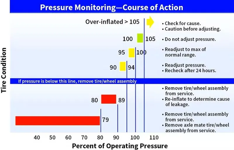
Aircraft tyres are not the same as passenger cars or truck tyres. As a result, their care and service requirements differ. The below figure compares key parameters between a passenger car tyre and two aircraft tyres of about the same dimensions and the pressure monitoring.
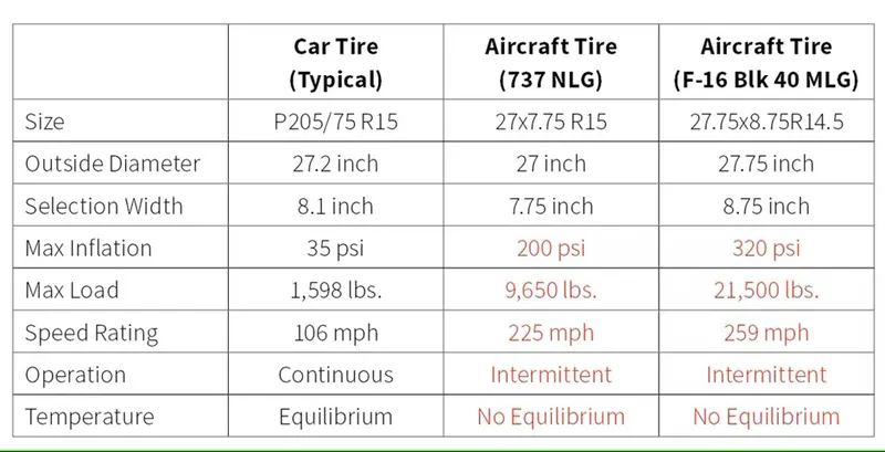
- Although the tyres are dimensionally similar, they differ significantly in rated inflation pressure, load, and speed. Additionally, the passenger car and truck tyres are able to operate continuously because they reach thermal equilibrium while aircraft tyres do not.
- An aircraft tyre that taxis continuously at rated load and 40 mph will continue to heat up until the tyre fails. The failure to reach thermal equilibrium is a consequence of the high deflections (the difference between the unloaded and loaded tyre section height) at which aircraft tyres operate. High inflation pressure and high deflection rates – 2.5 times greater than a car tyre – allow relatively small tyres to support the high loads of an aircraft.
- Because aircraft tyres operate at such high extremes of pressure, load, and speed, their care and service are critically important. The most important action an operator can take to prevent tyre-related events is to maintain proper tyre inflation pressure.
- Failure to keep aircraft tyres properly inflated can lead to very serious consequences. The most serious of these is the structural failure of the tyre.
- The most serious of these is the structural failure of the tyre. If the tyre operates underinflated or over deflected/overloaded, the nylon cords which form the structure of the tyre go in and out of compression as the tyre rotates. This weakens the cords – much like a paperclip that is bent back and forth – until eventually, the cords break. If enough cords break, the entire structure will eventually fail. The below figure shows what a compressive break in an interior ply looks like. This particular break damaged the inner liner, allowing air to migrate through the tyre to the atmosphere.
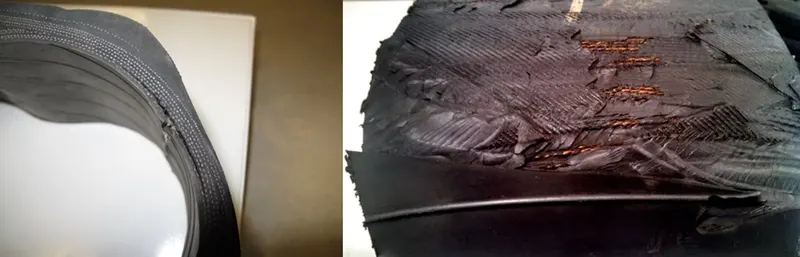
Fig:Compression break in an interior ply and Reversion of tyre
- Improper tyre pressure maintenance can have serious consequences for aircraft safety. One relatively easy way to help avoid those consequences is to check tyre pressures regularly and service them as necessary. Following these three actions is a good way to make sure you get the most value out of your tyres and contribute to the safe operation of your aircraft:
- Perform daily pressure checks with a calibrated gauge.
- Target the highest pressure recommended in the AMM (Aircraft Maintenance Manual) or POH (pilot’s operating handbook) (105 per cent of operating pressure).
- Compensate for ambient temperature changes.
Brake Forces When Landing the Aircraft: -
Aeroplanes rely on a braking system to safely land on runways. At cruising altitude, most commercial aeroplanes fly at a speed of roughly 500 to 600 mph. When landing, however, they must reduce their speed. A typical aircraft, for instance, has a landing speed of about 160 to 170 mph. And upon touching the runway, aeroplanes must quickly brake until they come to a complete stop.
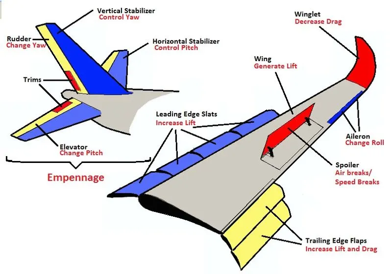
Wing Spoilers: Many aeroplanes use wing spoilers to assist with braking when landing. Not to be confused with ailerons, spoilers are extendable flaps on the ends of an aeroplane’s wings. Pilots can raise the spoilers to decelerate the aeroplane as it approaches the runway. And even while on the runway, pilots will typically leave the wing spoilers raised. Raised wing spoilers create drag, which essentially slows down the aeroplane so that it’s able to brake more quickly.
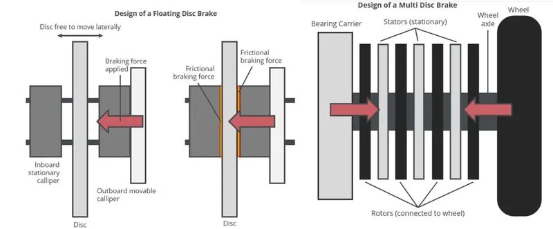
Disc Brakes: Airplane disc brakes are similar to the braking system in automobiles. They consist of a pair of callipers that, when engaged, squeeze pads against the rotors of an aeroplane’s landing gear.
Disc brakes are designed to remain static at all times. In other words, they don’t rotate with the wheels of an aeroplane’s landing gear. As the wheels turn, the disc brakes will remain static and stationary. They are a vital component of an aeroplane’s braking system because they are designed to apply pressure to the aeroplane’s wheels. Disc brakes will squeeze the wheels, thereby slowing down the speed at which they spin. In turn, this reduces the speed of the aeroplane so that it can come to a complete stop on the runway.
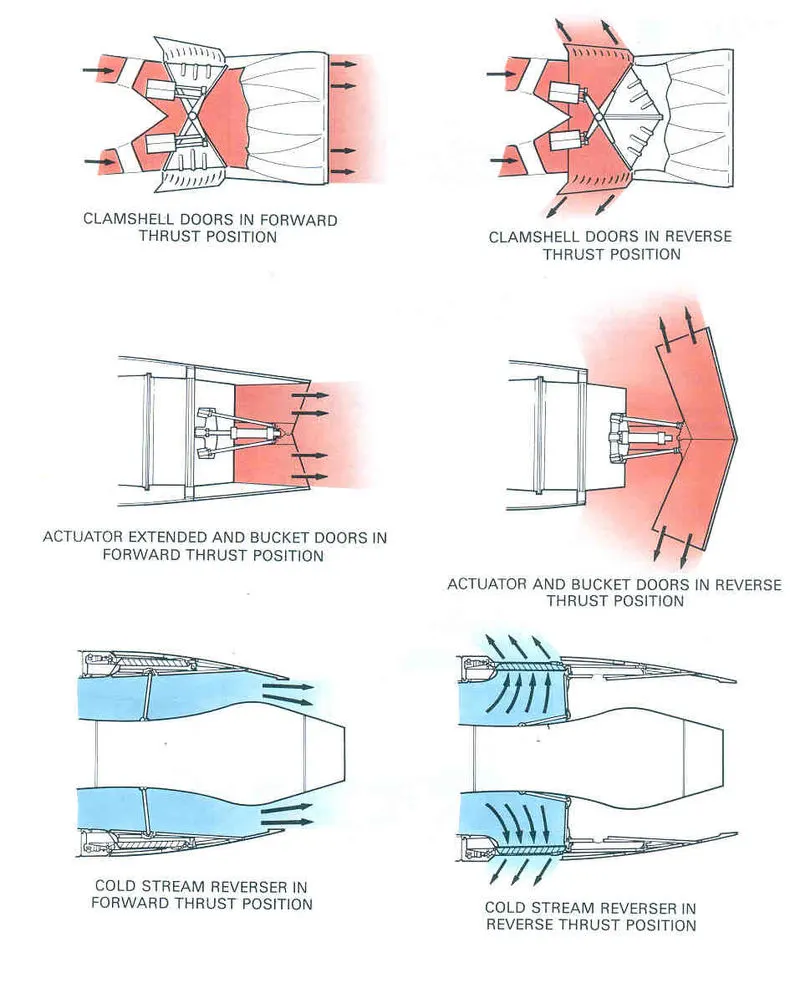
Reverse Thrust: Jet aeroplanes use reverse thrust to assist with braking during landings. Reverse thrust is a feature in jet engine aeroplanes that, as the name suggests, involves the reversal of the engines’ thrust. When flying, the thrust is projected out the rear of an aeroplane’s engines. When landing, however, pilots may use the reverse thrust feature. Reverse thrust changes the direction of the engine’s thrust. Rather than projecting out the rear, the thrust will be projected out the front. This reversal of thrust provides deceleration that allows aeroplanes to slow down more quickly when landing. The below figure shows the reverse thrust feature.
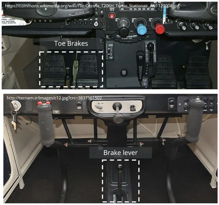
Toe-Brake Configuration: Brakes are fitted to the upper half of the rudder pedals and are actuated through the pilot applying pressure to the top of each pedal. This toe-brake configuration is widely used and allows the pilot to apply differential braking by varying the pressure applied on each toe brake.
Much smaller light sport aircraft do not make use of toe brakes, preferring to use a simpler single lever mechanism. This lever is usually situated in the cockpit centre console and applies equal braking to all main wheels when engaged. The advantages of a single braking system include reduced complexity and lower part count when compared to toe-brakes. However, differential braking is clearly not possible with a single lever mechanism.
Most aircraft are fitted with a parking brake which can be applied through a switch or lever and will keep all brakes engaged when applied.
Q6
A.With necessary assumptions, calculate the force and power required to push/pull an aircraft by a towing vehicle.
SOL: -
To propel any vehicle, we need to overcome several opposite forces acting on it. The actual forces acting on the vehicle vary from place to place and vehicle to vehicle.
To push/pull an aircraft by a towing vehicle rolling resistance force (Frr) and aerodynamic drag force (Fad)
While push/pull there won’t be a grade, so hill climbing force (Fhc) is neglected. Therefore, the total force (Fte) summation of Frr & Fad.
Frr= μrr*m*g
Fad= 0.5*ρ*A*Cd*V2
Where,
μrr= Coefficient of rolling resistance.
m= Mass of the vehicle (kg)
g= gravity (m/s2)
ρ=air density(kg/m3)
Cd= aero drag coefficient
A=frontal area or plane form area (m2)
V=velocity of the velocity(m/s)
Fte= Frr+Fad
To calculate the force and power required to push/pull an aircraft by a towing vehicle with the assumption of an aircraft Airbus A320
Mass of aircraft =78000kg
Mass of Towing vehicle= 10000kg
Gravity = 9.81
μrr= 0.05
Air density(ρ)= 1.5 kg/m3
Frontal Area(A) =442 m2
Cd(Aircraft) =0.6
Cd(Towing)=0.15
V= 6 m/s
Frr= 0.05*(10000+78000)*9.81 =43164N
Fad=0.5*1.5*442*(0.6+0.15) *62 =8950.5N
Fte= 43164+8950.5 =52114.5N
The force required to push/pull an aircraft by a towing vehicle Fte= 52114.5N
Power =Force * velocity
P=52114.5*6 =312687 watts =312.687kw
The power required to push/pull an aircraft by a towing vehicle P= 312.687kw
B.Develop the model for the calculated force and power using Simulink.
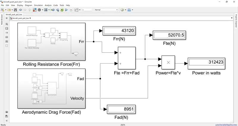
Blocks used for the model to calculate the force and power required to push/pull an aircraft by a towing vehicle
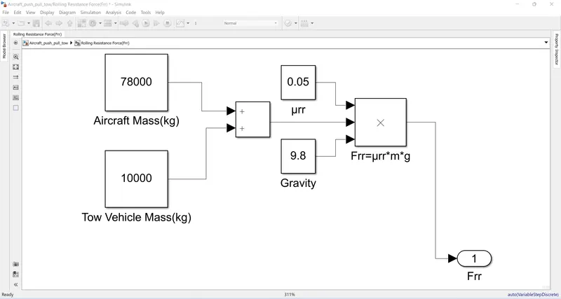
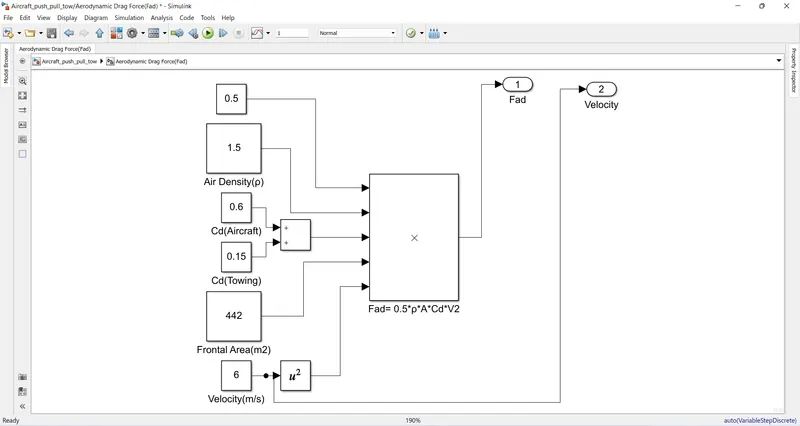
- Constant Block: To define all the assumption values such as Mass of aircraft, Mass of Towing vehicle, Gravity, μrr, Air density(ρ), Frontal Area(A), Cd (Aircraft), Cd (Towing), v(m/s).
- Add block & Product block: Used as per the mathematical requirement of the force and power equation.
- Display Block: To view the output values of forces and power
Created the subsystem for Frr and Fad for a simplified view of the model. Simulink model with output values as shown below figures
Q7
A.Design an electric powertrain with the type of motor, its power rating, and energy requirement to fulfill aircraft towing applications in Simulink. Estimate the duty cycle range to control the aircraft speed from zero to highest. Make all required assumptions. Prepare a table of assumed parameters. Draw a block diagram of the powertrain.
SOL: -
From the Q6 we have that force required for towing vehicle to propel the aircraft we need 52.11kN with the required power of 312.7kw.
Assume
Motor details
Model: H17RL 400-8
Motor Rated power =500kw
Motor Rated Voltage =400/690 v
Motor Efficiency (Em)=95%
The tyre radius =25 inches =0.635 m
Gear ratio(g) =8
Transmission Efficiency (ET)=87%
Then,
The torque required at the wheels (Tw)=force*radius
The torque required at the wheels (Tw)=52.11*0.635
=33.09kNm
The Motor Torque (Tm) =Tw/(g*ET)
=33.09/ (8*0.87) =4.75kNm
The required motor Torque = Tm/Em
=4.75/0.95=5kNm
The total power required by the motor considering all efficiencies (Pt)= P/(ET*Em)
=312.7/ (0.87*0.95) = 378.34kw
Let’s assume the operation of Towing vehicle is done for 20 minutes in hours (t)=0.3 hrs
Total Energy consumed (Er) = Pt*t =378.34*0.3 =113.50kwh
Duty Cycle (d) =Required power/Rated power
d =378.34/500 =0.756 =75.6%
Therefore, the controller will be able to provide a duty cycle ranging from 0 to 75.6% in order to control the towing speed.
Block Diagram of The Powertrain
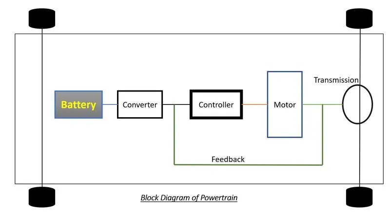
The below figure shows the block diagram for the electric power train of towing vehicle. Here you can see that all the components are connected in series the power train starts with the battery which will give power to the electric motor through the power converter. The electric motor is further connected with the motor controller to control the output as per the driver’s requirement and finally, the motor controller is connected to the transmission system which will transmit the power to the wheels.
Simulink Diagram of powertrain:
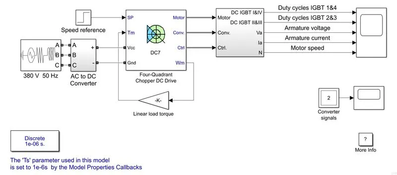
The above model represents the simple powertrain model for aircraft on the runway. In general, the power train consists of the 200 HP DC motor that is separately excited with a constant 150 V DC field voltage source. The armature voltage is provided by an IGBT converter controlled by two PI regulators. The converter is fed by a 515 V DC bus obtained by rectification of a 380 V AC 50 Hz voltage source. In order to limit the DC bus voltage during dynamic braking mode, a braking chopper has been added between the diode rectifier and the DC7 block.
This model consists of a dc drive (DC) The main purpose of the dc drive is it consists of the controller also. The DC7 model is the reference for the powertrain for the aircraft on the runway.
Output:
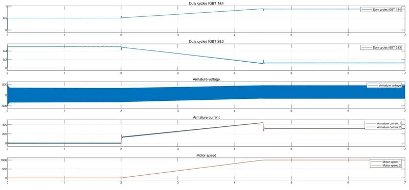
The plot consists of the duty cycles of the controller IGBT switches, Armature voltage of the motor, armature current of the motor, and motor speed. We can see that the duty cycles of IGBT 1&4 varied and reached 90% then the motor speed also varied and reached its rated speed
B.Also, Design the parameters in an excel sheet.
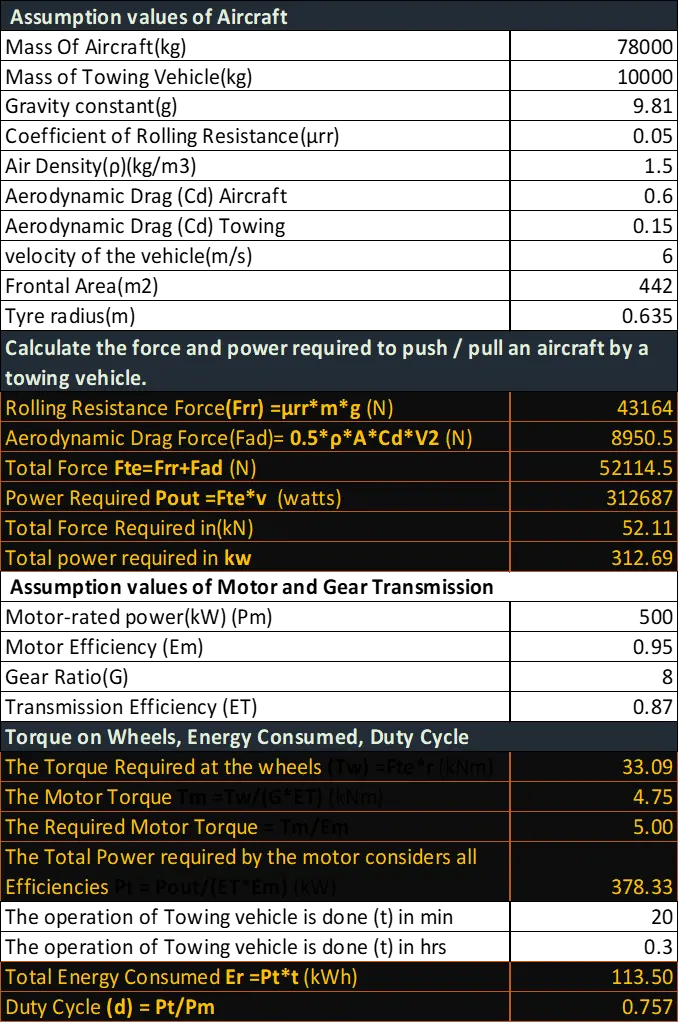
The excel sheet is attached.