Week-11 Challenge: Braking
Q1
For a defined driving cycle, calculate the energy required for braking.
Definition of Brake: A brake is one of the most important controls of the vehicle. This is a combination of some interactive parts. It absorbs energy from the moving part and slows down the vehicle with the help of friction. The function of the brake system is to stop the vehicle within the smallest possible distance and hence this is done by converting the kinetic energy of the vehicle into the heat energy which is dissipated into the atmosphere.
The brake system in an automobile can be classified into the following categories:
- Mechanical Brake
- Disc Brake
- Hydraulic Brake
- Power-assisted Brake
- Air Brake
- Electric and
- Hand brake System
Mechanical Brake: The mechanical brake is used in small power automobiles like scooters, motorcycles, and some modern vehicles. As the brake pedal is pressed cam rotates, which pushes the brake shoes outwards, and hence brake lining provided on the outer surface of the shoes rubs against rotating the drum and hence slow down or stops the vehicle because the drum is connected to the wheels.
Disc Brake: The disc brake is used in motor vehicles and cars, etc. When the pedal is pressed piston pushes the pad by the pressure of the hydraulic fluid. These friction pads rub against the rotating disc connected to the wheels of the vehicle and thus braking takes place. And as the pedal is released friction pad returns to its original position as the pressure of hydraulic fluid reduces.
Hydraulic Brake: Hydraulic brake works on the principle which is based on Pascal's principle, which states that "confined liquid transmits pressure without loss in all direction". When the brake pedal is pressed, fluid from the master cylinder enters the wheel cylinders through pipelines by the force of the piston. Due to the liquid force, the piston of the wheel cylinder pushes outward which pushes the shoes outward. Lining rub against the drum and hence braking takes place. Now when the pedal is released, the piston of the master cylinder moves backward and fluid from the wheel cylinder moves to the master cylinder through the check valve. This type is commonly used in all cars etc.
Power-assisted or Vacuum brake: As the brake pedal is pressed, the fluid pressure causes the upper valve of a control unit to open and lower the valve to close. Thus left the side of the servo cylinder piston is exposed to the atmosphere and a vacuum act on the right side, which causes the braking effort. Braking takes place by suction from the engine inlet manifold.
Air Brake: This type of air brake system is commonly used in heavy vehicles such as buses, trucks, etc. In this also when the brake pedal is pressed, air to atmosphere enters the compressor through the air filter to the reservoir through unloader value. From the unloader valve air enter the brake chamber through the brake valve. A brake valve is fitted in order to control the intensity of braking. Thus, braking takes place. When the pedal is pressed shoes return to their original position through the spring force.
Electrical Brake System: The principle of working this type of brake is to utilize the electromagnetic force on the brake shoes. It consists of an electromagnet and armature disc. An electromagnet is mounted on the backplate and an armature disc is fed to the drum. For work, an electric current for the battery is utilized to energize the electromagnet which actuates the cams that expands the shoes. Thus, braking the wheel.
Hand brake System: Hand brakes or the parking brakes operate independently of the foot brakes. These are used for parking on slopes or while waiting at traffic lights, where the handbrake function is mainly to minimize accidents. This brake is applied after the foot brake is applied.
Apart from the hydraulic braking system, all cars have a mechanical handbrake acting on two wheels usually the rear ones. The handbrake gives limited braking if the hydraulic system fails completely, but its main purpose is as a parking brake.
The braking energy required for a vehicle can be explained as the power required for acceleration is equal to the power required for deceleration to stop the vehicle at the possible smallest distance.
Therefore, Braking Energy = (1/2) *m*(vi-vf)2
Where m= mass of the vehicle
vi =Initial Velocity of braking
vf =Final Velocity of braking
By using a defined drive cycle, we will calculate the braking energy of the drive cycle. Here we have considered NEDC.
New European Driving Cycle (NEDC): - The New European Driving Cycle (NEDC) is a driving cycle, last updated in 1997, designed to assess the emission levels of car engines and fuel economy in passenger cars (which excludes light trucks and commercial vehicles). It is also referred to as the MVEG cycle (Motor Vehicle Emissions Group). The NEDC, which is supposed to represent the typical usage of a car in Europe, is repeatedly criticized for delivering economic figures which are unachievable in reality. It consists of four repeated ECE-15 urban driving cycles (UDC) and one Extra-Urban driving cycle (EUDC).
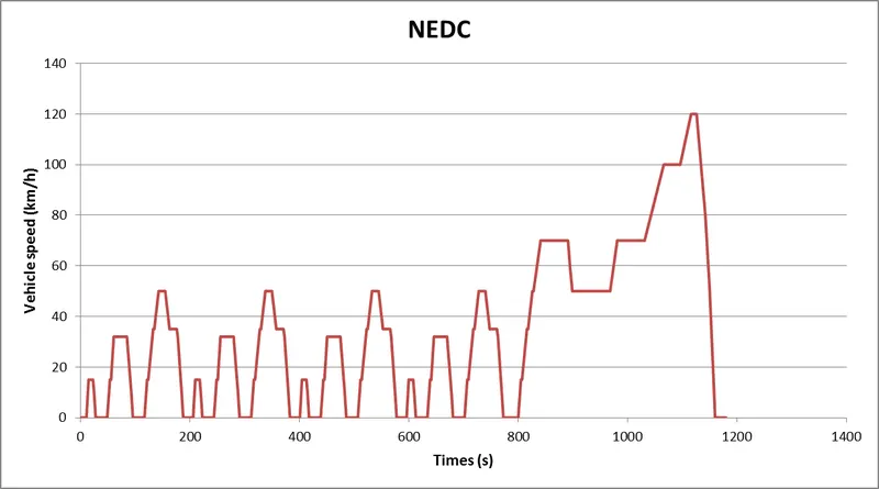
By using the Grabit tool in MATLAB to extract the data from a published graph and stored the values text file and same transferred to the excel file. Modified the data of time 1200 sec to 209 sec.
We calculate the braking energy of the driving cycle by using the MATLAB script as given below.
Import the drive cycle data to the MATLAB workspace in the Numeric Matrix Output type.
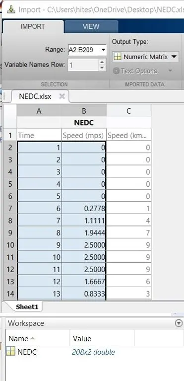
MATLAB Script:
mass=1000;%mass of the vehicle
t=NEDC(:,1);%time period
v=NEDC(:,2);%velocity data in m/s
for i=1:(length(NEDC)-1)
if v(i)>v(i+1)
BE(i)=0.5*mass*(v(i)-v(i+1))^2;%BE=Braking Energy
end
end
fprintf('Total Brake Energy is %d',sum(BE))%fprintf will display the value in command window
fprintf('Average Brake Energy is %d',mean(BE))
subplot(2,1,1)%to plot multiple graphs in same window
plot(t,v,'linewidth',3,'color','r')
xlabel('Time(s)')
ylabel('Velocity(m/s)')
title('NEDC')
subplot(2,1,2)
plot(BE,'linewidth',3,'color','g')
xlabel('Time(s)')
ylabel('Braking Energy')
Results:
We will get the total brake energy and average brake energy of the defined cycle in the command window as shown below.

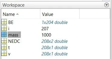
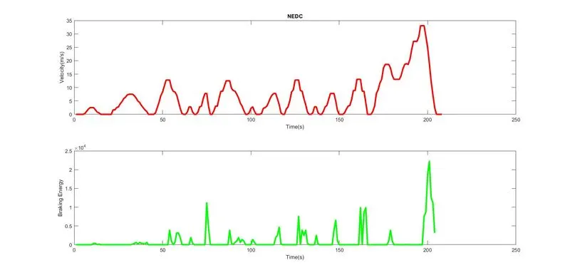
The above plots show the drive cycle accordingly, the brake energy applied as per the drive cycle.
Q2.
Why electric motor can’t develop braking torque at a high speed similar to starting?
Ans: -
In the electric vehicle the motive that gets the energy back to the battery, it will be possible if the regenerative braking power requirement is more than the charging limit of the battery or more than the regenerative capacity of the machine, so we must apply mechanical brakes as well. The combination of these two is applied.
By using the speed-torque characteristics of an electric motor used in EV application as shown below.
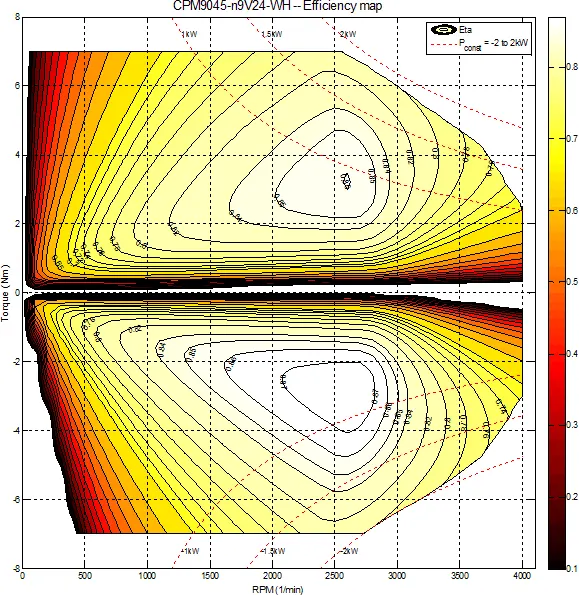
The above plot explains the 1st & 2nd quadrant’s speed-torque characteristics, here the speed is in the +ve direction and torque in both the +ve & -ve axis.
The characteristics of Q1 & Q2 were mirror image which is almost similar. Usually, we can say that an electric vehicle can achieve 0 to 100kmph in 10sec, so we have an expectation an electric car can perform this acceleration or which can meet this acceleration. From the above characteristics from 0 speed of the motor to 100kmph and at 100kmph, we have 2300 rpm.
Now we need to check with the EV motor that 100kmph is now braking to 0 speed in again 10sec. from the above characteristics, we can see the value of torque from low-speed characteristics. During low speed the torque produced by the motor is almost constant, therefore here higher acceleration power is possible.
Now we reached the point where the vehicle speed is 100kmph and we can see that point is not in the constant torque region it is in the constant power region.
So, at this particular point, we must understand that it is easier for the motor to reach from 0 to 100kmph and now it comes to the braking part where the torque is -ve by replicating the same point in Q2. Now at this particular point, the braking torque which the motor can develop that particular braking torque is around -4Nm, compare to the peak torque of around 7Nm.
So, peak acceleration torque and peak deceleration torque are not equal for electric vehicle motors.
Acceleration is usually higher at low speed you will get higher torque, but at the high speed, the value of torque is lower.
So, we can’t say that the motor which is producing around 7Nm of acceleration torque can also produce -7Nm of braking torque. So, because we are operating the motor in the field weakening region or we are operating above the base speed (no-load speed) we must know that the torque value is compromised or torque value is lower.
Therefore, regenerative braking cannot happen so effectively that we can get all the power back to the battery. This we can say that one of the motor’s limitations.
How electric and mechanical brakes are coordinated?
The Total brake force is a combination of a Regenerative brake and a mechanical brake. The sharing percentage of electrical bake & mechanical brake is dependent on choosing. The brake force can also be the combination of front axial & rear axial, usually, the front-wheel-drive vehicle has a higher braking force. So, it is not advisable to increase the rear braking force.
The percentage of sharing both front and rear should be considered by the safety maintained and driving direction not compromised.
By the coordination of the electric and mechanical brakes, we have two brake control strategies
- Series brake control strategy: Here we apply the mechanical brakes and electric brakes one after another, which means here we can apply either a regenerative brake or a mechanical brake.
It is further classified into 2 on basis of comfort and energy saving.
- More comfort braking systems with less energy saving.
- More energy saving with less comfort braking.
- Parallel brake control strategy: Here we apply both mechanical brakes and electric brakes simultaneously at a time.
EV is able to be used to brake regeneratively, so braking energy can be recycled. The braking stability of electric vehicles with electro-hydraulic braking systems can be influenced by braking force distribution between hydraulic braking force and regenerative force.
The coordination of both brake systems can be explained by another control strategy which is known as Electric Driven Intelligent Brake (EDIB).
Electric Driven Intelligent Brake: It is a type of parallel braking as shown in the below picture.
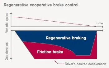
We can see that the frictional brake and the regenerative brake are used simultaneously at higher speeds of the vehicle. At low speed, the torque of the motor is high so the regenerative brake has a higher sharing percentage than the frictional brake.
Working
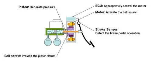
Electric Driven Intelligent Braking System, the braking force is provided with the help of an ECU-controlled motor and ball screw arrangement. This means that no direct load on the engine while applying brakes. This means that a motor-operated the brake for providing the braking energy. A more controlled and uniform braking force is applied since it is ECU controlled, this helps to recover braking losses when a regenerative braking system is used.
Q3.
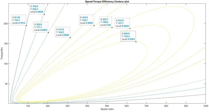
Make a MATLAB program that plots the contour of given motor speed, torque, and efficiency values. Attach the code as a .m file and attach a screenshot of all the plots.
ANS: -
Permanent magnet DC motor has various types of loss happening inside the armature and the stator winding which were given below.
Copper Loss: The copper loss is nothing but I2R loss, where R is the resistance of armature. We know that Torque ‘T’ is proportional to Current ‘I’ then the copper loss can be considered as the constant ‘Kc’ time square of the Torque.
Pcu = I2R =KcT2
Where Kc is taking care of resistance of brushes coil and magnetic flux & its effect.
Iron Loss: Iron loss is nothing but magnetic loss which is
PI =Ki*ω
ω= angular speed of the motor
Ki is based on the magnetic field effect.
In a permanent magnet motor, we have a constant magnetic field so, these iron losses will be based on the value of Ki then the Iron losses will change according to speed because, at various speeds, the motor will have a different value of back emf. Therefore, it is going to affect the Iron loss.
Windage Loss: This is also known as mechanical loss or friction loss of the motor.
Pw= Kw*ω3
Kw is based on the size and shape of the motor and the amount of windage loss is going to experience.
Constant Loss: These losses are constant irrespective of the load condition. It is denoted as C.
The total power loss PTotal Loss = KcT2 + Ki*ω + Kw*ω3 + C
Kc, Ki, and Kw are going to affect the total loss and with certain accuracy, almost all types of motor can be mathematically modeled as per the loss equation mentioned above.
MATLAB Program That Plots the Contour of Given Motor Speed, Torque, And Efficiency Values
x=linspace(1,1000);%speed
y=linspace(1,250);%Torque
kc=0.2;%Copper loss constant
ki=0.008;%Iron loss constant
kw=0.00001;%Windage loss constant
ConL=20;%Constant Loss
[X, Y]=meshgrid(x,y);%Converting into 2D
Pout=(X.*Y);%Output Power =Speed*torque
B=(Y.^2)*kc;%Copper Loss
C=X*ki;%Iron Loss
D=(X.^3)*kw;%Windage Loss
Pin=Pout+B+C+D+ConL;%Input Power
Z= Pout./Pin;%Efficiency
V=[0.70,0.80,0.85,0.90,0.91,0.92,0.925,0.93];%Efficiency plotting ranges
box off
grid off
contour(X,Y,Z,V)
xlabel('Speed,rad/s')
ylabel('Torque,Nm')
title('Speed-Torque Efficiency Contour plot')
Speed-Torque Efficiency Contour plot