Project-1: Modelling an electric Car with Li-ion battery
PROJECT-1: MODELLING AN ELECTRIC CAR WITH LI-ION BATTERY
Aim: -
- Create a MATLAB model of an electric car that uses a lithium-ion battery and a suitable motor by using the PI controller.
- To check the performance of the system configuration, model parameters on areas like – Motor speed, Motor Torque, State of Charge, Battery voltage & current.
- To check whether the vehicle speed track at the given reference speed.
Introduction: -
An electric vehicle is a vehicle, which uses one or more electric motors for propulsion. Depending on the type of vehicle motion may be provided by a rotary motor or by a linear motor (in the tracked vehicle). The electricity stored in battery-powered by electric motor & battery can be charged by plugging it into the grid, like our phone.
According to the degree of electricity used, an electric vehicle is divided into 3 categories-BEV, PHEV & HEV.
Battery Electric Vehicles (BEV)
BEVs are fully electric vehicles with rechargeable batteries with no engine. It stares power in a battery pack & this power is used to run the vehicle & other peripherals BEVs are charged by electricity from an external source BEVS don't emit any hazardous emissions. Some most famous examples of these types of cars are BMW 13, and Tesla Model, 3. Kia Soul Toyota Rav4 etc.
Hybrid Electric Vehicle (HEVs)
HEVs are powered with both gasoline & electricity. The battery can be charged with regenerative power only. The motor supplies power from starting, the engine takes care of high speed & heavy load. Controller used to ensure the best economy, HEVs are Honda Civic Hybrid, Toyota Prius Hybrid, and Toyota Camry Hybrid.
Plug-In Hybrid Electric Vehicles (PHEV)
These types of vehicles are propelled by motor and gasoline engine Battery is charged with regenerative braking & it can be charged with external source PHEVS can go from 10-40 miles before the assistance of engine Examples PHEVs-Chevy Volt. Audi A3 E-Tron BMW i8. Toyota Prius etc
System Level Configuration –
Electric Vehicle model -
- The electric vehicle model is represented by using MATLAB/Simulink. This model is a complete representation of an electric vehicle that is built using a Powertrain Block set.
- This model has a vehicle dynamics & electrical system; the vehicle dynamics contains s subsystem related to the vehicle body & tires whereas the electrical system contains a subsystem related to the motor & battery pack.
- This subsystem contains various other components parameterizing and configuring with each other explained in detail.
The Block diagram of the model is shown below
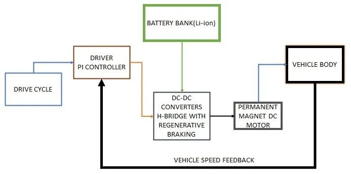
Explanation:
The drive cycle is the input signal that will provide the data of acceleration and deceleration of the vehicle to the driver or controller (PI controller) will evaluate and provide the signals to the Inverter (H-bridge) in the form of a pulse. The inverter is connected to the Battery (Li-ion) bank which will provide a power supply to the motor according to the signals received from the controller. The motor which is connected to the wheels through the differentials will drive the vehicle. The Vehicle velocity feedback is given to the controller which will calculate the error and provide the rectified signals to the Inverter to improve the performance of the vehicle.
MODELLING OF Electric Vehicle
Vehicle Dynamics/ Vehicle Body:
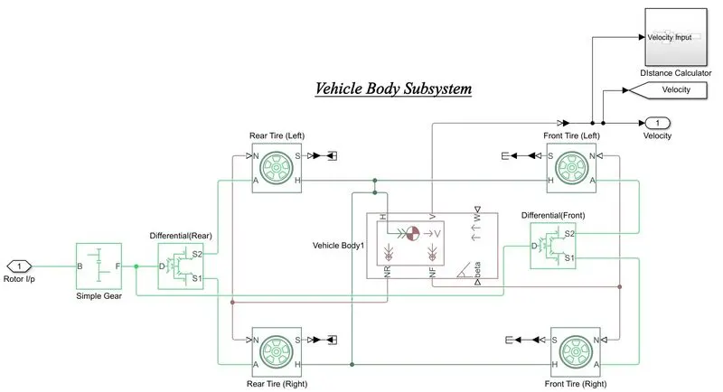
- To design the vehicle, we have taken 4 tires (Tire Magic Formula blocks) which can be arranged as 2 in front and 2 in the rear position of the vehicle. All four tires will be connected to the Vehicle body Block which will perform the mechanical operation of the vehicle.
- N-port of rear tires connected to the NR-port of the body and N-port of front tires connected to the NF-port of the body. H-Ports of all tires were connected to the H-port of the body.
- Axle ports of the front tires are connected to the simple gear through the differential as well as Axle ports of the rear tires are connected to the simple gear through the differential.
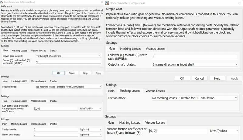
- Simple gear will get the input as a mechanical rotation of the motor shaft. The gear ratio of the Differential and the simple gear same value should be maintained.
- Here we are not considering the slip of the tires so we have connected them to the terminators through the PS-Simulink.
- The v-port of the body is the velocity output of the vehicle. The same signal is given as feedback to the controller through the PS-Simulink by changing the signal unit from 1 to km/hr.
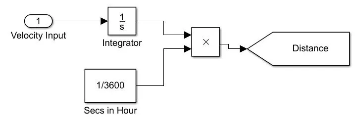
- The distance traveled by the vehicle is calculated by the Distance subsystem as shown below.
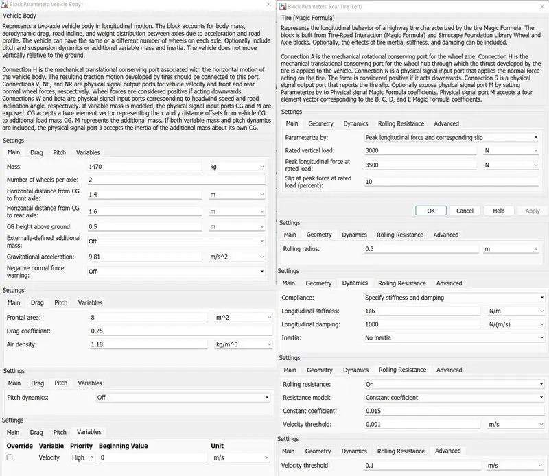
The Parameterizing of the Tires, Simple gear, Differential, and the vehicle body shown below
Electric Motor:
An electric car used electric power to generate the torque and power output to propel the car forward and enable motion in the car. Traditionally, this was done by the internal combustion engine which required fuel to have enough energy to rotate the wheels of the car and overcome the resistive forces to the motion. So, the function of the electric motor is similar but the application is completely different in terms of everything.
A permanent Synchronous Magnet Motor is a magnet either embedded into the rotor or placed on the surface of the rotor. A magnetic field is generated and the rotation causes the vehicle to move. In this case, however, the speed of the rotating magnetic field is similar to that of the speed of the rotor, which is why it is known as a synchronous motor. Depending on the placement of the magnets, these are divided into Interior Permanent Magnet Motor or Surface Permanent Magnet Motor. These are the two most frequently used electric motors in cars due to their robustness, high efficiency, power, and relatively simple technology.
The modeling of the Motor Subsystem as shown below
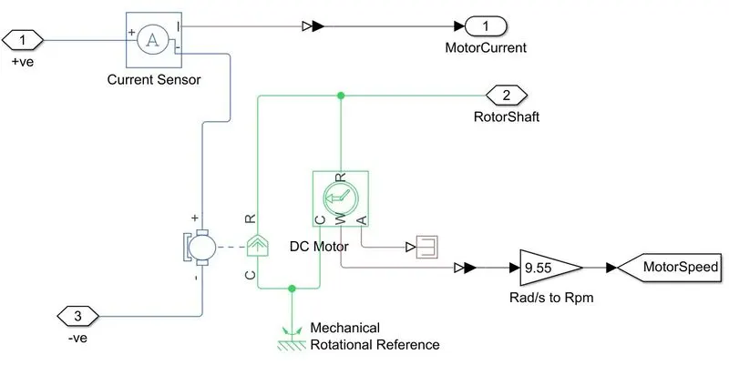
The electric power input to the motor is provided by the inverter from the Battery and the output mechanical rotation of the rotor shaft is given to the gears of the vehicle subsystem. The motion sensor is used to measure the speed of the motor and did the conversion from rad/sec to RPM.
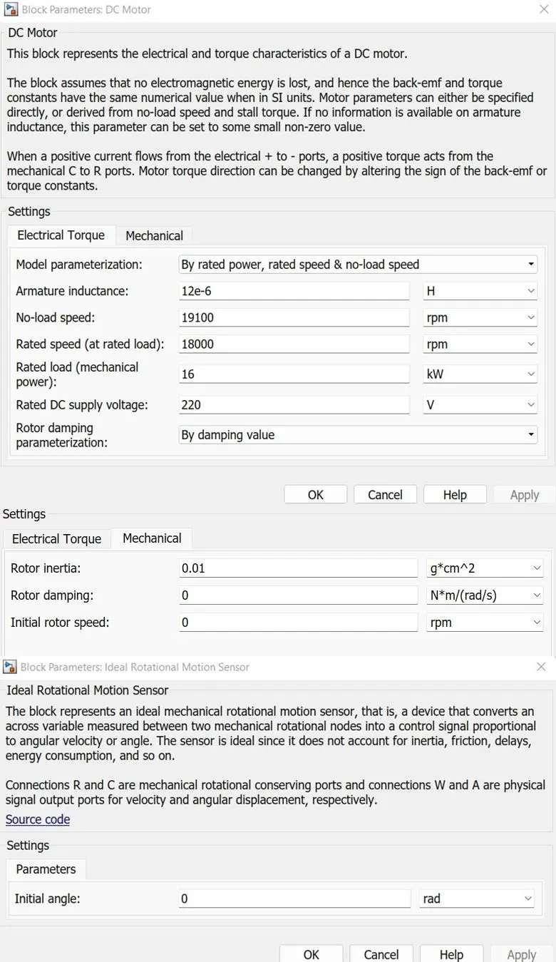
The Parameterization of Motor as shown below
INVERTER/H-bridge:
Within an electric drivetrain, the inverter controls the electric motor. This is a key component in the car as, similar to the Engine Management System (EMS) of combustion vehicles, it determines driving behavior. Regardless of whether the motor is synchronous, asynchronous, or brushless DC, the inverter always functions in a similar way and is controlled by an integrated PCB, which should be designed to minimize switching losses and maximize thermal efficiency. Not only does the inverter drive the electric motor but, it also captures energy released through regenerative braking and feeds this back to the battery. As a result, the range of the vehicle is directly related to the efficiency of the traction inverter.
The modeling of the H-Bridge with Regenerative braking Subsystem is shown below
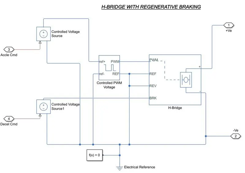
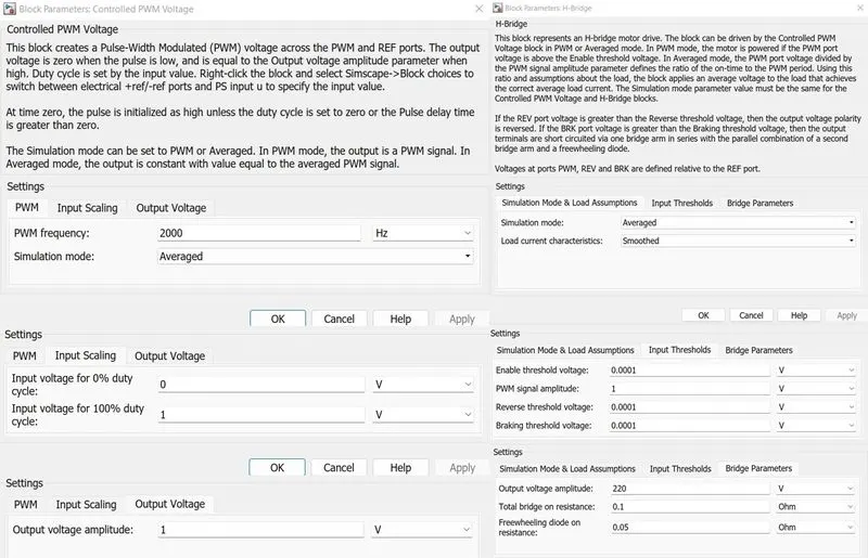
The H-Bridge will get the signals from the driver, the acceleration command is given through the controlled PWM block which will send the signals as 0&1 to the INV. All the electrical connections were shown in the above picture.
The Parameterization of PWM and H-Bridge as shown below
The simulation mode of both blocks was selected as the Average Mode for the fast simulation process.
Battery:
The battery is the energy source of any system. The reason behind the popularity of these cell batteries in EVs is low discharge rates compared to capacitor banks are also less expensive & required less maintenance and constant monitoring than Hydrogen cells. Lithium-Ion battery eliminates all these disadvantages and requires fewer operational costs.
The lithium-Ion battery has an average life span of more than 8 years. Safety reduces the risk of accidents by eliminating exposure to flammable fuels. Able to withstand even in the high temp. without high temperatures.
Also, Lithium-Ion batteries provide significant environmental benefits over fossil fuels. With the steady increase in electric vehicles, we can see the immediate impact on the reduction in carbon emissions.
Hence knowing all such advantages of Lithium-Ion Manufacturers prefer using lithium cells as their main source of energy.
Formula to calculate SoC –
SOC (t) = SOC (t-1) + Bat.dt
Where,
SOC(t) = State of Charge at time (t).
SOC(t-1) = Initial State of Charge.
I = Charge/Discharge current (A).
t = Time (H).
Bat = Battery Capacity.
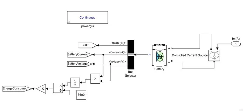
The Parameterization of the Battery Bank as shown below
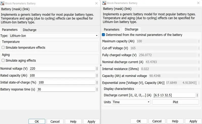
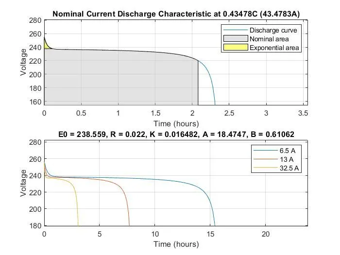
The Discharge characteristics of the bank is shown below
Drive Controller:
The Simulink provides the programmed drive controller such as Longitudinal Driver or Lateral driver, but in this model, we have designed the driver by using the PI controller.
PID Controller (2DOF)
The PID Controller (2DOF) block implements a two-degree-of-freedom PID controller (PID, PI, or PD). The block is identical to the Discrete PID Controller (2DOF) block with the Time domain parameter set to Continuous-time.

The block generates an output signal based on the difference between a reference signal and a measured system output. The block computes a weighted difference signal for the proportional and derivative actions according to the setpoint weights (b and c) that you specify. The block output is the sum of the proportional, integral, and derivative actions on the respective difference signals, where each action is weighted according to the gain parameters P, I, and D. A first-order pole filters the derivative action.
The block supports several controller types and structures. Configurable options in the block include:
- Controller type (PID, PI, or PD) — See the Controller parameter.
- Controller form (Parallel or Ideal) — See the Form parameter.
- Time domain (continuous or discrete) — See the Time domain parameter.
- Initial conditions and reset trigger — See the Source and External reset parameters.
- Output saturation limits and built-in anti-windup mechanism — See the Limit output parameter.
- Signal tracking for bumpless control transfer and multiloop control — See the Enable tracking mode parameter.
As you change these options, the internal structure of the block changes by activating different variant subsystems.
Saturation
Limit input signal to the upper and lower saturation values.

The Saturation block produces an output signal that is the value of the input signal bounded to the upper and lower saturation values. The upper and lower limits are specified by the parameters Upper limit and Lower limit.
|
Input |
Output |
|
Lower limit ≤ Input value ≤ Upper limit |
Input value |
|
Input value < Lower limit |
Lower limit |
|
Input value > Upper limit |
Upper limit |
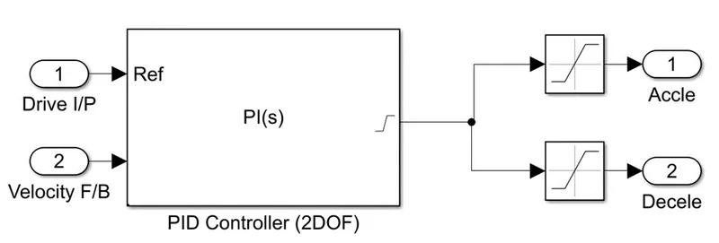
The Drive cycle input and the vehicle velocity feedback are given as inputs to the PI controller and the output is given to the saturation blocks of acceleration and deceleration which are fed to the Inverter(H-bridge)
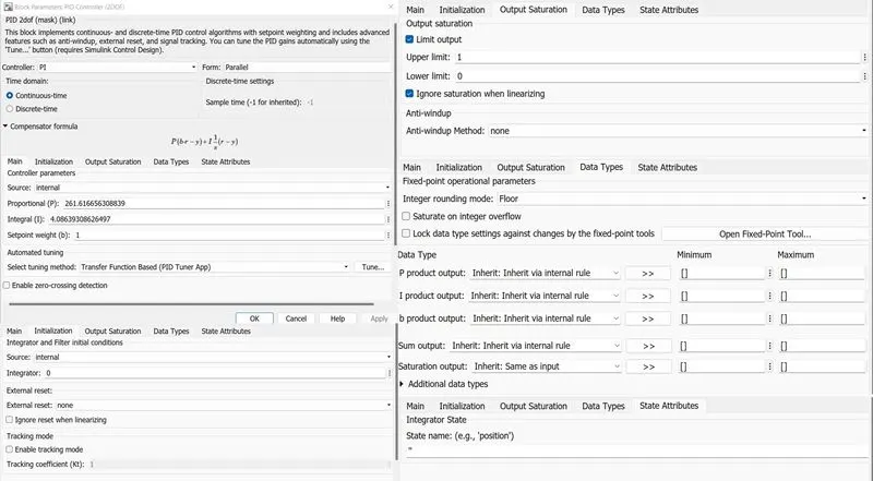
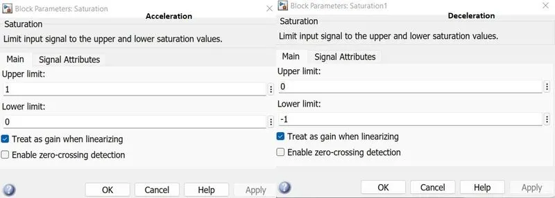
The Parameters of the PI controller were tuned to get a fine response, and the parametrization of the PI controller and the Saturation blocks were shown below.
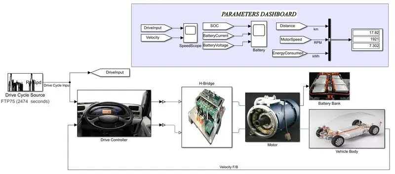
Electric Car with Li-Ion Battery, Suitable Motor, and PI Controller Simulink Model
Results:
Drive Input: FTP75 Drive Cycle
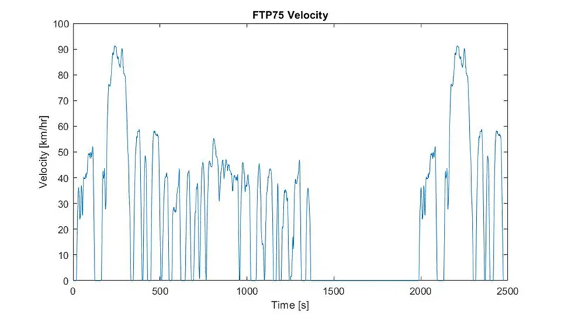
Duration: 2474 s
Distance traveled: 17.77 km
Average speed: 34.12 km/h
Maximum speed: 91.25 km/h
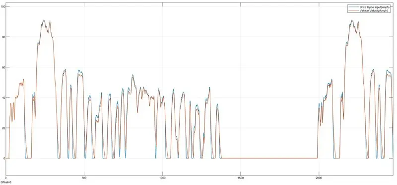
From the above Plot of Drive input Vs Vehicle Velocity, we can see that with tunned PI controller the vehicle velocity achieved and followed the reference signal with few deviations while the input signal gets decelerating with a max deviation of 13 sec at one instant of the entire run time.
In the total run time of the simulation, the Battery trends are as follows
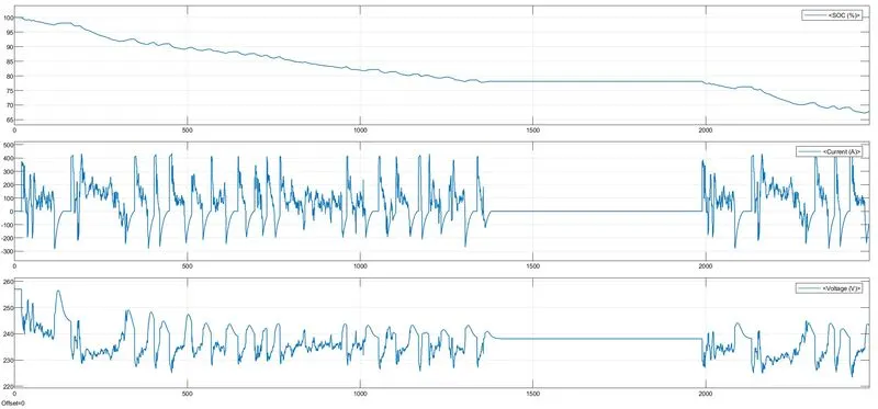
While the start of the simulation the SOC of the battery is considered 100% at the end of the simulation SOC of the battery is 68%. In the above plot, we can the trends of battery voltage and the current as well we can see that the current in the -ve axis, means regenerative braking, while the vehicle is deceleration the motor will act as the generator which will generate the power and injected to the Battery through the Inverter.
The total distance travelled:17.82km and the total energy consumed: 7.302kWh
Consider that the vehicle runs until battery SOC reaches 0%, Let us check the Battery Trends as shown below
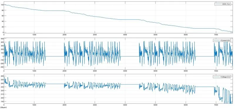
From the above plot when the SOC of the Battery reaches 20% the degradation of Voltage happened which will affect the battery life span not permissible to operate also.
With the given drive cycle by consuming Battery SOC fully the vehicle traveled a distance of 54.43 km with a running time of 7550secs and total energy consumed: 21.38kWh