Week -2
Q1.
A chime doorbell uses a specialized sort of electromagnet called a solenoid. A solenoid is just an electromagnet where the coiled wire surrounds a metal piston. The piston contains magnetically conductive metal, so it can be moved backward or forward by the electromagnetic field.
The given diagram is similar to below
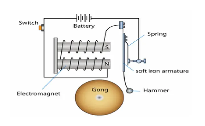
we can see that it is having a battery supply source, switch, solenoid, spring, and soft iron armature with a hammer and gong that the hammer can hit it. A solenoid plunger is the moving part of a solenoid that transfers linear motion from the solenoid to the component that it is designed to operate.
To the Simulink model with the reference to the given diagram, we need the following blocks.
Battery: This block model is a battery. If you select Infinite for the Battery charge capacity parameter, the block models the battery as a series of internal resistance and a constant voltage source.
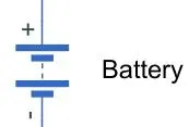
The +ve of the battery is given to the switch and -ve given to the electrical reference.
Switch: The block represents a switch controlled by an external physical signal. If the external physical signal PS is greater than the threshold, then the switch is closed, otherwise, the switch is open. The switch is connected to the +ve of the solenoid.
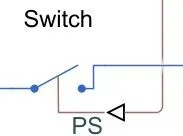
Since it is controlled by the external signal, we will give pulses from the pulse generator.
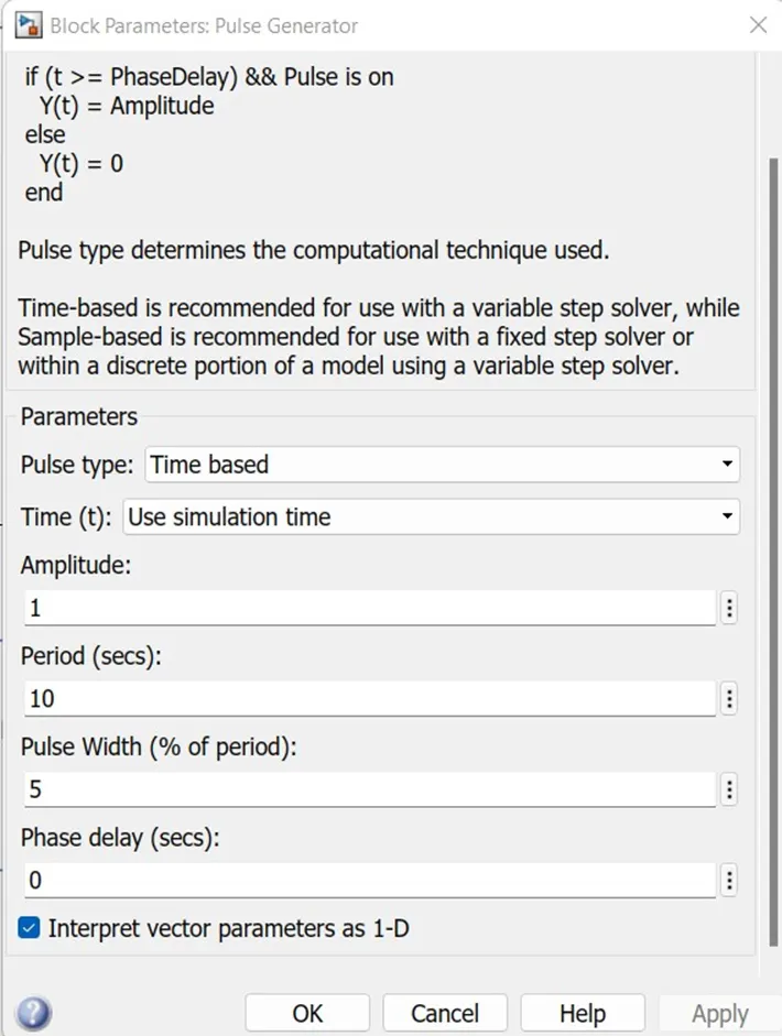
Pulse Generator: The Pulse Generator block generates square wave pulses at regular intervals. The block waveform parameters, Amplitude, Pulse Width, Period, and Phase delay, determine the shape of the output waveform.
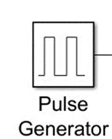
To connect both switch and pulse generator we need Simulink to PS block because the switch is controlled by an external physical signal and the pulse generator will provide the simulated signal.
Simulink-PS Converter: The Simulink-PS Converter block converts the input Simulink® signal into a physical signal. Use this block to connect Simulink sources or other Simulink blocks to the inputs of a Physical Network diagram.
Solenoid: The Solenoid block represents the electrical characteristics and generated force for the solenoid in the following figure:
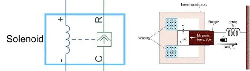
The return spring is optional. To remove the effects of this spring from the model, set the Spring constant parameter to 0.
-ve of the solenoid given to the electrical reference. The R port of the solenoid is connected to the R port of the translation motion sensor.
Ideal Translational Motion Sensor: The Ideal Translational Motion Sensor block represents a device that converts an across variable measured between two mechanical translational nodes into a control signal proportional to velocity or position. You can specify the initial position (offset) as a block parameter.
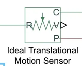
The sensor is ideal since it does not account for inertia, friction, delays, energy consumption, and so on.
The C port of the solenoid and motion sensor both were connected to mechanical reference. Position port was given to the solver configuration.
Mechanical Translational Reference: The Mechanical Translational Reference block represents a reference point, or frame, for all mechanical translational ports. All translational ports that are rigidly clamped to the frame (ground) must be connected to a Mechanical Translational Reference block.

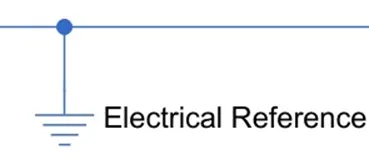
Electrical Reference: The Electrical Reference block represents an electrical ground. Electrical conserving ports of all the blocks that are directly connected to the ground must be connected to an Electrical Reference block. A model with electrical elements must contain at least one Electrical Reference block.
Solver configuration: Each physical network represented by a connected Simscape™ block diagram requires solver settings information for simulation. The Solver Configuration block specifies the solver parameters that your model needs before you can begin the simulation
Each topologically distinct Simscape block diagram requires exactly one Solver Configuration block to be connected to it.
Scope: The Scope is optimized for general time-domain simulation.

A total two number of scopes were used to view the pulses generated by the pulse generator and view the position of the bell.
Simulink Model:
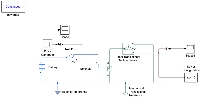
Explanation:
- Battery supply positive connected to the switch and the negative connected to the electrical reference.
- Another end to the switch is connected to the positive port of the solenoid and the negative port of the solenoid given to the electrical reference.
- To close the circuit, the switch needs to be operated, so that connected the pulse generator to the switch through the Simulink to PS. The pulse generator will generate the ON/OFF pulse so that the switch gets close & open.
- Another section of the solenoid block which mechanical operation. The R port of the solenoid (Mechanical translational conserving port) is given to the R port of the Translation Motion sensor (Rod, sensor’s positive port).
- The C port of both solenoid block and Translation motion sensor is connected to the Mechanical translation reference.
- In solenoid block the ports C& R represent the fixed-point & plunger respectively. In Translation motion sensors ‘V’ & ‘P’ represents were velocity & position of the plunger.
- To view the output which means the position of the plunger when the switch was closed will connect the P port of the Translation motion sensor to the scope block through the PS-Simulink block. As well as to check the generated pulses we have connected the scope to the Pulse generator.
- Let us check the output with the default parameters of the blocks Pulse width: 5%, period =10 secs, and run the simulation period for 10 sec
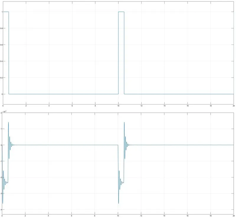
- Let us change the parameters of the pulse generator Pulse width: 50%, period =5 secs, and run the simulation period for 20 sec
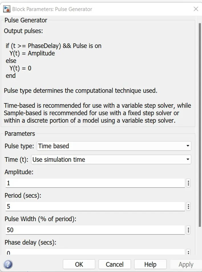
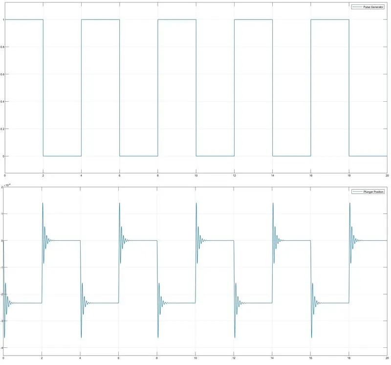
- From the above graph, we can see that the phase delay was 2. This means at initially the pulse amplitude was 1 and at the end of the 2sec the amplitude becomes ‘0’and t=2 to 4 amplitude stays at ‘0’. At t=4 sec again amplitude raise to 1 and the same cycle is continued. Here the time period between the amplitude rises and falls was t=2 sec.
- When the pulses with the time delay between rising and falling t=2 sec are given to the switch then accordingly the operation of the switch will also be the same the switch is closed for 2 seconds and then released.
- When the amplitude is ‘1’ the switch will close the circuit and the current flow through the switch and pass into the solenoid. The electromagnet is powered and generates a magnetic field that attracts the iron strip towards it. The striker strikes the bell. When the striking arm strikes the bell, the amplitude becomes to ‘0’ then the contact is broken and the current stops flowing through the circuit.
- From the above graph also, we can observe that from the plunger position plot that the plunger vibrations were recorded according to the pulse generator plot by maintaining the time delay t = 2sec.
- Till now we have checked by changing the input signal of the model, let’s check by altering if the mechanical parameters were changed, such as the spring constant by default is given as 200 N/m, which means 200 N of force applied to displace spring to a distance of 1 m. This means the stiffness of the spring is high.
- From the graph also we can observe that the vibrations of plunger position were very minimal.
- Changed the spring constant k =200 to 50 N/m and damping = 1 to 5 N/m/s as shown below and kept the other parameters as same as earlier.
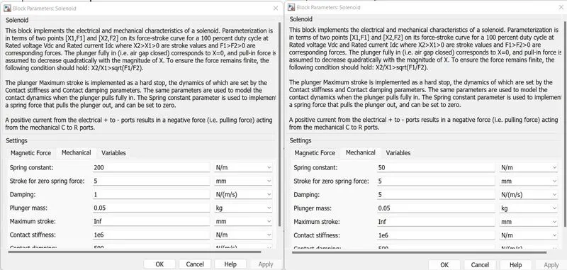
The comparison of the output plots of plunger position is shown below.
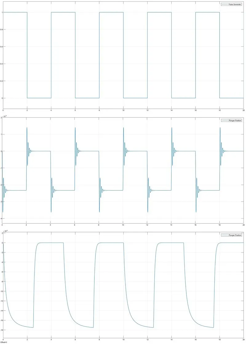
- With the decrease of the stiffness of the string and increase in the damping we can observe that the position of the plunger is opposite to the input pulse because initially when the pulse amplitude ‘1’ the input signal flows through the switch it closes the circuit and current flow through the solenoid then plunger hits the bell and it won’t come back to its normal position at earliest when the pulse amplitude reaches ‘0’due to low spring constant and increasing in damping and with a time delay of t=2sec again pulse amplitude became ‘1’, so that again the plunger hits the bell and again it repeats till the end of the simulation.
Q2.
Use a thermistor to sense the temperature of a heater & turn on or turn off the fan as per the below conditions:
Temperature source: 20 °C from 0 to 10 seconds, 27 °C from 10 to 30 seconds, 23 °C from 30 to 50 seconds
Fan conditions: ON if the temperature is above 25 °C, OFF otherwise
ANS: -
Major components used to construct the Model:
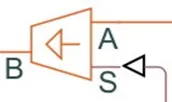
Controlled Temperature sensor: This block represents an ideal energy source in a thermal network that can maintain a controlled temperature difference regardless of the heat flow rate. The temperature difference is set by the physical signal port S. A positive temperature difference causes the temperature at port B to be greater than the temperature at port A.
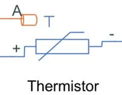
Thermistor: A thermistor is a type of resistor whose resistance is strongly dependent on temperature, more so than in standard resistors. The Thermistor block represents an NTC thermistor using the B-parameter equation. NTC thermistors are widely used as inrush current limiters, and temperature sensors, while PTC thermistors are used as self-resetting overcurrent protectors and self-regulating heating elements.
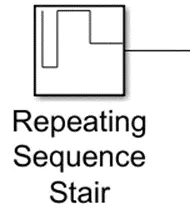
Repeating Sequence Stair: The Repeating Sequence Stair block outputs and repeats a stair sequence that you specify with the Vector of output values parameter.
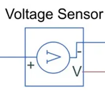
Voltage Sensor: The Voltage Sensor block represents an ideal voltage sensor, that is, a device that converts voltage measured between two points of an electrical circuit into a physical signal proportional to the voltage.
Connections + and – are electrical conserving ports through which the sensor is connected to the circuit. Connection V is a physical signal port that outputs the measurement result.
Resistor: Use the resistor class to create a resistor object that you can add to an existing circuit.
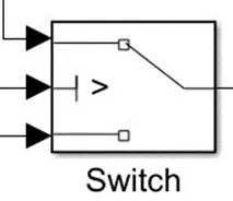
Switch: The Switch block passes through the first input or the third input signal based on the value of the second input. The first and third inputs are data inputs. The second input is a control input. Specify the condition under which the block passes the first input by using the Criteria for passing the first input and Threshold parameters.
SIMULINK MODEL:
Explanation:
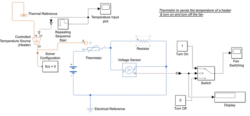
- The source port of the controlled temperature sensor is connected to the Repeating sequence stair signal input through Simulink-PS which will provide the signal as per the specified vector values.
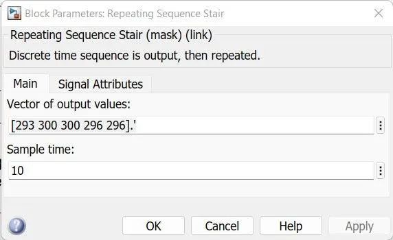
- The given temperature values were 20,27,23 in Celsius degrees, we have converted the same into 293.15,300.15,296.15 kelvin degrees accordingly. We have a condition given that at 25 Celsius degree (298.15) fan needs to be turned on and as per the given condition, the vector values of the input signal will be [293 300 300 296 296] with a time sample of 10 sec so that overall time period of 50sec.
- Port A of the temperature source given to the thermal reference that is, a point with an absolute zero temperature, with respect to which all the temperatures in the system are determined. Port B is given to Port A of thermistor block and solver configuration.
- The positive terminal of the thermistor was given to the 12v battery and the negative terminal was given to a resistor. The voltage sensor is connected across the resistor to sense and measure the voltage across the resistor. The negative port of the resistor and sensor are connected to the battery negative along with the electrical reference.
- The V port of the sensor is given to the switch through the PS-Simulink. Two constant blocks having the values of 1,0 are connected to the switch.
- In the thermistor block the reference temperature set for 293.15 kelvin = 25-celsius degree.
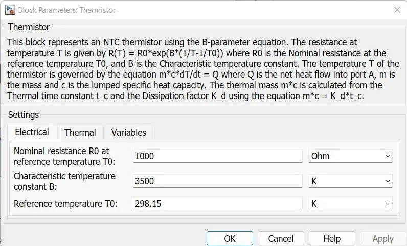
- When the temperature crosses the 298 kelvins, the rise in the temperature will increase the resistance in the resistor which changes the voltage across the resistor will sense by the voltage sensor, it will give the physical signal to switch to turn on the fan to cool the circuit.
- Scope block connected at input signal and at the output signal which will show the turn on & off of the fan according to the temperature.
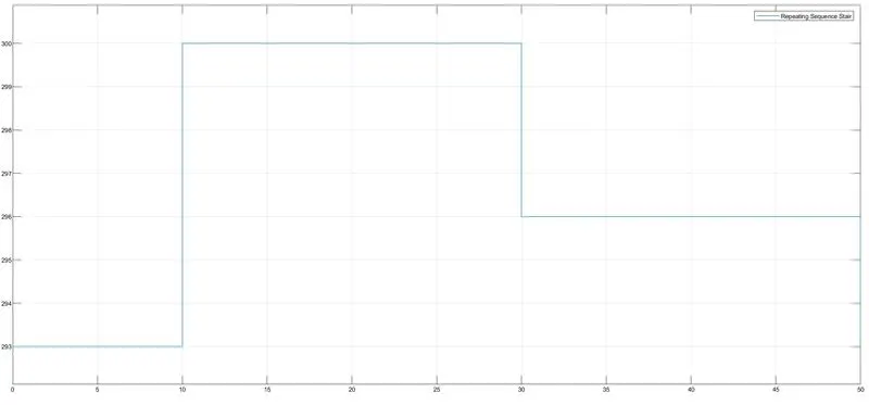
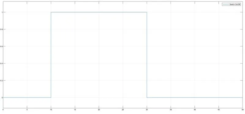
“From the above plots, we can see that when the temperature was above the 298-kelvin fan switch turned on and when the temperature dropped below the 298-kelvin fan switch gets turned off”