Week 7 Challenge
Load the vehicle parameters. Complete the vehicle model by modeling the remaining equations. Set simulation stop time to 598 sec.
The output should be the vehicle velocity.
SOL: -
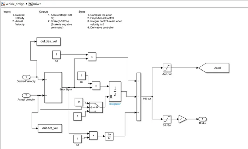
The Vehicle model by modeling the Driver block with inputs (Desired velocity and Actual velocity) and outputs (acceleration and brake) controlled by the PID controller. The Vehicle body consists of forces acting on the vehicle and the resultant vehicle velocity.
Driver block
Vehicle Body model
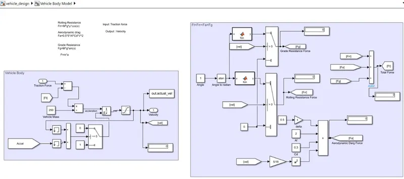
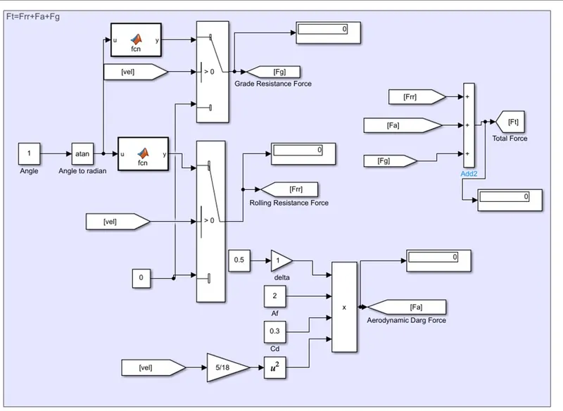
Vehicle Body
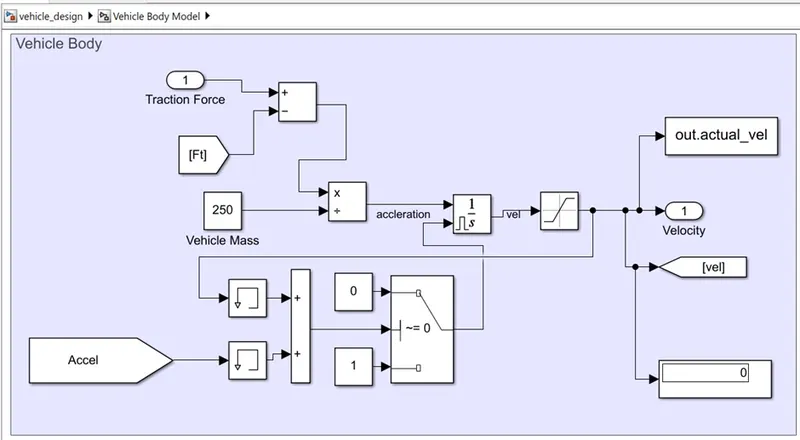
Forces acting on Vehicle
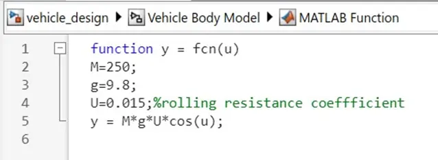
- Rolling Resistance Frr=M*g*μ*cos(α)
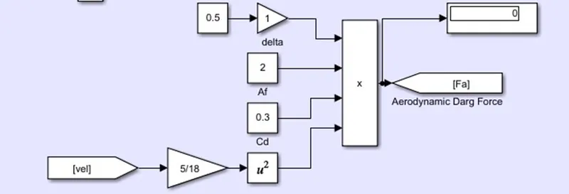
- Aerodynamic drag Fa=0.5*δ*Af*Cd*V^2
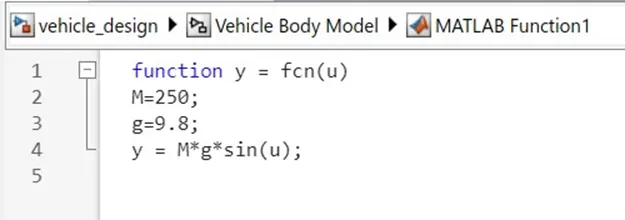
- Grade Resistance Fg=M*g*sin(α)
- Total Force Ft= Frr+Fa+Fg
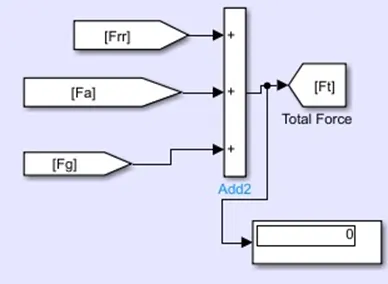
The required parameters such as vehicle mass, gravity, coefficient of rolling resistance, Frontal area, drag coefficient, and air density(delta) were assigned in the model itself as shown in the above pictures.
The tractive force developed in the vehicle was provided by using the signal builder block shown below
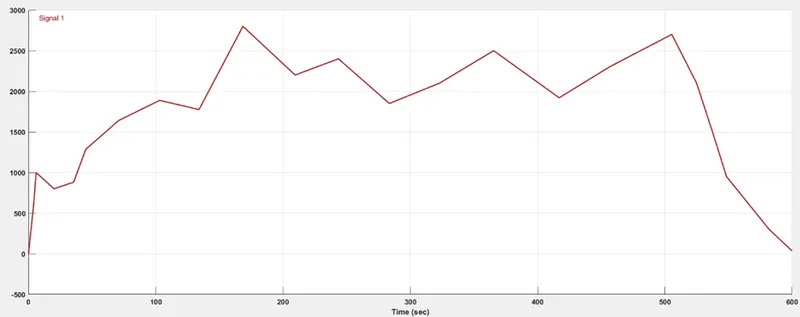
Vehicle Model
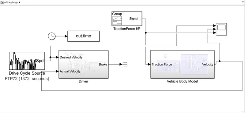
The FTP72 drive cycle is taken as the desired velocity of the system and the signal of the vehicle velocity is given to the SCOPE to visualize with the comparison of Desired velocity and tractive force.
Run the simulation for the time period of T=598 sec
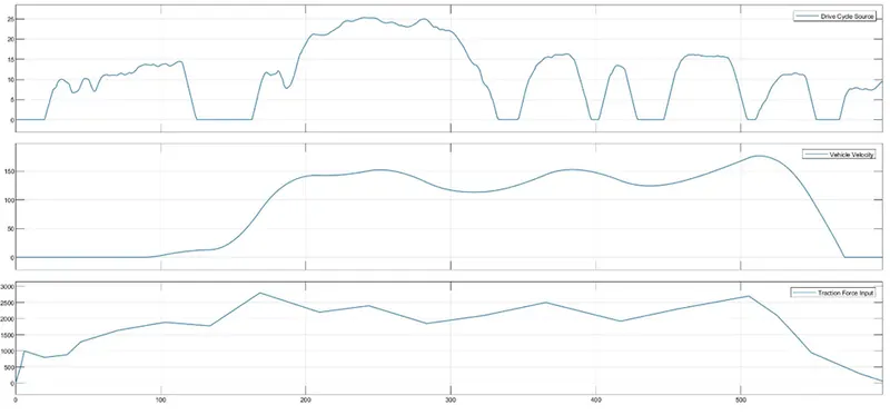
From the above plot, we can say that the vehicle is able to provide movement when the tractive force is nearly 2000N with the provided parameters of the controller and considered parameters of the vehicle.
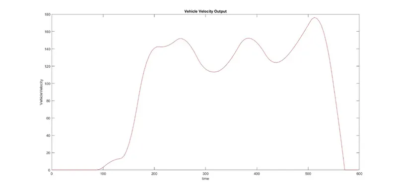
The output: vehicle velocity